
 Open Access Article
 This Open Access Article is licensed under a Creative Commons Attribution-Non Commercial 3.0 Unported Licence
A smelting–rolling strategy for ZnIn bulk phase alloy anodes†
Yizhao
Chai
a,
Xuesong
Xie
a,
Zhangxing
He
*b,
Guangyi
Guo
c,
Pinji
Wang
a,
Zhenyue
Xing
a,
Bingan
Lu
d,
Shuquan
Liang
 a,
Yan
Tang
*a and
Jiang
Zhou
*ae
a,
Yan
Tang
*a and
Jiang
Zhou
*ae
aSchool of Materials Science and Engineering, Hunan Provincial Key Laboratory of Electronic Packaging and Advanced Functional Materials, Central South University, Changsha 410083, China. E-mail: ty_csu@csu.edu.cn; zhou_jiang@csu.edu.cn
bSchool of Chemical Engineering, North China University of Science and Technology, Tangshan 063009, China. E-mail: zxhe@ncst.edu.cn
cSchool of Materials Science and Engineering, Hunan Provincial Key Laboratory of Nonferrous Materials Science and Engineering, Central South University, Changsha 410083, China
dSchool of Physics and Electronics, Hunan University, Changsha 410082, China
eCollege of Chemistry and Chemical Engineering, Jishou University, Jishou 416000, China
First published on 20th September 2022
Abstract
Reversibility and stability are considered as the key indicators for Zn metal anodes in aqueous Zn-ion batteries, yet they are severely hindered by uncontrolled Zn stripping/plating and side reactions. Herein, we fabricate a bulk phase ZnIn alloy anode containing trace indium by a typical smelting–rolling process. A uniformly dispersed bulk phase of the whole Zn anode is constructed rather than only a protective layer on the surface. The Zn deposition can be regarded as instantaneous nucleation due to the adsorption of the evenly dispersed indium, and formation of the exclusion zone for further nucleation can be prevented at the same time. Owing to the bulk phase structure of ZnIn alloy, the indium not only plays a crucial role in Zn deposition, but also improves the Zn stripping. Consequently, the as-designed ZnIn alloy anode can sustain stable Zn stripping/plating for over 2500 h at 4.4 mA cm−2 with nearly 6 times smaller voltage hysteresis than that of pure Zn. Moreover, it enables a substantially stable ZnIn//NH4V4O10 battery with 96.44% capacity retention after 1000 cycles at 5 A g−1. This method of regulating the Zn nucleation by preparing a Zn-based alloy provides a potential solution to the critical problem of Zn dendrite growth and by-product generation fundamentally.
Introduction
The ever-increasing demand for environmentally friendly energy consumption stimulates the development of new green energy storage devices.1,2 Aqueous Zn-based batteries have received considerable attention due to their abundant resource of raw materials, eco-friendliness, high theoretical capacity (820 mA h g−1 and 5854 mA h cm−3) and low Zn2+/Zn redox potential (−0.76 V vs. standard hydrogen electrode).3–5 However, they encounter intrinsic limitations for practical application including dendrite growth and undesired side reactions,6,7 which are mainly attributed to the uncontrollable Zn deposition caused by non-uniform interface electric field distribution at the anode/electrolyte interfaces,8,9 presenting a challenge to realizing high coulombic efficiency (CE) for metallic Zn anodes. To mitigate these issues, numerous efforts have been made to inhibit dendrite growth and restrain side reactions, such as the artificial solid electrolyte interphase (SEI) layer,10,11 the 3D structure of the Zn anode9,12 and electrolyte modifications.13,14 However, these studies only focus on changing the environment of the Zn anode surface to alleviate the dendrite growth and corrosion. These measures may be ineffective with the plating of Zn and severe Zn dendrite formation occurs with inhomogeneous nucleation and deposition layer formation, leading to the failure of the battery. Therefore, it is highly desirable to explore a new Zn anode to regulate the Zn nucleation, thereby fundamentally inhibiting dendrite growth and restraining side reactions simultaneously.The alloying strategy is proved to be effective in addressing these difficulties by reconstructing the anode itself. Inspired by this, Zn-based alloys have been applied as the anode of Zn-ion batteries, which can lower the Zn deposition energy barrier or provide Zn deposition channels, including ZnCu alloy,15 ZnMn alloy,16 and ZnSn alloy.17 However, only an alloy film on the surface of the substrate can be constructed rather than changing the structure and composition of the bulk metallic Zn anode when using these methods. With the deposition layer formation, inhomogeneous nucleation always takes place and causes uncontrollable dendrite growth. Moreover, large-scale production is difficult due to the complexity of the preparation process. Smelting–rolling is a typical method to prepare bulk phase alloys instead of only constructing an alloy film on the electrode surface, which is economical and suitable for large-scale production. Unlike surface modification, for this bulk phase alloy, the nucleation process of Zn on the anode at each cycle is the same as for the initial state. Moreover, the evenly distributed alloying element can be readily controlled, which is important for the uniform nucleation of the Zn anode. Among the alloying elements, indium has low resistivity and high hydrogen evolution overpotential (−0.342 V vs. SHE)11,18 and has been used as a mercury-substitute inhibitor for the Zn anode in alkaline Zn–Mn batteries to inhibit the corrosion of Zn metal.19,20 Moreover, it has been proved by calculation that indium has strong adsorption to Zn, and can be used as “seeds” to adsorb Zn ions, thereby inducing uniform deposition of Zn.
In this work, we report the preparation of a ZnIn bulk phase alloy anode containing trace indium via a typical smelting–rolling process. The content of indium is only 0.4%, hence there is almost no loss of active material in comparison with the reported Zn88Al12 alloy and Zn3Mn alloy.16,21 Moreover, the bulk phase design can reconstruct the Zn anode rather than just generating a protective film on the surface. Thus, the ingredient homogeneity of the bulk phase of ZnIn alloy is maintained during the plating and stripping of the ZnIn anode. The nucleation mechanism is regarded as instantaneous nucleation due to the adsorption of uniform indium and the fast kinetics of Zn deposition, accelerating the nucleation rate of Zn on the ZnIn alloy anode. Therefore, the initial nuclei are distributed evenly, which alleviates the effect of the electrolyte/anode interface diffusion zones. After that, the Zn nuclei grow together in the form of nanoparticles, and the surface of the anode gradually becomes smooth along with the grain growth. Meanwhile, formation of the exclusion zone for further nucleation can be prevented compared with pure Zn. As a result, the ZnIn symmetrical battery can cycle for over 2500 h at a current density of 4.4 mA cm−2 and capacity of 1.1 mA h cm−2 with a smaller polarization voltage. The outstanding electrochemical properties also enable the ZnIn//NH4V4O10 full cell to deliver 1000 cycles with 96.44% capacity retention.
Experimental
Preparation of the ZnIn alloy anode
ZnIn alloy was prepared by melting, casting and rolling processes. Firstly, 4990 g of high-purity zinc (99.99%) and 10 g of high-purity indium (99.99%) were melted and mixed well in a smelting furnace and stirred evenly. The melting temperature was 420 °C, which is close to the melting point of Zn. After that, the molten alloy was cooled to room temperature in the air, and the ZnIn alloy ingot was obtained. Then the ZnIn alloy ingot was cut into alloy plates with a thickness of 2 mm by wire cutting. After removing the oxide layer and impurities on the surface by grinding and polishing, the alloy plate was hot-rolled at a temperature of 200 °C. Ultimately, the ZnIn alloy sheet with a thickness of 200 μm was obtained and further polished for use as the anode.Fabrication of the NH4V4O10 cathode material
NH4V4O10 was synthesized by the hydrothermal method described in ref. 22. Typically, 1.170 g of NH4VO3 was dissolved in 50 mL deionized water and heated to 80 °C. Then, 1.891 g of H2C2O4·2H2O powder was added to the NH4VO3 solution and stirred until it became black-green. After that, the solution was transferred to a Teflon-lined autoclave and heated at 140 °C for 48 h. The products were collected and washed repeatedly with deionized water after the sample was cooled to room temperature naturally. The final product was dried at 60 °C for 12 h to obtain NH4V4O10.Material characterization
XRD measurements were conducted on an XRD diffractometer (Rigaku Mini Flex 600 diffractometer) using Cu Kα radiation. Morphology images were collected on a field-emission scanning electron microscope (FEI Nova Nano SEM 230, 10 kV). Notably, to avoid the effect of the separator, the electrodes characterized by SEM are cycled and plated in 2 M ZnSO4 electrolyte without separator. Electron probe microanalysis (EPMA) was performed on a JXA-8230 instrument with wavelength-dispersive X-ray spectroscopy (WDS) characterization. The optical microscope photo was obtained on a Keyence VHX-5000 instrument. The in situ optical microscope study was conducted on an LW750LJT Transflective Optical Microscope. TEM images were collected on a Tecnai G2 20 S-TWIN Transmission Electron Microscope.Electrochemical measurements
All electrochemical testing was carried out in a 2025-type coin cell configuration. For the full cells, the cathode electrodes were composed of NH4V4O10, conductive carbon black and polyvinylidene fluoride (PVDF) at a mass ratio of 7![[thin space (1/6-em)]](https://www.rsc.org/images/entities/char_2009.gif) :2:1. The pure Zn and ZnIn alloy were punched into disks (Φ = 15 mm) and served as the counter electrode. The cathode and anode electrodes were separated by glass fiber separators (Φ = 19 mm, Whatman). 2 M ZnSO4 aqueous solution was used as the typical liquid electrolyte. And for symmetric cells, the pure Zn and ZnIn alloy were punched into disks (Φ = 12 mm). Galvanostatic charge/discharge cycling measurements were carried out on a LAND multichannel battery test system (CT2001A, China) at different current densities at room temperature (25 °C). Cyclic voltammetry (CV) profiles were recorded on an electrochemical station (CHI 660E, China) at a scan rate of 0.1 mV with a voltage range of 0.4–1.4 V. The linear sweep voltammetry (LSV) curves and chronoamperometry (CA) data at different overpotentials were also recorded on it. The electrochemical impedance spectroscopy (EIS) data of the electrodes were acquired at room temperature using a ZAHNER-IM6ex electrochemical workstation (ZAHNER Co., Germany) in the frequency range of 100 kHz to 0.01 Hz on symmetric cells.
:2:1. The pure Zn and ZnIn alloy were punched into disks (Φ = 15 mm) and served as the counter electrode. The cathode and anode electrodes were separated by glass fiber separators (Φ = 19 mm, Whatman). 2 M ZnSO4 aqueous solution was used as the typical liquid electrolyte. And for symmetric cells, the pure Zn and ZnIn alloy were punched into disks (Φ = 12 mm). Galvanostatic charge/discharge cycling measurements were carried out on a LAND multichannel battery test system (CT2001A, China) at different current densities at room temperature (25 °C). Cyclic voltammetry (CV) profiles were recorded on an electrochemical station (CHI 660E, China) at a scan rate of 0.1 mV with a voltage range of 0.4–1.4 V. The linear sweep voltammetry (LSV) curves and chronoamperometry (CA) data at different overpotentials were also recorded on it. The electrochemical impedance spectroscopy (EIS) data of the electrodes were acquired at room temperature using a ZAHNER-IM6ex electrochemical workstation (ZAHNER Co., Germany) in the frequency range of 100 kHz to 0.01 Hz on symmetric cells.
Computational methods
We employed the Vienna Ab initio Package (VASP)23,24 to perform all the density functional theory (DFT) calculations within the generalized gradient approximation (GGA) using the PBE formulation.25 We chose the projector augmented wave (PAW) potentials26,27 to describe the ionic cores and take valence electrons into account using a plane-wave basis set with a kinetic energy cutoff of 400 eV. Partial occupancies of the Kohn–Sham orbitals were allowed using the Gaussian smearing method and a width of 0.05 eV. The electronic energy was considered self-consistent when the energy change is smaller than 10−4 eV. Geometry optimization was considered convergent when the force change was smaller than 0.04 eV Å−1. Grimme's DFT-D3 methodology28 was used to describe the dispersion interactions. The Brillouin zone integral used the surfaces structures of 3 × 3 × 1 Monkhorst–Pack K point sampling. Finally, the adsorption energies (Eads) were calculated as Eads = Ead/sub − Ead − Esub, where Ead/sub, Ead and Esub were the optimized adsorbate/substrate system, the adsorbate in the structure and the clean substrate respectively.Finite element method simulations
The modeling of Zn electrodeposition was performed by using COMSOL Multiphysics 5.6 based on the finite element method. This simulation includes migration and diffusion under the interaction exported by the electric field. The electrochemical deposition process of Zn metal was simulated using the “secondary current distribution” model interface. The “Deformable Geometry” interface is coupled to the “secondary current distribution” interface to track deformability on the electrode surface. The Butler–Volmer equation was employed to introduce the reaction of the electrode surface. The flux of each ion in the electrolyte is calculated by the Nernst–Planck equation. The initial concentration of Zn2+ was set to 2.0 mol L−1. The average current density of the electrode is 5 mA cm−2 and the deposition time is 60 s.Results and discussion
The ZnIn alloy ingot was synthesized by melting the pure zinc and pure indium together and casting an ingot from the melt at 420 °C, then the ingot was hot-rolled at 200 °C after wire cutting to create ZnIn alloy sheets about 200 μm in thickness. The schematic diagram visualizes the main strategy to fabricate the ZnIn alloy (Fig. 1a). Firstly, the morphologies of the ZnIn alloy were characterized using an optical microscope (OM). A structure similar to martensite can be observed due to the incorporation of foreign elements of indium (Fig. S1†). The martensite has a high dislocation density, leading to a higher adsorption energy to Zn atoms29,30 and facilitating the rapid deposition of Zn. The X-ray photoelectron spectroscopy (XPS) of ZnIn alloy displays a slight shift, which is mainly due to the formation of Zn–In polar bonds at the surface of ZnIn alloy and the enhancement of the binding energy (Fig. 1b).31,32 Meanwhile, there is no obvious indium peak in the indium fine spectrum due to the negligible addition of indium (Fig. S2†). The XRD patterns of ZnIn alloy are almost the same as those of the pure Zn (Fig. S3†), indicating the addition of indium does not change the phase of Zn metal.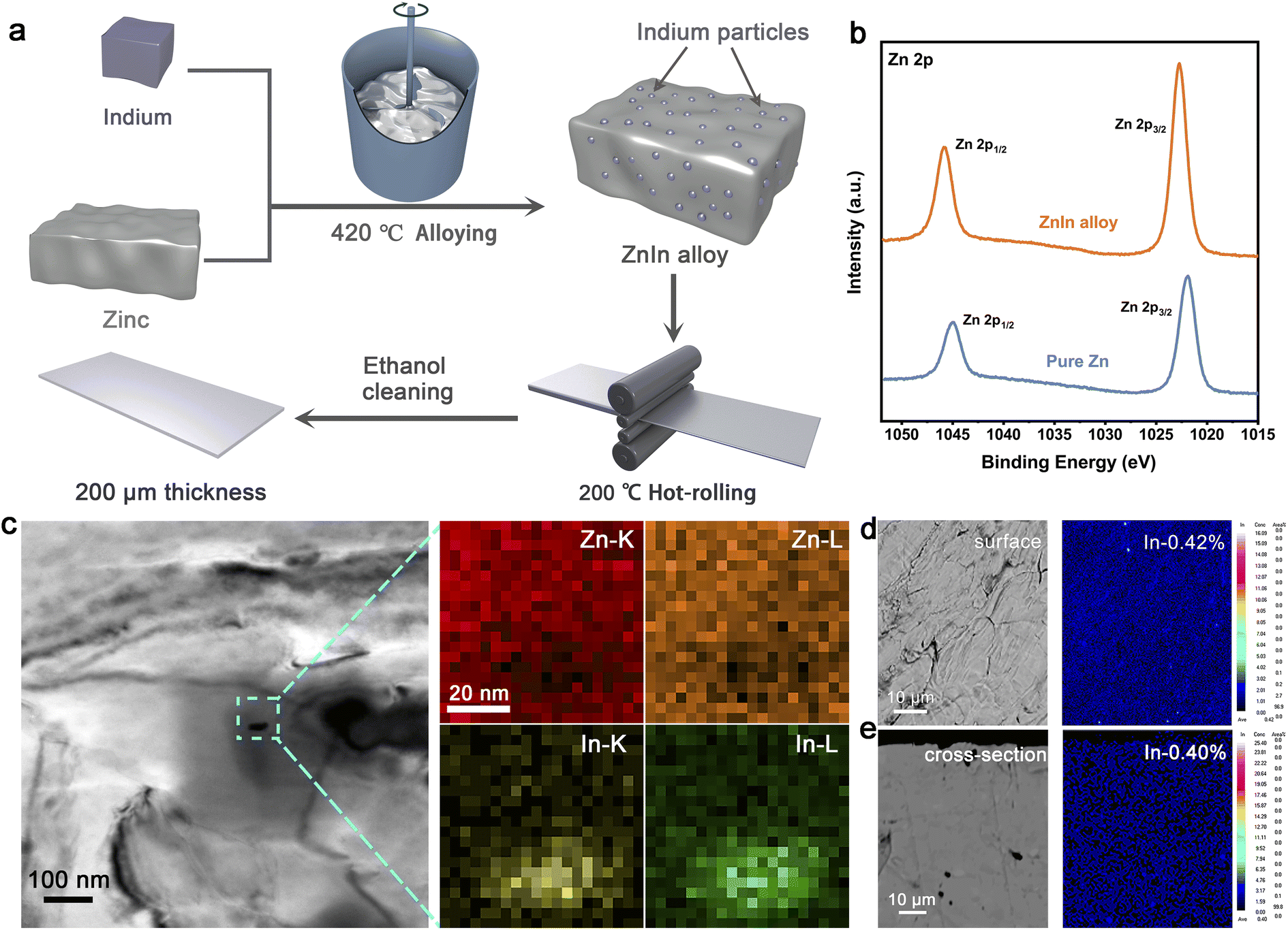 | ||
| Fig. 1 Fabrication and characterization of ZnIn alloy. (a) Schematic of the fabrication process of ZnIn alloy. (b) High-resolution XPS spectra of Zn 2p for ZnIn alloy and pure Zn. (c) Bright-field image of ZnIn alloy with the EDS mapping images of the selected area for Zn and indium elements. (d and e) The surface and cross-section morphologies of ZnIn alloy with their corresponding EPMA mappings. | ||
Furthermore, a typical bright-field transmission electron microscope (TEM) image of the ZnIn alloy is shown in Fig. 1c. It is found that a very small size (about 30 nm) dispersoid is distributed inside the Zn metal grain. Meanwhile, the EDS mapping displays the electron excitation intensities of the K and L layers of Zn and In elements, indicating that the dispersoid is indium. The distribution of indium element on the alloy matrix surface is examined by electron probe microanalysis in wavelength-dispersive X-ray mode (EPMA-WDS) (Fig. 1d). No obvious elemental enrichment can be seen, confirming the homogeneous dispersion of indium that can also be revealed in the cross-section scan (Fig. 1e). The content of indium in the surface and cross-section is approximately the same, suggesting that indium is evenly distributed throughout the bulk of the alloy. In order to explore whether the ZnIn alloy can be applied as the anode for the aqueous Zn-ion battery, the cyclic voltammetry (CV) curves of both pure Zn//stainless steel (pure Zn//SS) and ZnIn alloy//SS half cells were tested (Fig. S4†). There is no other peak but a pair of redox peaks and their positions are the same in both cells, further demonstrating that the addition of trace indium renders unchanged electrochemical reaction of Zn stripping/plating. In addition, the current density of the redox peak in ZnIn alloy//SS is higher than that of pure Zn, indicating that ZnIn alloy has faster reaction kinetics. These results demonstrated the existence of indium with homogeneous distribution in the ZnIn bulk phase alloy.
The deposition process of Zn is the key factor that affects the electrochemical performance of the anode. To explore the deposition behavior of Zn on the ZnIn alloy surface, chronoamperometry (CA) measurements are carried out for both ZnIn//ZnIn and Zn//Zn symmetric cells to evaluate the feature of the Zn plating process (Fig. S5†). The Scharifker and Hills model is employed to illustrate the nucleation and growth process of three-dimensional multiple nucleates with diffusion-controlled growth. According to the Scharifker and Hills model, there are two limiting cases of nuclear forms, which are instantaneous nucleation and progressive nucleation. Instantaneous nucleation means that nuclei arise in all possible nucleation sites in the initial potential step at the same time, and then grow together. In contrast, progressive nucleation refers to the slow nucleation on the small number of active sites. In the subsequent growth process, the number of nucleation sites will be decreased gradually because of the growing nuclei and exclusion zones for nucleation.33 The instantaneous and progressive nucleation expressions are displayed as follows:
Instantaneous nucleation:
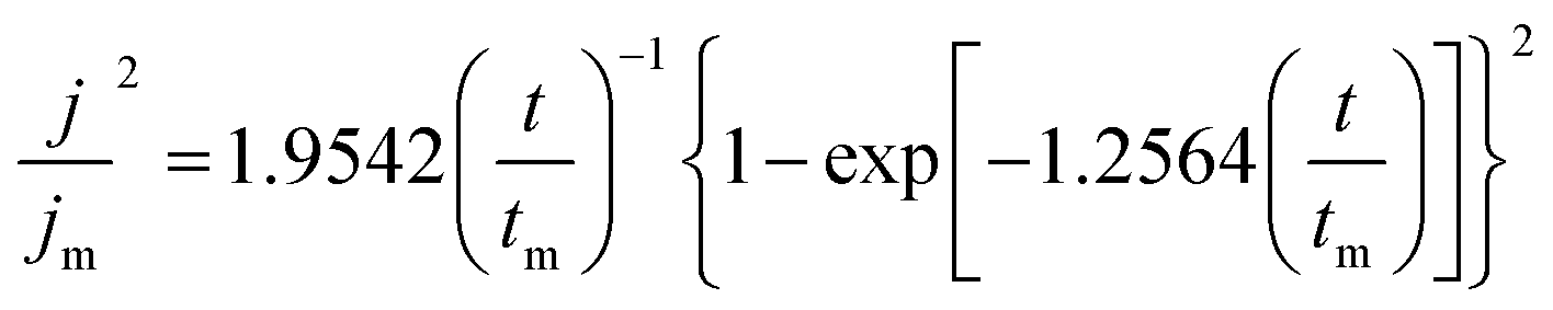
Progressive nucleation:
The transient current expressions tested in CA measurement at different potentials are nondimensionalized, which are in agreement with the instantaneous nucleation shown in Fig. 2a, reflecting that Zn deposits rapidly on the surface of ZnIn alloy at all of the nucleation sites. This nucleation mode suggests the faster nucleation rate of Zn endowed by indium in the ZnIn alloy.34 The voltage profiles of Zn deposition onto ZnIn alloy and pure Zn were also monitored to confirm the enhanced kinetics of ZnIn alloy. As shown in Fig. 2b, ZnIn alloy exhibits only 15.8 mV nucleation overpotential at a current density of 0.5 mA cm−2, which is lower than that of pure Zn (17.7 mV), illustrating that ZnIn alloy affords a lower nucleation energy barrier and has a better zincophilicity.35,36 The same trend is also confirmed at different current densities of 1.0, 2.0, and 5.0 mA cm−2 (Fig. S6†).
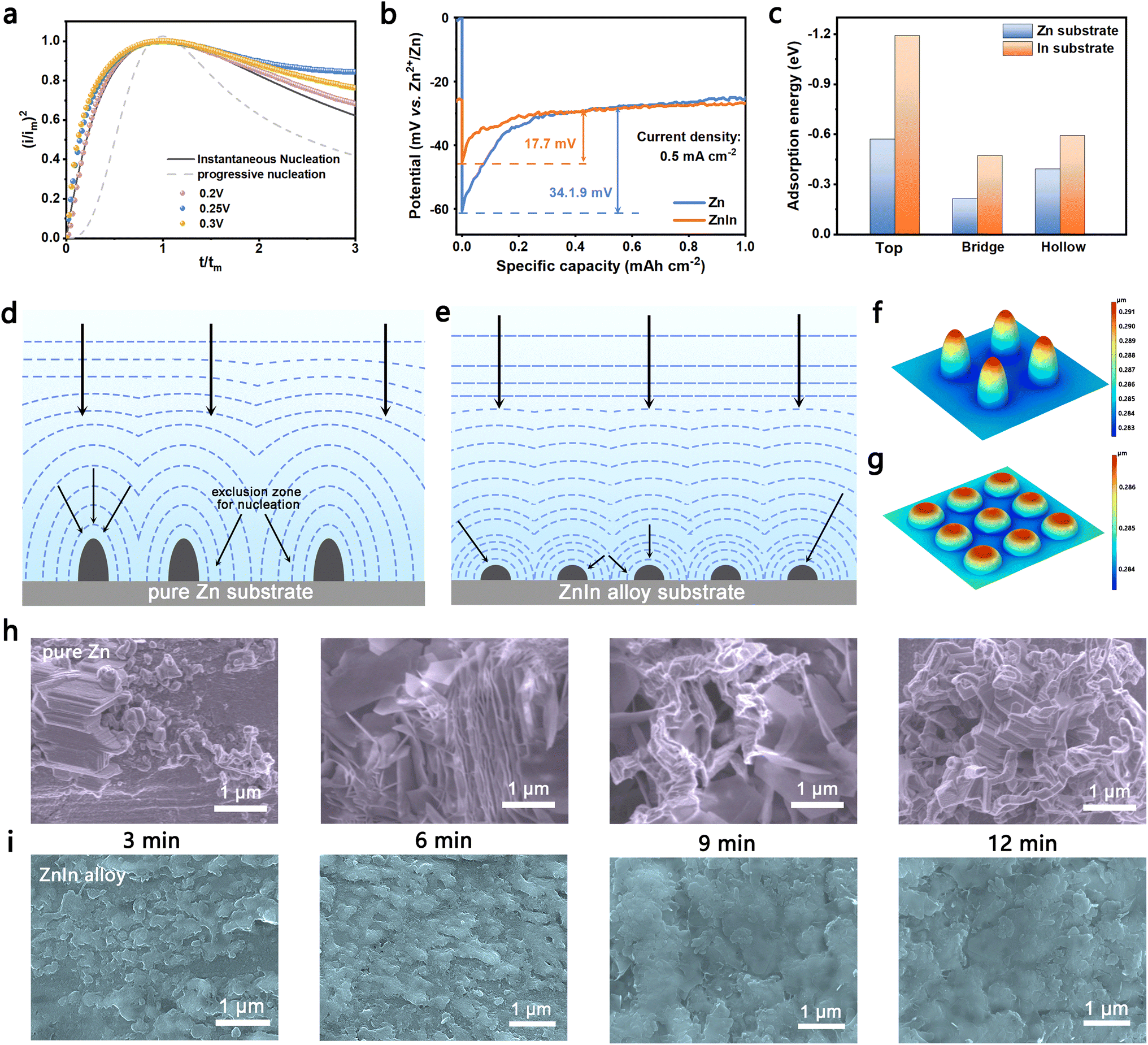 | ||
| Fig. 2 Zn nucleation and growth process. (a) Comparison of the theoretical dimensionless plots for instantaneous nucleation and the experimental nucleation process for ZnIn alloy at different overpotentials. (b) Nucleation overpotential of Zn on pure Zn and ZnIn alloy at 0.5 mA cm−2. (c) Adsorption energies of the Zn atom on Zn and indium substrates. (d and e) Schematic diagram of nuclei growth on pure Zn and ZnIn alloy. (f and g) Thickness changes after 60 s of Zn plating on the pure Zn and ZnIn alloy surface by the finite element method. (h and i) The morphologies of Zn depositing on pure Zn and ZnIn alloy for 3 min, 6 min, 9 min and 12 min at a current density of 5 mA cm−2. | ||
Theoretical calculation based on density functional theory (DFT) is performed to investigate the effect of indium alloying additive during Zn deposition (Fig. S7†). Fig. 2c shows the adsorption energies of Zn atom on different adsorption sites on the indium substrate are −1.19 (Top), −0.47 (Hollow), and −0.59 (Bridge) eV, respectively. They are higher than those on the Zn substrate (−0.57, −0.22, and −0.39 eV), suggesting the strong propensity of zincophilicity for ZnIn alloy.37 The finite element method is also used to verify that indium in ZnIn alloy is more electrochemically active for the deposition of Zn. As shown in Fig. S8,† the bottom circles are set as indium and the others are set as Zn. Compared to other areas, the electrolyte potential near the indium elements is lower, Zn2+ from the electrolyte tends to migrate to indium element. Meanwhile, due to the good affinity to Zn of the uniformly distributed indium, the nuclei of Zn depositing on ZnIn alloy are homogeneous. As a result, the ZnIn alloy anode can not only exhibit excellent deposition kinetics, but also absorb Zn on the uniform indium element fast, thus showing the nucleation mode of instantaneous nucleation.
Fig. 2d and e show the scheme of the growth process for the nucleus after initial nucleation. The dotted lines represent the diffusion zone of the surrounding area. The Zn nuclei depositing on pure Zn are randomly distributed. While the nuclei grow, as the diffusion zones grow and overlap, replacement of the material on the electrode surface close to the nucleus is hindered. As a result, there is an exclusion zone for further nucleation around an already nucleated center due to local deformation of the electric field around the growing nuclei, which can inhibit Zn depositing in these areas.38 Finally, the nuclei give rise to preferential deposition of Zn at tip-spots. In contrast, Zn nucleates on the indium seeds and then grows into Zn particles. These Zn particles are distributed uniformly so that the ZnIn alloy can be covered with uniform and smooth Zn deposits. Therefore, the deposition of Zn on ZnIn alloy has less effect on the diffusion zone of the anode/electrolyte interface than deposition on pure Zn and suppresses the “tip effect” by regulating the local deformation of the electric field. The growth process of nuclei can also be confirmed by the finite element method (Fig. 2f and g). After deposition for 60 s at a current density of 5 mA cm−2, the maximum value of the deposition thickness on pure Zn occurs around the tips of the nuclei (0.291 μm), which is thicker than that of ZnIn alloy.
To confirm the growth process for deposition as mentioned above, the morphologies after Zn plating on ZnIn alloy and pure Zn were illustrated by SEM characterization. We observed the status quo of its surface after deposition 3, 6, 9 and 12 min at the current density of 5 mA cm−2, respectively (Fig. 2h). The scattered large Zn deposits are observed during the initial nucleation of pure Zn. As the deposition progresses, these deposits finally grow into Zn dendrites. In contrast, the morphology of the initial nucleation on the surface of the ZnIn alloy anode indicates the even distribution of Zn nuclei (Fig. 2i). As Zn deposition proceeds, the trenches between the initial nuclei filled up, compared to the protruding areas in the early stage. Thus, the separate Zn nuclei aggregate together instead of growing on the top. Finally, the connected nuclei develop into a dense layer covering the entire surface of the anode. The same deposition trend is also reflected at a current density of 1 mA cm−2 (Fig. S9†). In order to study the morphology of the bulk phase alloy during Zn stripping, the electrode with different stripping times at 1 mA cm−2 (Fig. S10†) was characterized. The ZnIn alloy anode has a relatively flat surface and no obvious preferential stripping site. Reciprocally, the pure Zn anode has more uneven stripping holes. And there are large Zn dendrites on these holes, suggesting that the addition of trace indium can make the plating and stripping of Zn more uniform. Meanwhile, the in situ OM technology studies clearly show the serious dendrite growth and hydrogen evolution reaction of the pure Zn anode. In comparison, the ZnIn alloy anode retains a smooth surface without dendrite formation and discernible hydrogen evolution (Fig. S11†).
During the electrochemical cycles, the performance of the anode is a combination of plating and stripping. Therefore, it is critical to further study the morphology of the anode after cycling. The schematic diagram of the plating and cycling for the pure Zn anode is shown in Fig. 3a. For Zn depositing on the pure Zn anode, it prefers to migrate to the defects such as scratches, microcracks and dents because of the higher activity of these defects.39 Therefore, the nucleation on pure Zn is random and dispersed. The random nuclei give rise to the “tip effect” that triggers the preferential deposition of Zn, while no new nuclei appear because of the existence of an exclusion zone for nucleation. After cycling, the surface around the random Zn dendrite forms micro-voids, and these voids gradually become larger (Fig. S12†). Then, the Zn clusters on the cavities begin to fall off and become dead Zn, leading to the risk of short-circuit and capacity loss40 (Fig. S13†). The detailed SEM images of pure Zn after cycling are shown in Fig. 3b. The surface of the pure Zn anode is covered with random Zn flakes after 5 cycles. With the increase of cycle number, the micro-void appears, and many random Zn flakes exist around the void. When the cycle number increases to 100, dendrites form from stacks of deposited Zn sheets on the anode surface. The directional deposition as Zn flakes may cause more rapid penetration and an internal short circuit.41
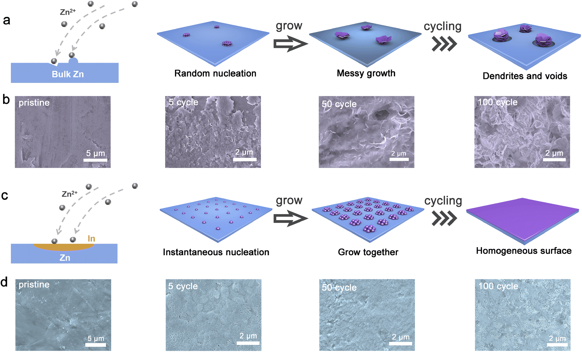 | ||
| Fig. 3 Plating and cycling process for pure Zn and ZnIn alloy. (a) Schematic diagram of nucleation, growth and cycling for the pure Zn electrode. (b) Morphologies of the pure Zn surface before cycling and after the 5th, 50th and 100th cycles. (c) Schematic diagram of nucleation, growth and cycling for the ZnIn alloy electrode. (d) Morphologies of the ZnIn alloy surface before cycling and after the 5th, 50th and 100th cycles. | ||
Conversely, the initial nucleation process is fast so that the nuclei emerge quickly on the whole surface termed instantaneous nucleation for Zn depositing on ZnIn alloy (Fig. 3c). After the initial nucleation, the nuclei grow at the same time and then connect together, tending towards a gradual smooth layer covering the ZnIn alloy surface. It still remains flat after 5, 50, and 100 cycles (Fig. S12†). Meanwhile, the XRD patterns of the cycled ZnIn alloy present nearly no change, suggesting the high reversibility and excellent interface stability (Fig. S14†). The microstructure of the anode after cycling is also examined. Zn deposits homogeneously on the surface of the anode substrate without dendrite formation and maintains a uniform and flat morphology at the following cycles (Fig. 3d). The atomic force microscope (AFM) tests exhibit an altitude intercept between the pure Zn anode (114.70 nm) and ZnIn alloy anode (84.14 nm) after 100 cycles (Fig. S15†). Moreover, the ZnIn alloy surface has obvious small granular deposition morphology. In addition, many uniformly distributed sedimentary particles are found on the ZnIn alloy surface, which may be the grown nuclei on indium sites. To further demonstrate whether the principle of deposition after cycling is the same as that before cycling, a more detailed morphology of the ZnIn alloy anode after cycles are shown in Fig. S16.† The small particles are found in each cycle, suggesting the high reversibility of the ZnIn alloy anode. To analyze the distribution of elements on the anode surface after the cycle, the distribution of indium element is also studied by EMPA (Fig. S17†). Indium element is uniformly distributed as well and the content is the same as the ZnIn alloy before the cycle, suggesting that indium element does not participate in the reaction during Zn stripping/plating. Meanwhile, there is no S element detected on the surface, demonstrating the inhibition of by-product formation for ZnIn alloy while cycling. Therefore, ZnIn alloy can manipulate the nucleation of Zn to instantaneous nucleation, and then dominate the growth of Zn nuclei to form a dense deposition layer.
To confirm the consequence of the observed reversibility of ZnIn alloy, we evaluated the stripping/plating efficiency of the Zn on pure Zn and ZnIn alloy. The coulombic efficiency (CE) measurements were carried out at a current density of 4.4 mA cm−2 with a capacity of 1.1 mA h cm−2 (vs. Cu electrode). The ZnIn//Cu cell presents a plating/stripping voltage gap of 65 mV, which is much lower than that of the Zn//Cu cell for 154 mV (Fig. 4a and b), suggesting the lower energy barrier for the nucleation/dissolution in the phase transition between Zn2+ and Zn metal.42 The corresponding CE for long-time performance is shown in Fig. 4c. The ZnIn//Cu cell exhibits a remarkably high average CE of 99.5% over 600 cycles compared with that of the pure Zn//Cu cell (only 280 cycles with an average CE of 87%), which demonstrates the severe side reactions occurring along with the Zn stripping/plating for the pure Zn anode. To further explore the hydrogen evolution resistance of the ZnIn alloy anode, the linear sweep voltammetry (LSV) curves in 1 M Na2SO4 electrolyte are displayed in Fig. S18,† exhibiting a lower onset potential for the hydrogen evolution reaction on the ZnIn alloy (−1.75 V vs. Ag/AgCl) than that on the pure Zn (−1.62 V vs. Ag/AgCl). Nyquist plots of symmetric cells are also recorded to probe the interfacial side reactions from the pristine anode to the 200th cycle at 2 mA cm−2 and 0.5 mA h cm−2 (Fig. 4d and e). The RCT of the ZnIn alloy symmetric cell decreases after the initial cycle, due to the interface activation of ZnIn alloy. It maintains a consistent value of around 15 Ω during the 10th to 200th cycle process and retains low polarization.43 In contrast, the RCT of the pure Zn symmetric cell possesses a much larger change from 400 Ω to nearly 8000 Ω. This can be attributed to the incompact by-product and the uncontrollable dendrites.44
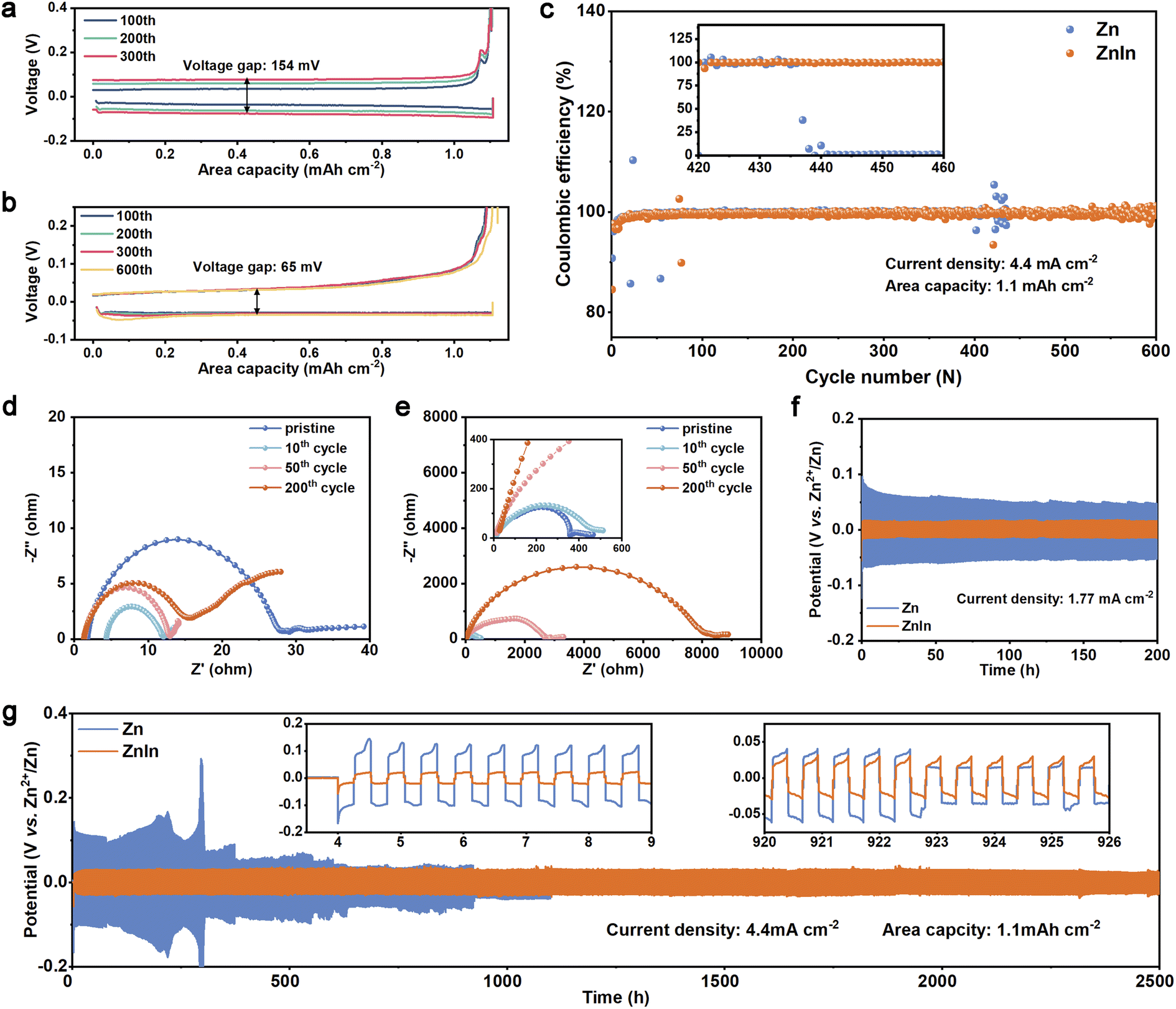 | ||
| Fig. 4 Zn plating and stripping performance. (a and b) Charge–discharge voltage gap of pure Zn and ZnIn alloy with different cycles at a current density of 4.4 mA cm−2 (vs. the Cu electrode). (c) The corresponding CE for long-time performance. (d and e) Nyquist plots of the ZnIn//ZnIn cell and Zn//Zn cell after different cycles at 2 mA cm−2 and 0.5 mA h cm−2. (f) Galvanostatic cycling performances of the ZnIn alloy and pure Zn symmetrical cells at a current density of 1.77 mA cm−2 and 0.44 mA h cm−2. (g) Long-term galvanostatic cycling performance of ZnIn alloy and pure Zn symmetrical cells at a current density of 4.4 mA cm−2 and 1.1 mA h cm−2. | ||
To further evaluate the stability of the ZnIn alloy anode, the galvanostatic cycling tests of symmetric cells are carried out at different current densities. Fig. 4f shows that the ZnIn symmetric cell has a much lower polarization (17 mV) in the first 200 cycles, compared with that of the pure Zn symmetric cell (50 mV) at a current density of 1.77 mA cm−2 with 15 min for each cycle. Meanwhile, the pure Zn symmetric cell has a large fluctuation and the overpotential decreases gradually. It is deduced that dendrite formation and the voids on the surface of the electrode cause the increase of surface area, accordingly reducing the current density and overpotential. The high current density of 4.4 mA cm−2 with a capacity of 1.1 mA h cm−2 is also measured to evaluate the long-duration cycle performance of ZnIn alloy. As shown in Fig. 4g, the ZnIn symmetric cell can maintain 5000 cycling plating/stripping processes with a lower polarization of 30 mV, while pure Zn suffers from voltage spikes (300 mV) and large fluctuation at 300 h and then recover, suggesting fast Zn-dendrite growth, dead Zn generation, and micro-shorting.45 After that, it cycles for 900 h and then shorts, only one-third of the ZnIn symmetric cell. Therefore, the ZnIn alloy anode not only displays high reversible capability by avoiding the side reaction, but also possesses higher stability compared to pure Zn.
Due to the uniform Zn deposition and high reversibility of the ZnIn alloy anode, the electrochemical properties of the ZnIn alloy and pure Zn are verified by full cells in an aqueous electrolyte (2 M ZnSO4) with NH4V4O10 as the cathode. Fig. 5a records the representative CV curve in the first 3 cycles. Compared to the Zn//NH4V4O10 cell, ZnIn//NH4V4O10 has higher capacity retention in the first 3 cycles.46 In addition, self-discharge performance is evaluated by monitoring the open-circuit voltage decay of fully charged full batteries and subsequently discharging after 10 h of storage (Fig. 5b). 88.4% of the original capacity is retained in the cell using the ZnIn anode while using pure Zn as an anode only exceeded 83.7%. The capacity retention of the ZnIn//NH4V4O10 cell for discharging after 30 h and 60 h of storage also exhibits better performance than that of the Zn//NH4V4O10 cell (Fig. S20†). The excellent performance of the ZnIn alloy anode can be ascribed to its low charge-transfer resistance promoting ion diffusion kinetics (Fig. 5c). The RCT of the ZnIn//NH4V4O10 cell of about 66 Ω is lower than that of the Zn//NH4V4O10 cell of about 366 Ω (inset of Fig. 5c). The ZnIn//NH4V4O10 cell at a low current density of 1 A g−1 shows higher stability than that of the Zn//NH4V4O10 cell within 500 cycles (Fig. 5f). The fast-deteriorating electrochemical performance in cells with the pure Zn anode is most likely due to the loss of Zn metal through “dead Zn” formation during cycling, as can be inferred from the increase of polarization of the cell after cycles (Fig. 5d). On the other hand, the overpotential of ZnIn//NH4V4O10 cells remained unchanged after 500 cycles, confirming the effectiveness of the indium element in preventing the irreversible reactions47 (Fig. 5e). Moreover, the ZnIn//NH4V4O10 cell outperforms the Zn//NH4V4O10 cell at various charge/discharge rates (Fig. 5g). Finally, the comparison of pure Zn//NH4V4O10 and ZnIn//NH4V4O10 cells for long-term cycling performance was further conducted at a current density of 5 A g−1 (Fig. 5h). The ZnIn//NH4V4O10 cell can provide a better capacity retention after 1000 cycles. Consequently, the full cell using the ZnIn alloy anode remarkably outperforms pure Zn in terms of capacity fading.
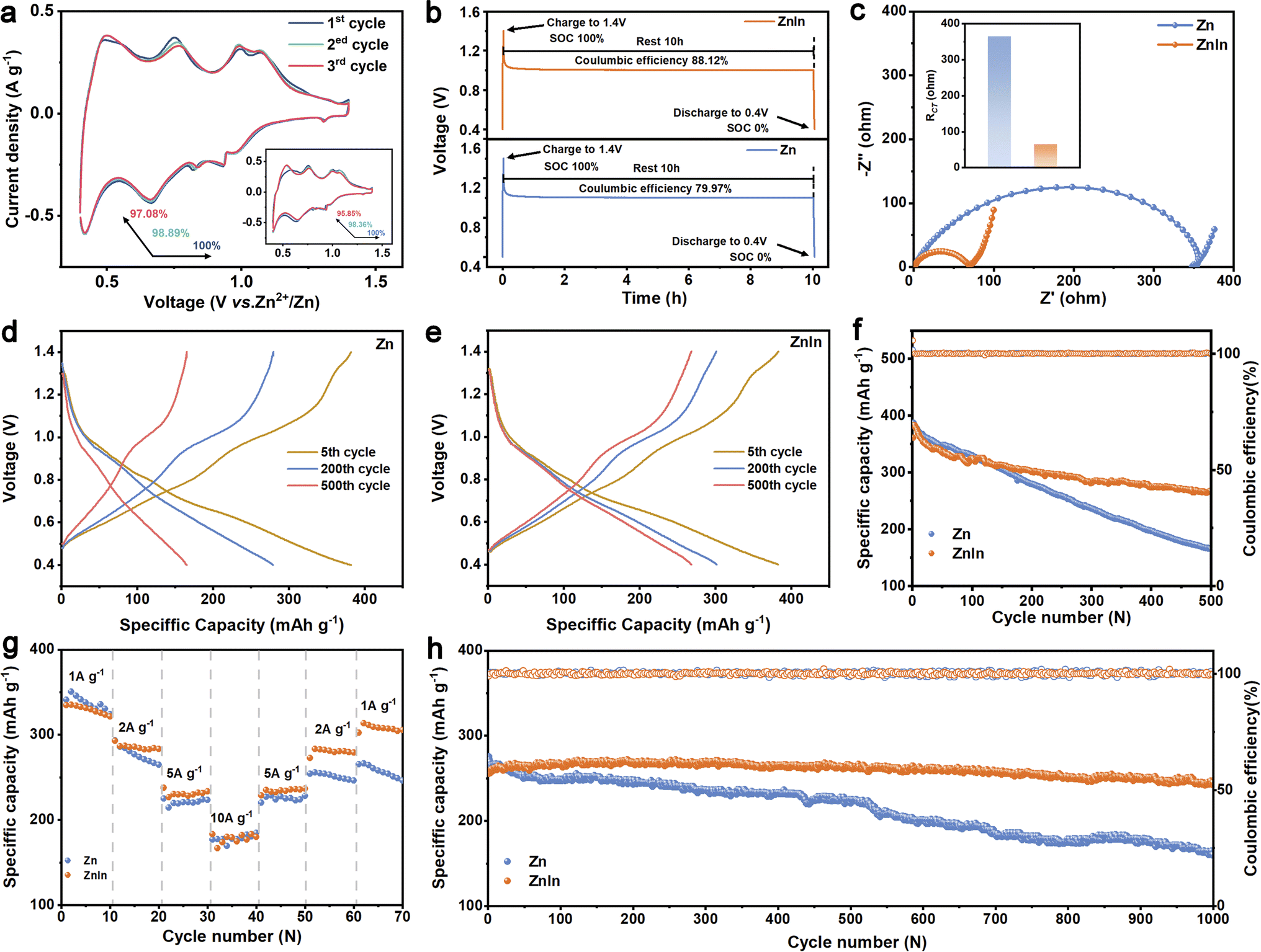 | ||
| Fig. 5 Full cell performance of pure Zn and ZnIn alloy. (a) CV curves for the first 3 cycles of ZnIn//NH4V4O10 and Zn//NH4V4O10 cells. (b) Open-circuit voltage decay of ZnIn and Zn full cells after rest 10 h. (c) Nyquist plot of Zn//NH4V4O10 and ZnIn//NH4V4O10 cells and the corresponding RCT values (inset). (d and e) Typical voltage profiles of Zn//NH4V4O10 and ZnIn//NH4V4O10 cells after the 5th, 200th and 500th cycles at a charge/discharge current density of 1 A g−1. (f) The corresponding cycling performance. (g) Rate capability of Zn//NH4V4O10 and ZnIn//NH4V4O10 cells. (h) Long-term cycling performance of ZnIn//NH4V4O10 and Zn//NH4V4O10 cells at 5 A g−1. | ||
Conclusions
In summary, a ZnIn alloy anode with a well-distributed trace indium element is prepared by a typical smelting–rolling method. Because of the higher adsorption energy to the Zn atom on the indium substrate and the lower nucleation overpotential, the Zn nucleation process will be regarded as instantaneous nucleation. In such a scenario, the effect of the electrolyte/anode interface diffusion zones during deposition can be significantly alleviated and Zn can be deposited uniformly on the ZnIn alloy anode. The dense nuclei may regulate the local deformation of the electric field to suppress Zn deposition on the top of the nuclei. By virtue of this nucleation mode, the ZnIn alloy anode will restrain dendrite growth and reduce side reactions during depositing and cycling. As a result, the ZnIn alloy anode exhibits a high CE of 99.5% at a current density of 4.4 mA cm−2 and a capacity of 1.1 mA h cm−2 for more than 600 cycles. In addition, ZnIn symmetric cells exhibit superior Zn stripping and plating performance for over 2500 h at 4.4 mA cm−2 and 1.1 mA h cm−2. Owing to the high stability and reversibility of ZnIn alloy, the ZnIn//NH4V4O10 cell also shows higher capacity retention than that of the Zn//NH4V4O10 cell. It is anticipated that the current strategy of regulating nucleation by preparing Zn alloy, thereby fundamentally solving the problems of dendrite growth and by-product generation, can pave an effective avenue for the highly reversible metal anode.Data availability
The data that support the findings of this study are available from the corresponding author upon reasonable request.Author contributions
J. Z., Z. H., and Y. T. conceived and supervised the research. Y. C. and X. X. performed the experiment and analyzed the experimental data. G. G. helped with TEM characterization. P. W. and Z. X. helped with the electrochemical data analysis. All authors read and commented on the manuscript.Conflicts of interest
There are no conflicts to declare.Acknowledgements
This work was supported by the National Natural Science Foundation of China (Grant No. 52172263 and 51972346), the Hunan Natural Science Fund for Distinguished Young Scholars (2021JJ10064), the Program of Youth Talent Support for Hunan Province (2020RC3011), and the Innovation-Driven Project of Central South University (No. 2020CX024). We are also grateful for resources from the High-Performance Computing Center of Central South University.References
- Z. Liu, L. Qin, B. Lu, X. Wu, S. Liang and J. Zhou, ChemSusChem, 2022, 15, e202200348 CAS.
- P. Ruan, X. Xu, D. Zheng, X. Chen, X. Yin, S. Liang, X. Wu, W. Shi, X. Cao and J. Zhou, ChemSusChem, 2022, 15, e202201118 CrossRef CAS PubMed.
- T. Li, D. Fang, J. Zhang, M. Pam, Z. Leong, J. Yu, X. Li, D. Yan and H. Yang, J. Mater. Chem. A, 2021, 9, 6013–6028 RSC.
- X. Li, Z. Chen, Y. Yang, S. Liang, B. Lu and J. Zhou, Inorg. Chem. Front., 2022, 9, 3986–3998 RSC.
- Z. Liu, Y. Yang, S. Liang, B. Lu and J. Zhou, Small Struct., 2021, 2, 2100119 CrossRef CAS.
- P. Wang, X. Xie, Z. Xing, X. Chen, G. Fang, B. Lu, J. Zhou, S. Liang and H. J. Fan, Adv. Energy Mater., 2021, 11, 2101158 CrossRef CAS.
- P. Ruan, S. Liang, B. Lu, H. J. Fan and J. Zhou, Angew. Chem., Int. Ed., 2022, 61, e202200598 CrossRef CAS PubMed.
- T. Li, Y. Lim, X. Li, S. Luo, C. Lin, D. Fang, S. Xia, Y. Wang and H. Yang, Adv. Energy Mater., 2022, 12, 2103231 CrossRef CAS.
- Q. Zhang, J. Luan, Y. Tang, X. Ji and H. Wang, Angew. Chem., Int. Ed., 2020, 59, 13180–13191 CrossRef CAS PubMed.
- L. Kang, M. Cui, F. Jiang, Y. Gao, H. Luo, J. Liu, W. Liang and C. Zhi, Adv. Energy Mater., 2018, 8, 1801090 CrossRef.
- K. Hu, X. Guan, R. Lv, G. Li, Z. Hu, L. Ren, A. Wang, X. Liu and J. Luo, Chem. Eng. J., 2020, 396, 125363 CrossRef CAS.
- G. Zhang, X. Zhang, H. Liu, J. Li, Y. Chen and H. Duan, Adv. Energy Mater., 2021, 11, 2003927 CrossRef CAS.
- J. Hao, L. Yuan, C. Ye, D. Chao, K. Davey, Z. Guo and S. Qiao, Angew. Chem., Int. Ed., 2021, 60, 7366–7375 CrossRef CAS.
- P. Sun, L. Ma, W. Zhou, M. Qiu, Z. Wang, D. Chao and W. Mai, Angew. Chem., Int. Ed., 2021, 60, 18247–18255 CrossRef CAS PubMed.
- H. Meng, Q. Ran, T. Y. Dai, H. Shi, S. P. Zeng, Y. F. Zhu, Z. Wen, W. Zhang, X. Y. Lang, W. T. Zheng and Q. Jiang, Nano-Micro Lett., 2022, 14, 128 CrossRef CAS PubMed.
- H. Tian, Z. Li, G. Feng, Z. Yang, D. Fox, M. Wang, H. Zhou, L. Zhai, A. Kushima, Y. Du, Z. Feng, X. Shan and Y. Yang, Nat. Commun., 2021, 12, 237 CrossRef CAS PubMed.
- L. Wang, W. Huang, W. Guo, Z. Guo, C. Chang, L. Gao and X. Pu, Adv. Funct. Mater., 2021, 32, 2108533 CrossRef.
- Z. Cai, Y. Ou, B. Zhang, J. Wang, L. Fu, M. Wan, G. Li, W. Wang, L. Wang, J. Jiang, Z. W. Seh, E. Hu, X. Q. Yang, Y. Cui and Y. Sun, J. Am. Chem. Soc., 2021, 143, 3143–3152 CrossRef CAS PubMed.
- J. M. Wang, Y. D. Qian, J. Q. Zhang and C. N. Cao, J. Appl. Electrochem., 2000, 30, 113–116 CrossRef CAS.
- V. K. Nartey, L. Binder and K. Kordesch, J. Power Sources, 1994, 52, 217–222 CrossRef CAS.
- S. B. Wang, Q. Ran, R. Q. Yao, H. Shi, Z. Wen, M. Zhao, X. Y. Lang and Q. Jiang, Nat. Commun., 2020, 11, 1634 CrossRef.
- B. Tang, J. Zhou, G. Fang, F. Liu, C. Zhu, C. Wang, A. Pan and S. Liang, J. Mater. Chem. A, 2019, 7, 940–945 RSC.
- G. Kresse and J. Furthmuller, Phys. Rev. B: Condens. Matter, 1996, 54, 11169–11186 CrossRef CAS PubMed.
- J. P. Perdew, K. Burke and M. Ernzerhof, Phys. Rev. Lett., 1996, 77, 3865–3868 CrossRef CAS PubMed.
- G. Kresse and D. Joubert, Phys. Rev. B: Condens. Matter Mater. Phys., 1999, 59, 1758–1775 CrossRef CAS.
- S. Grimme, J. Antony, S. Ehrlich and H. Krieg, J. Chem. Phys., 2010, 132, 154104 CrossRef PubMed.
- P. E. Blochl, Phys. Rev. B: Condens. Matter Mater. Phys., 1994, 50, 17953–17979 CrossRef.
- S. A. Trygubenko and D. J. Wales, J. Chem. Phys., 2004, 120, 2082–2094 CrossRef CAS.
- T. Vershinina and M. Leont'eva-Smirnova, Mater. Charact., 2017, 125, 23–28 CrossRef CAS.
- K. Huang, Y. Liu and H. Liu, ACS Appl. Mater. Interfaces, 2019, 11, 37239–37246 CrossRef CAS.
- J. Hao, B. Li, X. Li, X. Zeng, S. Zhang, F. Yang, S. Liu, D. Li, C. Wu and Z. Guo, Adv. Mater., 2020, 32, 2003021 CrossRef CAS PubMed.
- T. C. Li, Y. V. Lim, X. Xie, X. L. Li, G. Li, D. Fang, Y. Li, Y. S. Ang, L. K. Ang and H. Y. Yang, Small, 2021, 17, e2101728 CrossRef PubMed.
- B. R. Scharifker and J. Mostany, J. Electroanal. Chem., 1984, 177, 13–23 CrossRef CAS.
- D. Grujicic and B. Pesic, Electrochim. Acta, 2002, 47, 2901–2912 CrossRef CAS.
- R. Zhang, X. R. Chen, X. Chen, X. B. Cheng, X. Q. Zhang, C. Yan and Q. Zhang, Angew. Chem., Int. Ed., 2017, 56, 7764–7768 CrossRef CAS PubMed.
- X. Chen, X.-R. Chen, T.-Z. Hou, B.-Q. Li, X.-B. Cheng, R. Zhang and Q. Zhang, Sci. Adv., 2019, 5, eaau7728 CrossRef CAS.
- F. Xie, H. Li, X. Wang, X. Zhi, D. Chao, K. Davey and S. Z. Qiao, Adv. Energy Mater., 2021, 11, 2003419 CrossRef CAS.
- Q. Yang, G. Liang, Y. Guo, Z. Liu, B. Yan, D. Wang, Z. Huang, X. Li, J. Fan and C. Zhi, Adv. Mater., 2019, 31, 1903778 CrossRef CAS.
- P. He and J. Huang, ACS Energy Lett., 2021, 6, 1990–1995 CrossRef CAS.
- Z. Wang, J. Hu, L. Han, Z. Wang, H. Wang, Q. Zhao, J. Liu and F. Pan, Nano Energy, 2019, 56, 92–99 CrossRef CAS.
- H. Yang, Z. Chang, Y. Qiao, H. Deng, X. Mu, P. He and H. Zhou, Angew. Chem., Int. Ed., 2020, 59, 9377–9381 CrossRef CAS PubMed.
- C. Deng, X. Xie, J. Han, B. Lu, S. Liang and J. Zhou, Adv. Funct. Mater., 2021, 31, 2103227 CrossRef CAS.
- P. Xiao, L. Xue, Y. Guo, L. Hu, C. Cui, H. Li and T. Zhai, Sci. Bull., 2021, 66, 545–552 CrossRef CAS.
- S. Liu, X. Ji, J. Yue, S. Hou, P. Wang, C. Cui, J. Chen, B. Shao, J. Li, F. Han, J. Tu and C. Wang, J. Am. Chem. Soc., 2020, 142, 2438–2447 CrossRef CAS PubMed.
- Y. Liu, Q. Liu, L. Xin, Y. Liu, F. Yang, E. A. Stach and J. Xie, Nat. Energy, 2017, 2, 17083 CrossRef CAS.
- C. Dong, H. Zhou, H. Liu, B. Jin, Z. Wen, X. Lang, J. Li, J. Kim and Q. Jiang, J. Mater. Sci. Technol., 2022, 113, 207–216 CrossRef.
- Y. Liu, Y.-K. Tzeng, D. Lin, A. Pei, H. Lu, N. A. Melosh, Z.-X. Shen, S. Chu and Y. Cui, Joule, 2018, 2, 1595–1609 CrossRef CAS.
Footnote |
| † Electronic supplementary information (ESI) available. See https://doi.org/10.1039/d2sc04385h |
| This journal is © The Royal Society of Chemistry 2022 |