 Open Access Article
Reversing electron transfer in a covalent triazine framework for efficient photocatalytic hydrogen evolution†
Linwen
Zhang
ac,
Yaoming
Zhang
b,
Xiaojuan
Huang
a and
Yingpu
Bi
 *ad
*ad
aState Key Laboratory for Oxo Synthesis & Selective Oxidation, National Engineering Research Center for Fine Petrochemical Intermediates, Lanzhou Institute of Chemical Physics, CAS, Lanzhou, Gansu 730000, China. E-mail: yingpubi@licp.cas.cn
bKey Laboratory of Science and Technology on Wear and Protection of Materials, Lanzhou Institute of Chemical Physics, CAS, Lanzhou 730000, P. R. China
cQingdao Key Laboratory of Functional Membrane Material and Membrane Technology, Qingdao Institute of Bioenergy and Bioprocess Technology, CAS, Qingdao 266101, China
dDalian National Laboratory for Clean Energy, CAS, Dalian 116023, China
First published on 17th June 2022
Abstract
Covalent triazine-based frameworks (CTFs) have emerged as some of the most important materials for photocatalytic water splitting. However, development of CTF-based photocatalytic systems with non-platinum cocatalysts for highly efficient hydrogen evolution still remains a challenge. Herein, we demonstrated, for the first time, a one-step phosphidation strategy for simultaneously achieving phosphorus atom bonding with the benzene rings of CTFs and the anchoring of well-defined dicobalt phosphide (Co2P) nanocrystals (∼7 nm). The hydrogen evolution activities of CTFs were significantly enhanced under simulated solar-light (7.6 mmol h−1 g−1), more than 20 times higher than that of the CTF/Co2P composite. Both comparative experiments and in situ X-ray photoelectron spectroscopy reveal that the strong interfacial P–C bonding and the anchoring of the Co2P cocatalyst reverse the charge transfer direction from triazine to benzene rings, promote charge separation, and accelerate hydrogen evolution. Thus, the rational anchoring of transition-metal phosphides on conjugated polymers should be a promising approach for developing highly efficient photocatalysts for hydrogen evolution.
Photocatalytic water splitting into hydrogen fuels has been considered as a promising technique for converting solar energy into chemical energy.1–3 To achieve this target, it is necessary to design and construct photocatalysts with high solar-to-hydrogen (STH) conversion efficiency.4,5 Recently, covalent triazine-based frameworks (CTFs),6,7 as a new class of conjugated polymer materials, have attracted significant attention in the photocatalytic water splitting field owing to their visible-light response, organized architecture, adjustable pore-size, and controllable functionalization.8–12 However, owing to the high charge recombination and fewer active sites for the hydrogen evolution reaction (HER), the photocatalytic activities of pristine CTFs are very low. To overcome this drawback, noble-metal platinum (Pt) is generally required in CTF-based photocatalytic systems as the HER cocatalyst for promoting charge separation and catalyzing hydrogen generation.13–15 However, the high cost and scarcity of metallic Pt greatly limit the large-scale commercial applications. Thus, it is highly desirable to explore economical materials as noble-metal substitutes for achieving comparable or even superior hydrogen evolution activities.
Recently, transition-metal phosphides (TMPs) have attracted intensive attention as HER cocatalysts for photocatalytic water splitting, owing to their unique structural and electronic properties.16–20 Up to now, a variety of semiconductor materials, including metal oxides,21,22 metal sulfides,23,24 g-C3N4,25,26 MOFs,27,28etc., decorated with TMPs have been extensively investigated, and the hydrogen generation activity in some reports is even higher than that of Pt cocatalysts. However, related studies about the decoration of TMP cocatalysts on CTF photocatalysts for highly efficient hydrogen generation have not been reported so far. Taking into account the molecular structure of CTFs, the nitrogen sites in the triazine frameworks could easily coordinate with transition metal ions to form nitrogen–metal interactions.29–31 In contrast, the coordination of TMPs with CTFs is relatively difficult owing to the high electronegativity of P sites which could draw electrons from metal atoms.17 Moreover, most reported TMPs were fabricated directly from precursor metal salts, oxides, etc.,32–35 and the resultant large-dimensions usually lead to very limited contact-interface with CTFs, or even a physical mixture form. Accordingly, the charge transfer between TMPs and CTFs is significantly restrained. Thus, effective anchoring of TMPs on CTFs for achieving highly efficient photocatalytic hydrogen evolution still remains a great challenge.
Herein, a one-step phosphidation strategy has been developed to achieve phosphorus bonding with the benzene rings of CTFs and the anchoring of well-defined dicobalt phosphide (Co2P) nanocrystals (∼7 nm). The photocatalytic results clearly reveal that an excellent hydrogen evolution activity (7.6 mmol h−1 g−1) is achieved, which is much higher than that of the CTF/Co2P composite (0.37 mmol h−1 g−1). More detailed studies confirm that the phosphidation strategy could effectively facilitate the interfacial bonding between CTFs and Co2P nanocrystals. More importantly, the SI-XPS results clearly suggest that the charge transfer direction in CTFs is completely reversed, and the photo-generated electrons efficiently transferred from the triazine rings to P-bonded benzene rings, where the Co2P cocatalyst attracted electrons through the interfacial P–C bonds for efficient hydrogen evolution. To our knowledge, this is the first report on incorporating TMPs on a CTF photocatalyst for enhancing the hydrogen evolution activity.
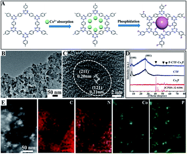
Fig. 1A shows the basic procedures for the preparation of CTF polymer anchored Co2P nanocrystals. Briefly, the CTFs with adsorbed cobalt ions were directly phosphatized by thermal decomposition of NaH2PO2 under an Ar atmosphere, which could simultaneously achieve P atom bonding with benzene rings and the anchoring of the Co2P cocatalyst (marked as P-CTF-Co2P). Fig. 1B shows the typical transmission electron microscopy (TEM) image of the obtained sample, clearly revealing that well-defined Co2P nanocrystals with an average diameter of 5∼9 nm were uniformly dispersed on the CTF surface. Furthermore, the high-resolution TEM (HR-TEM) image (Fig. 1C) of the formed nanocrystals exhibited two lattice fringes with d-spacing values of 0.20 and 0.21 nm, respectively, which could be well indexed to the (211) and (121) planes of orthorhombic Co2P crystals.36,37Fig. 1D shows the X-ray diffraction (XRD) pattern of the obtained P-CTF-Co2P sample. For comparison, the pristine CTF, and Co2P nanocrystals have also been studied. It can be clearly seen that for the P-CTF-Co2P sample, except for the two broad diffraction peaks at 7.3° and 26.1° attributed to the in-plane (100) facets and interlayer (001) stacking of CTFs,38,39 the other XRD peaks well matched with those of the Co2P crystals,40,41 confirming the successful incorporation of the Co2P cocatalyst in the CTFs. Furthermore, energy-dispersive X-ray (EDX) elemental mapping (Fig. 1E) clearly reveals the uniform distribution of C, N, Co and P elements in the whole detection region, further confirming the uniform dispersion of Co2P on CTF polymers.
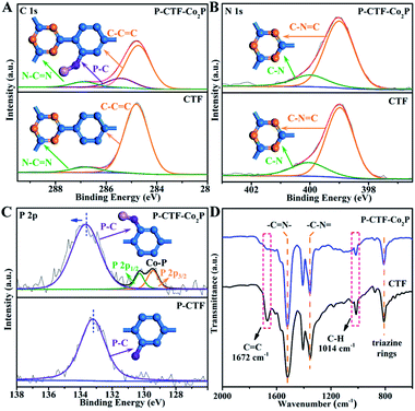
To further explore the P-bonding sites, high-resolution X-ray photoelectron spectroscopy (XPS) was performed on both P-CTF-Co2P and pristine CTFs. As shown in Fig. 2A, for pristine CTF samples, the C 1s peak could be well fitted into two peaks located at 284.8 and 286.8 eV, which could be assigned to C–C![[double bond, length as m-dash]](https://www.rsc.org/images/entities/char_e001.gif) C and N–C
C and N–C![[double bond, length as m-dash]](https://www.rsc.org/images/entities/char_e001.gif) N bonds,38,39,42 respectively. Notably, after the phosphidation treatment, a new peak at 285.3 eV attributed to P–C bonds was detected in the P-CTF-Co2P sample,43–45 and the C–C
N bonds,38,39,42 respectively. Notably, after the phosphidation treatment, a new peak at 285.3 eV attributed to P–C bonds was detected in the P-CTF-Co2P sample,43–45 and the C–C![[double bond, length as m-dash]](https://www.rsc.org/images/entities/char_e001.gif) C to N–C
C to N–C![[double bond, length as m-dash]](https://www.rsc.org/images/entities/char_e001.gif) N ratio was significantly decreased from 10.2 (pristine CTFs) to 7.1 (P-CTF-Co2P). In contrast, compared with the N 1s spectrum of the pristine CTF sample, no evident change of peak shape and intensity could be detected in the P-CTF-Co2P sample (Fig. 2B). These results clearly reveal that after the phosphidation treatment, P atoms should mainly bond with the carbon sites of the benzene rings in CTFs instead of the triazine rings.46,47 To further confirm this inference, XPS studies on phosphatized CTFs without Co2P nanocrystals (marked as P-CTFs) were also performed. It can be clearly seen from Fig. S9† that similar changes for the C 1s and N 1s peaks of P-CTF-Co2P (Fig. 2A and B) are observed in the P-CTF sample. Moreover, in both P-CTF-Co2P and P-CTF samples, an evident P 2p peak corresponding to P–C bonds could be observed (Fig. 2C),48 further indicating the bonding of P atoms with C atoms on the benzene rings in CTFs after the phosphidation treatment. However, note that the binding energy (BE) position of P–C peaks in P-CTF-Co2P (133.6 eV) is slightly higher than that of P-CTF (133.2 eV), which should be attributed to the anchoring with Co2P nanocrystals. In addition to the XPS investigations, solid-state cross-polarization magic angle spinning carbon-13 and phosphorus-31 nuclear magnetic resonance (13C-NMR and 31P-NMR) spectroscopy studies were further performed to explore the bonding sites of phosphorus atoms in the P-CTF (Fig. S10†). The Fourier-transformed infrared (FTIR) spectrum was also employed (Fig. 2D). It can be clearly observed that the typical FTIR peaks of the triazine frameworks and the stretching vibrations of carbon–nitrogen (C–N) (1521 cm−1 and 1354 cm−1) in P-CTF-Co2P are consistent with those of pristine CTFs.38,39 However, the peaks at 1672 cm−1 and 1014 cm−1 corresponding to the stretching vibrations of C
N ratio was significantly decreased from 10.2 (pristine CTFs) to 7.1 (P-CTF-Co2P). In contrast, compared with the N 1s spectrum of the pristine CTF sample, no evident change of peak shape and intensity could be detected in the P-CTF-Co2P sample (Fig. 2B). These results clearly reveal that after the phosphidation treatment, P atoms should mainly bond with the carbon sites of the benzene rings in CTFs instead of the triazine rings.46,47 To further confirm this inference, XPS studies on phosphatized CTFs without Co2P nanocrystals (marked as P-CTFs) were also performed. It can be clearly seen from Fig. S9† that similar changes for the C 1s and N 1s peaks of P-CTF-Co2P (Fig. 2A and B) are observed in the P-CTF sample. Moreover, in both P-CTF-Co2P and P-CTF samples, an evident P 2p peak corresponding to P–C bonds could be observed (Fig. 2C),48 further indicating the bonding of P atoms with C atoms on the benzene rings in CTFs after the phosphidation treatment. However, note that the binding energy (BE) position of P–C peaks in P-CTF-Co2P (133.6 eV) is slightly higher than that of P-CTF (133.2 eV), which should be attributed to the anchoring with Co2P nanocrystals. In addition to the XPS investigations, solid-state cross-polarization magic angle spinning carbon-13 and phosphorus-31 nuclear magnetic resonance (13C-NMR and 31P-NMR) spectroscopy studies were further performed to explore the bonding sites of phosphorus atoms in the P-CTF (Fig. S10†). The Fourier-transformed infrared (FTIR) spectrum was also employed (Fig. 2D). It can be clearly observed that the typical FTIR peaks of the triazine frameworks and the stretching vibrations of carbon–nitrogen (C–N) (1521 cm−1 and 1354 cm−1) in P-CTF-Co2P are consistent with those of pristine CTFs.38,39 However, the peaks at 1672 cm−1 and 1014 cm−1 corresponding to the stretching vibrations of C![[double bond, length as m-dash]](https://www.rsc.org/images/entities/char_e001.gif) C and C–H in benzene rings were evidently decreased in P-CTF-Co2P compared with those of pristine CTFs.49,50 Combining the results of XPS, NMR, and FTIR, it can be concluded that in the obtained P-CTF-Co2P sample, the carbon sites of the benzene rings in the CTFs were partially bonded with P-atoms, which should anchor Co2P through P–Co bonding.
C and C–H in benzene rings were evidently decreased in P-CTF-Co2P compared with those of pristine CTFs.49,50 Combining the results of XPS, NMR, and FTIR, it can be concluded that in the obtained P-CTF-Co2P sample, the carbon sites of the benzene rings in the CTFs were partially bonded with P-atoms, which should anchor Co2P through P–Co bonding.
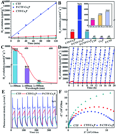
Furthermore, the hydrogen evolution activities of the P-CTF-Co2P (2 wt% Co2P) sample were evaluated under simulated solar light irradiation. For comparison, the CTF/Co2P composite and pristine CTFs were also measured under the same conditions. As shown in Fig. 3A, the P-CTF-Co2P sample exhibits a much higher H2 evolution activity (15.2 mmol g−1) than the CTF/Co2P composite (0.7 mmol g−1) at 2 h, while no evident hydrogen generation could be detected in the pristine CTF sample. To further explore the crucial roles of interfacial P-bonding in CTFs and the anchoring of the Co2P cocatalyst, the hydrogen evolution rates of various samples were calculated and their comparison is shown in Fig. 3B. Obviously, compared with the excellent activity of P-CTF-Co2P (7.6 mmol h−1 g−1), CTF/Co2P and P-CTF/Co2P only exhibit very low hydrogen evolution rates of 0.37 and 0.38 mmol h−1 g−1, respectively, while no evident activity could be detected for CTFs, Co2P, and P-CTF samples. The above results clearly confirm that the significant enhancement of the hydrogen evolution activity of the P-CTF-Co2P sample should be mainly attributed to the P-bonding and the anchoring of the Co2P cocatalyst. Furthermore, the photocatalytic performances of CTFs decorated with Pt nanoparticles were also studied (the inset of Fig. 3B, Fig. S15†), as Pt is generally recognized as the most active cocatalyst for hydrogen generation. Amazingly, the hydrogen production rates of the Pt cocatalyst at different amounts (1∼5 wt%) were all lower than that of the P-CTF-Co2P sample, indicating that the rational bonding of the Co2P cocatalyst on CTFs should be a promising strategy for achieving highly efficient photocatalytic hydrogen evolution.
Furthermore, the relationship between wavelength and the hydrogen evolution activity of the P-CTF-Co2P photocatalyst was studied and is shown in Fig. 3C. With increasing the wavelength from full-spectrum light irradiation (λ > 300) to 500 nm, the hydrogen evolution rate significantly decreased from 7.6 to 0.06 mmol h−1 g−1, which is generally consistent with their absorption spectrum. The highest value of the apparent quantum yields (AQYs) attained is 31.8% at 365 nm. Moreover, the photocatalytic stability and durability of P-CTF-Co2P and CTF/Co2P were examined by cycling experiments. As shown in Fig. 3D, the CTF/Co2P composite demonstrated relatively poor stability, and there is no evident activity after only one cycling experiment, resulting from the incompact combination between CTFs and Co2P (Fig. S5†). In contrast, the P-CTF-Co2P sample exhibits relatively high stability, and no evident inactivation was detected during the whole test. These results further confirm that in addition to enhancing activities, the interfacial P–C bonds and the anchoring of the Co2P cocatalyst could also effectively promote the hydrogen evolution stability. To further confirm the efficient charge separation and electron transfer in P-CTF-Co2P, photoelectrochemical (PEC) tests were performed. As shown in Fig. 3E, the amperometric I–t curves clearly reveal that P-CTF-Co2P exhibits higher photocurrent density than pristine CTFs and CTF/Co2P samples, confirming its more efficient charge separation capability. Moreover, electrochemical impedance spectroscopy (EIS) was also performed to explore the interfacial charge transfer process.51,52 As shown in Fig. 3F, the P-CTF-Co2P sample with the smallest arc radius revealed remarkably increased interfacial charge transport efficiency. These PEC results clearly demonstrate the highly efficient photogenerated charge separation and transfer in the P-CTF-Co2P photocatalyst, which are highly consistent with the above photocatalytic hydrogen evolution results.
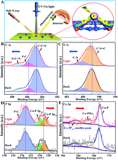
The photo-induced charge separation and transfer in the excited state are crucial processes for determining the photocatalytic activity. Herein, we have demonstrated an in situ irradiation X-ray photoelectron spectroscopy (SI-XPS) technique for exploring the intrinsic charge separation and transfer mechanisms between Co2P and CTFs. As shown in Fig. S20 and S21,† no evident binding energy (BE) shift could be observed in both pristine CTF and Co2P samples, confirming their relatively poor charge separation capability. Amazingly, for the P-CTF-Co2P sample (Fig. 4), distinct variations for C 1s, N 1s, P 2p, and Co 2p peaks were detected in the excited state. More specifically, the C 1s and N 1s peaks in the CTFs shifted towards the high BE region by 0.3 eV accompanied by the broadening of peak shape (Fig. 4B and C), while the P 2p and Co 2p peaks of the Co2P cocatalyst shifted towards the low BE direction by 0.3 and 0.4 eV (Fig. 4D and E), respectively.Interestingly, as shown in Fig. 4D, the P 2p peaks attributed to interfacial P–C bonds exhibited no evident BE change under dark and light irradiation. On the basis of the above SI-XPS results, it can be concluded that under light irradiation, the photo-excited electrons effectively transferred from CTFs to Co2P through the P-bonding sites as well as the interfacial P–C bonds, leading to electron enrichment in Co2P nanocrystals and hole enrichment in CTFs. To further confirm the crucial roles of interfacial P-bonding in CTFs and the anchoring of the Co2P cocatalyst in promoting charge separation, SI-XPS studies for the CTF/Co2P composite were also conducted. As shown in Fig. S22,† no new peak or shape change of C 1s, N 1s, P 2p, and Co 2p peaks could be detected in CTF/Co2P compared with pristine CTFs and Co2P in the ground state, indicating no interfacial bonding in the CTF/Co2P composite. Furthermore, in the excited state, no evident BE shifts and shape change could be observed, indicating the poor charge-separation capability of CTF/Co2P, which is highly consistent with its fairly low hydrogen evolution activity. These SI-XPS results further confirm the crucial roles of interfacial P-bonding in CTFs and the anchoring of the Co2P cocatalyst in efficiently promoting charge separation and enhancing the photocatalytic activity.
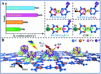
On the basis of the above results, it can be concluded that the P-bonding and Co2P-cocatalyst anchoring should reverse the photo-induced electron transfer direction from the triazine to benzene rings in CTFs. To further confirm this speculation, the photocatalytic behavior of various CTF-based photocatalysts was studied and their electron transfer directions in excitation states have been proposed (Fig. 5A and B). First, when Co2+ ions were further bonded with the N sites of the triazine rings in the P-CTF-Co2P sample (marked as P-CTF-Co2P-Co), the hydrogen evolution activity remarkably increased from 7.6 up to 8.4 mmol h−1 g−1. This result clearly reveals that the Co–N bonding in P-CTF-Co2P could further promote charge separation due to the effective hole trapping on Co sites. In contrast, when the Pt cocatalyst was decorated on the P-CTF-Co2P sample (marked as P-CTF-Co2P–Pt) to form Pt–N coordination, the photocatalytic activity significantly decreased to 4.6 mmol h−1 g−1, mainly resulting from the electron transfer competition between Pt and Co2P. Furthermore, the decoration of the single Pt cocatalyst on CTFs promoted the photo-induced electron transfer from the benzene rings to triazine rings, and the photocatalytic activity achieved was up to 3.8 mmol h−1 g−1. Furthermore, in situ FTIR spectroscopy was performed for exploring the intermediate products in the photocatalytic process of the P-CTF-Co2P sample with co-adsorption of H2O vapor (Fig. S27†), which also demonstrated the direction of electron transfer combined with the in situ XPS results. Accordingly, a possible mechanism has been proposed for clarifying the hydrogen evolution activities of the P-CTF-Co2P photocatalyst (Fig. 5B). Owing to the P-bonding and the anchoring of Co2P nanocrystals, the photo-generated electrons could effectively transfer from the triazine rings to benzene rings, where the electrons are trapped by the Co2P cocatalyst through the interfacial P–C bonds for the hydrogen evolution reaction. Simultaneously, the holes left behind in the CTFs participated in oxidation reactions. More importantly, this mechanism may provide a new insight for understanding the crucial roles of interfacial P-bonding in CTFs and their bonding with Co2P in promoting the charge separation for efficient hydrogen evolution.
Conclusions
In summary, we have reported a facile phosphidation strategy for anchoring Co2P nanocrystals on CTFs. More specifically, owing to the presence of interfacial P-bonding and the anchoring of Co2P, the electron transfer direction was changed in the CTF from the triazine rings to benzene rings, achieving efficient transfer from the CTF to Co2P surfaces through the interfacial P–C bonds. Accordingly, the enriched electrons on the Co2P cocatalyst could quickly participate in the hydrogen evolution reactions, while the holes remaining in the triazine rings of the CTF participated in oxidation reactions. Benefiting from these outstanding features, the P-CTF-Co2P photocatalyst achieved an excellent hydrogen evolution rate of 7.6 mmol h−1 g−1 accompanied by enhanced stability, one of the highest activities among all reported CTF-based photocatalysts with non-platinum cocatalysts. This work not only provides a unique insight for switching the charge transfer direction in conjugated polymers, but also highlights the crucial roles of interfacial bonding with HER cocatalysts, which should be important for developing highly efficient and stable photocatalysts.Data availability
All data are available in the main text or the ESI.†Author contributions
L. W. Z and Y. P. B conceived and designed the experiments. Y. M. Z prepared the covalent triazine-based framework sample. L. W. Z performed the photocatalytic measurement. X. J. H performed the XPS measurement. L. W. Z and Y. P. B wrote the paper. All authors reviewed the paper.Conflicts of interest
There are no conflicts to declare.Acknowledgements
The work was supported by the National Natural Science Foundation of China (21832005, 22072168, 22002175), Strategic Priority Research Program of the Chinese Academy of Sciences (XDA21061011), and Major Program of the Lanzhou Institute of Chemical Physics, CAS (No. ZYFZFX-3). The authors appreciate the assistance of Dr Yao Xiao and Prof. Anmin Zheng for the NMR measurements.Notes and references
- R. M. Navarro, M. C. Sánchez-Sánchez, M. C. Alvarez-Galvan, F. d. Valle and J. L. G. Fierro, Energy Environ. Sci., 2009, 2(1), 35–54 RSC.
- X. Zou and Y. Zhang, Chem. Soc. Rev., 2015, 44(15), 5148–5180 RSC.
- J. Ran, J. Zhang, J. Yu, M. Jaroniec and S. Z. Qiao, Chem. Soc. Rev., 2014, 43(22), 7787–7812 RSC.
- J. Qi, W. Zhang and R. Cao, Adv. Energy Mater., 2018, 8(5), 1701620 CrossRef.
- M. M. May, H. J. Lewerenz, D. Lackner, F. Dimroth and T. Hannappel, Nat. Commun., 2015, 6, 8286 CrossRef CAS PubMed.
- L. Wang, Y. Zhang, L. Chen, H. Xu and Y. Xiong, Adv. Mater., 2018, 1801955 CrossRef.
- L. Wang, Y. Wan, Y. Ding, S. Wu, Y. Zhang, X. Zhang, G. Zhang, Y. Xiong, X. Wu, J. Yang and H. Xu, Adv. Mater., 2017, 1702428 CrossRef PubMed.
- L. Stegbauer, K. Schwinghammer and B. V. Lotsch, Chem. Sci., 2014, 5(7), 2789–2793 RSC.
- P. Katekomol, J. Roeser, M. Bojdys, J. Weber and A. Thomas, Chem. Mater., 2013, 25(9), 1542–1548 CrossRef CAS.
- Q. Yang, M. Luo, K. Liu, H. Cao and H. Yan, Appl. Catal., B, 2020, 276 Search PubMed.
- Z. Lan, X. Chi, M. Wu, X. Zhang, X. Chen, G. Zhang and X. Wang, Small, 2022, 18, 2200129 CrossRef CAS PubMed.
- Y. Fang, Y. Hou, X. Fu and X. Wang, Chem. Rev., 2022, 122, 4204–4256 CrossRef CAS.
- S. Kuecken, A. Acharjya, L. Zhi, M. Schwarze, R. Schomacker and A. Thomas, Chem. Commun., 2017, 53(43), 5854–5857 RSC.
- D. Kong, X. Han, J. Xie, Q. Ruan, C. D. Windle, S. Gadipelli, K. Shen, Z. Bai, Z. Guo and J. Tang, ACS Catal., 2019, 9(9), 7697–7707 CrossRef CAS.
- C. B. Meier, R. Clowes, E. Berardo, K. E. Jelfs, M. A. Zwijnenburg, R. S. Sprick and A. I. Cooper, Chem. Mater., 2019, 31(21), 8830–8838 CrossRef CAS PubMed.
- J. Kibsgaard, C. Tsai, K. Chan, J. D. Benck, J. K. Nørskov, F. Abild-Pedersen and T. F. Jaramillo, Energy Environ. Sci., 2015, 8(10), 3022–3029 RSC.
- Y. Shi and B. Zhang, Chem. Soc. Rev., 2016, 45(6), 1529–1541 RSC.
- Y. Shi, M. Li, Y. Yu and B. Zhang, Energy Environ. Sci., 2020, 13, 4564 RSC.
- J. Xu, J. Li, D. Xiong, B. Zhang, Y. Liu, K. Wu, I. Amorim, W. Li and L. Liu, Chem. Sci., 2018, 9, 3470–3476 RSC.
- Z. Hu, Z. Shen and J. C. Yu, Green Chem., 2017, 19, 588 RSC.
- K. Wu, P. Wu, J. Zhu, C. Liu, X. Dong, J. Wu, G. Meng, K. Xu, J. Hou, Z. Liu and X. Guo, Chem. Eng. J., 2019, 360, 221–230 CrossRef CAS.
- Y. Liu, A. McCue, C. Miao, J. Feng, D. Li and J. Anderson, J. Catal., 2018, 364, 406–414 CrossRef CAS.
- P. Zhou, Q. Zhang, Z. Xu, Q. Shang, L. Wang, Y. Chao, Y. Li, H. Chen, F. Lv, Q. Zhang, L. Gu and S. Guo, Adv. Mater., 2020, 32, 1904249 CrossRef CAS.
- Y. Li, M. Qi, J. Li, Z. Tang and Y. Xu, Appl. Catal., B, 2019, 257, 117934 CrossRef CAS.
- T. Uekert, H. Kasap and E. Reisner, J. Am. Chem. Soc., 2019, 141, 15201 CrossRef CAS PubMed.
- H. Dong, M. Xiao, S. Yu, H. Wu, Y. Wang, J. Sun, G. Chen and C. Li, ACS Catal., 2020, 10, 458–462 CrossRef CAS.
- K. Sun, M. Liu, J. Pei, D. Li, C. Ding, K. Wu and H. L. Jiang, Angew. Chem., Int. Ed. Engl., 2020, 59(50), 22749–22755 CrossRef CAS.
- L. Yan, L. Cao, P. Dai, X. Gu, D. Liu, L. Li, Y. Wang and X. Zhao, Adv. Funct. Mater., 2017, 27, 1703455 CrossRef.
- J.-D. Yi, R. Xu, G.-L. Chai, T. Zhang, K. Zang, B. Nan, H. Lin, Y.-L. Liang, J. Lv, J. Luo, R. Si, Y.-B. Huang and R. Cao, J. Mater. Chem. A, 2019, 7(3), 1252–1259 RSC.
- J.-D. Yi, R. Xu, Q. Wu, T. Zhang, K.-T. Zang, J. Luo, Y.-L. Liang, Y.-B. Huang and R. Cao, ACS Energy Lett., 2018, 3(4), 883–889 CrossRef CAS.
- P. Su, K. Iwase, T. Harada, K. Kamiya and S. Nakanishi, Chem. Sci., 2018, 9, 3941 RSC.
- Z. Pu, T. Liu, I. S. Amiinu, R. Cheng, P. Wang, C. Zhang, P. Ji, W. Hu, J. Liu and S. Mu, Adv. Funct. Mater., 2020, 30, 2004009 CrossRef CAS.
- H. Zhang, A. W. Maijenburg, X. Li, S. L. Schweizer and R. B. Wehrspohn, Adv. Funct. Mater., 2020, 30, 2003261 CrossRef CAS.
- D. Zeng, W.-J. Ong, H. Zheng, M. Wu, Y. Chen, D.-L. Peng and M.-Y. Han, J. Mater. Chem. A, 2017, 5(31), 16171–16178 RSC.
- Z. Pan, Y. Zheng, F. Guo, P. Niu and X. Wang, ChemSusChem, 2017, 10(1), 87–90 CrossRef CAS.
- R. Jin, X. Li, Y. Sun, H. Shan, L. Fan, D. Li and X. Sun, ACS Appl. Mater. Interfaces, 2018, 10(17), 14641–14648 CrossRef CAS PubMed.
- H. Liu, J. Guan, S. Yang, Y. Yu, R. Shao, Z. Zhang, M. Dou, F. Wang and Q. Xu, Adv. Mater., 2020, 32(36), 2003649 CrossRef CAS.
- M. Liu, Q. Huang, S. Wang, Z. Li, B. Li, S. Jin and B. Tan, Angew. Chem., Int. Ed., 2018, 57(37), 11968–11972 CrossRef CAS PubMed.
- K. Wang, L. Yang, X. Wang, L. Guo, G. Cheng, C. Zhang, S. Jin, B. Tan and A. Cooper, Angew. Chem., Int. Ed., 2017, 56, 14149–14153 CrossRef CAS PubMed.
- Y. Men, P. Li, J. Zhou, G. Cheng, S. Chen and W. Luo, ACS Catal., 2019, 9, 3744–3752 CrossRef CAS.
- D. Das and K. K. Nanda, Nano Energy, 2016, 30, 303–311 CrossRef CAS.
- S. Y. Yu, J. Mahmood, H. J. Noh, J. M. Seo, S. M. Jung, S. H. Shin, Y. K. Im, I. Y. Jeon and J. B. Baek, Angew. Chem., Int. Ed., 2018, 57(28), 8438–8442 CrossRef CAS PubMed.
- L. Jing, R. Zhu, D. L. Phillips and J. C. Yu, Adv. Funct. Mater., 2017, 27(46), 1703484 CrossRef.
- Y. Zheng, S. Chen, K. A. I. Zhang, J. Zhu, J. Xu, C. Zhang and T. Li, ACS Appl. Mater. Interfaces, 2021, 13, 13328–13337 CrossRef CAS PubMed.
- Z. Cheng, W. Fang, T. Zhao, S. Fang, J. Bi, S. Liang, L. Li, Y. Yu and L. Wu, ACS Appl. Mater. Interfaces, 2018, 10, 41415–41421 CrossRef CAS PubMed.
- S. N. Talapaneni, T. H. Hwang, S. H. Je, O. Buyukcakir, J. W. Choi and A. Coskun, Angew. Chem., Int. Ed., 2016, 55, 3106–3111 CrossRef CAS PubMed.
- L. Li, W. Fang, P. Zhang, J. Bi, Y. He, J. Wang and W. Su, J. Mater. Chem. A, 2016, 4, 12402 RSC.
- Y. Qian, S. Jiang, Y. Li, Z. Yi, J. Zhou, T. Li, Y. Han, Y. Wang, J. Tian, N. Lin and Y. Qian, Adv. Energy Mater., 2019, 9(34), 1901676 CrossRef.
- N. Fuson, M. Josien and E. M. Shelton, J. Am. Chem. Soc., 1954, 76(9), 2526–2533 CrossRef CAS.
- W. Wu, L. Liao, C. Lien and J. Lin, Phys. Chem. Chem. Phys., 2001, 3, 4456–4461 RSC.
- X. Cheng, Y. Zhang, H. Hu, M. Shang and Y. Bi, Nanoscale, 2018, 10(8), 3644–3649 RSC.
- M. Zhang, J. Wang, H. Xue, J. Zhang, S. Peng, X. Han, Y. Deng and W. Hu, Angew. Chem., Int. Ed., 2020, 59, 18463–18467 CrossRef CAS.
Footnote |
| † Electronic supplementary information (ESI) available: Experimental procedure, and additional data containing TEM, XRD, NMR, and SI-XPS measurements. See https://doi.org/10.1039/d2sc02638d |
| This journal is © The Royal Society of Chemistry 2022 |

