DOI:
10.1039/D2RA05594E
(Paper)
RSC Adv., 2022,
12, 32110-32118
Development of efficient bi-functional g-C3N4@MOF heterojunctions for water splitting†
Received
5th September 2022
, Accepted 21st October 2022
First published on 10th November 2022
Abstract
Herein we report the development of highly efficient heterojunctions by combining n-type g-C3N4 and MOFs as bi-functional photoelectrocatalysts towards the hydrogen evolution reaction (HER) and the oxygen evolution reaction (OER). g-C3N4@MIL-125(Ti) and g-C3N4@UiO-66 have been synthesized via in situ incorporation of pre-synthesized g-C3N4 nanoparticles into MIL-125(Ti) and UiO-66. Bare MIL-125(Ti) and UiO-66 are also prepared for comparison. All the synthesized samples have been characterized by Powder X-ray Diffraction analysis, Fourier Transform Infrared Spectroscopic analysis, Scanning Electron Microscopic analysis, Energy Dispersive X-ray Spectrometry and UV-Vis Spectroscopic analysis. Cyclic voltammetry and linear sweep voltammetry studies have been carried out for all samples which indicates that under visible light exposure the g-C3N4@MIL-125(Ti)/NF heterojunction achieved a current density of 10 mA cm−2 at just 86 and 173 mV overpotential for the HER and OER, respectively. Moreover, all the synthesized samples display significant stability and generate a constant current density up to 1000 cyles during water electrolysis performed at a constant applied potential 1.5 V.
Introduction
In order to address the need for renewable and safe energy conversion and storage, water splitting into hydrogen and oxygen is considered to be one of the most significant and efficient technologies.1 Water splitting comprises two half-reactions: the hydrogen evolution reaction (HER) at the cathode and the oxygen evolution reaction (OER) at the anode.2 A high over-potential is required to split water into hydrogen (HER) and oxygen (OER). In particular, the OER is considered a serious bottleneck to facilitate effective water splitting due to its high over-potential and poor kinetics, which are mainly due to multi-step proton coupled electron transfer reactions.3–5 State of the art catalysts for water splitting are noble metal-based, and among them RuO2 and IrO2 based materials are used for the OER and Pt-based catalysts are used for the HER.6–8 However, their extreme shortage and high costs have seriously diminished their commercial application.9,10 Therefore a substantial amount of work has been done on the design and development of highly effective, noble metal free bi-functional catalysts for the HER and the OER, for example, heteroatom (N, P, S, Fe, Co, etc.) doped carbon materials, metal and nitrogen doped carbon (M–N–C), transition metal oxides, etc.11–13 In particular, M–N–C catalysts have arisen as a promising alternative to noble metal based catalysts due to their unique structural properties of metal coordinated surface nitrogen.14
These materials can be synthesized using various methods. One of the various methods for the preparation of M–N–C catalysts is the formation of hetero junctions between metal organic frameworks (MOFs) and g-C3N4 by means of the in situ incorporation.15 MOFs are porous crystalline materials which are metabolized by the coordination of metal ion or metal clusters with organic moiety. In MOFs, both metal nodes and organic connectors are classified as isolated quantum dots and light absorption antenna, respectively.16–19 Both metal nodes and organic connectors take part in photocatalytic reactions. Metal nodes can be directly stimulated by light irradiation or activated by an organic link.20
Recently, metal free graphene based mesoporous carbon has proven to be cost effective and robust catalyst. Graphitic carbon nitride (g-C3N4) is a metal free n-type semiconductor and has been revealed to be a valuable catalyst under visible light due to its narrow band gap, excellent stability, fast charge transfer and easy availability of raw material for its synthesis.21–25 However, g-C3N4 has one limitation of high recombination of the photo induced e−/h+ pair which adversely affects its catalytic activity.26 Though both MOFs and g-C3N4 have been recorded as effective catalysts, their performance still seems to be poor and researchers are working on a number of techniques to increase their performance. Among other methods, heterojunction production using n-type g-C3N4 and MOFs is a successful tool for reducing the rate of recombination of photo induced electron hole pairs and increasing photocatalytic activity under visible light.27 Numerous excellent heterojunctions have been reported which delivers 10 mA cm−2 current density for HER and OER at low overpotential such as CuO@UiO-66/NF (ƞ10 = 220 mV HER), CuO@MIL-125(Ti)/NF (ƞ10 = 186 and 353 mV for HER and OER, respectively), MoS2/g-C3N4 and Cl–CuO/g-C3N4.28–31
In view of these findings, highly efficient heterojunctions have been developed by combining n-type g-C3N4 and MOFs (MIL-125(Ti) and UiO-66) via in situ incorporation. It has been found that g-C3N4@MIL-125(Ti)/NF heterojunction has effectively reduces the band gap, increases the absorption of visible light, reduces the rate of recombination of electron hole pair and under visible light exposure delivers 10 mA cm−2 at just 86 and 173 mV overpotential for HER and OER respectively.
Experimental
Materials
The chemicals used for synthesis of materials are urea (NH2CONH2, 99.00%); 1, 4-benzendicarboxylic acid (H2BDC, 99%); titanium isopropoxide (Ti[OCH(CH3)2]4, 99%); zirconium(IV) chloride (ZrCl4, 99.99%); N,N-dimethylformamide (DMF, 99.8%) and methanol (CH3OH, 99.9%).
Synthesis of g-C3N4
g-C3N4 was prepared by pyrolysis of urea.32 In a typical reaction, 10 g of urea was taken in a covered crucible and put in Muffle furnace at 550 °C for 3 h. After that, the crucible was cooled to room temperature and yellow colored precipitates were obtained, which were stored for further process (Fig. 1).
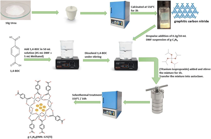 |
| | Fig. 1 A systematic representation of synthesis of g-C3N4@MIL-125(Ti). | |
Development of g-C3N4@MIL-125(Ti) and g-C3N4@UiO-66 heterojunction
Solvothermal process was used for the development of g-C3N4@MIL-125(Ti) and g-C3N4@UiO-66 heterojunction via in situ introduction of pre-synthesized g-C3N4 into host MOFs. For g-C3N4@MIL-125(Ti), 15 mmol (2.62 g) of 1,4-benzendicarboxylic acid was dissolved in 50 mL solution of N,N-dimethylformamide and methanol (45 + 5 mL, respectively), followed by a dropwise addition of 10 mL DMF suspension of 0.2 g g-C3N4 under constant stirring. After that, 0.45 mmol (0.13 g) of titanium isopropoxide was introduced to the above mixture and stirred for 1 hour. The mixture was then moved to Teflon lined stainless steel autoclave and heated in an oven at 150 °C for 16 hours. At the end, the precipitates were obtained, isolated by centrifugation, washed with DMF and methanol, and dried in an oven at 100 °C under vacuum.
g-C3N4@UiO-66 was also synthesized via above mentioned solvothermal by using zirconium(IV) chloride instead of titanium isopropoxide. For comparison bare MIL-125(Ti) and UiO-66 was also prepared by following same procedure without addition of g-C3N4.
Fabrication of working electrode
To study the HER and OER, working electrodes were fabricated by pasting slurry of photocatalytic material on 1 cm2 pieces of nickel foam (NF). Slurry was prepared by sonicating 0.10 g of synthesized material in 1 mL distilled water. The slurry was uniformly pasted on cleaned piece of NF and dried to fabricate working electrodes.
Characterization of synthesized materials
The crystal structure of synthesized specimens was studied by taking powder XRD patterns on Shimadzu XRD diffractometer over a 2θ range of 5°–80°. Infrared spectra were measured by using Nicolet Nexus 870 spectrometer in the range of 4000–400 cm−1. Raman spectra of all synthesized materials were measured by using Jobin-Yvon LabRAM HR800 Raman spectrometer with helium neon laser (532.02 nm) in the range of 100–2000 cm−1. The morphology and composition were studied by using Philips XL30 Environmental SEM attached with Oxford Instrument Inca 500 Energy Dispersive X-ray spectrometer (EDX). UV-Visible spectroscopy was performed via Shimadzu UV-2600 spectrophotometer and UV-Visible spectra were recorded between 200 and 900 nm.
Hydrogen and oxygen evolution reaction studies
Photoelectrochemical tests for HER and OER were carried out by using a traditional three electrode device consisting of a working electrode, Pt as a counter electrode and Ag/AgCl (3 M KCl) as a reference electrode. 1.0 M KOH solution was used as electrolyte. Photoelectrochemical tests were performed through a Potentiostat/Galvanostat (Uniscan instruments 3100) at room temperature under dark and in the presence of sunlight. Sunlight was used as a source of visible energy. Cyclic voltammetry (CV) and linear sweep voltammetry (LSV) were conducted for both HER and OER at 10 and 1 mV s−1, respectively. All potential data collected were transformed to reversible hydrogen electrode (RHE) by using given equation.| | |
ERHE = EAg/AgCl + 0.197 + 0.059 pH
| (1) |
Overpotential (ƞ) for HER and OER was found through following equations
Long term stability of some selected synthesized catalysts was examined by means of 1000 repeated CV sweeps and chronoamperometric tests at a steady applied voltage of 1.5 V in the presence of visible light for 600 minutes.
Result and discussion
Powder XRD analysis
The powder XRD patterns of g-C3N4, MIL-125(Ti), UiO-66, g-C3N4@MIL-125(Ti) and g-C3N4@UiO-66 are shown in Fig. 2. The powder XRD pattern of g-C3N4 contains a well-defined diffraction peak at about 27.45° 2θ which is indexed to aromatic conjugated system of g-C3N4 and matched well with previously reported patterns and JCPDS card number 85-1526 (ref. 33). The powder XRD pattern of bare MIL-125(Ti) matched well with simulated pattern. Similarly, the PXRD pattern of UiO-66 is matched well with the simulated pattern. However, after the incorporation of the g-C3N4, all the diffraction peaks in the g-C3N4@MIL-125(Ti) and g-C3N4@UiO-66 are matched well with simulated patterns. The incorporation of g-C3N4 in MOFs does not influence the crystal structure of host MOFs and MOFs maintain their integrity and dominance. The characteristic diffraction peaks of incorporated g-C3N4 are overlaid by MOFs. However an additional peak at 27.45° 2θ is also observed in the PXRD pattern of C3N4@MIL-125(Ti) which may corresponds to g-C3N4. On careful analysis it has been observed that a small peak around 27.50° 2θ is also present in the PXRD pattern of MIL-125(Ti). It is possible that the peak near 27.45° 2θ overlie with the peak for g-C3N4 which results in the increase in intensity of this peak.
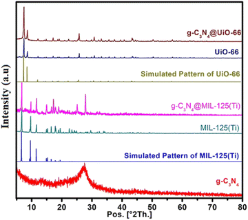 |
| | Fig. 2 Powder XRD patterns of g-C3N4, MIL-125(Ti), UiO-66, g-C3N4@MIL-125(Ti) and g-C3N4@UiO-66 in comparison with simulated patterns of MIL-125(Ti) and UiO-66. | |
FTIR and Raman analysis
Fig. 3(a) shows the FTIR spectra of all synthesized materials. FTIR spectrum of g-C3N4 contains a distinct peak at 810 cm−1 which belongs to triazine ring of g-C3N4. While, the peaks between 1200 cm−1 and 1650 cm−1 (1233, 1317, 1402, 1553 and 1635 cm−1) are due to typical stretching modes of CN heterocycles.34,35 FTIR spectra of both MIL-125(Ti) and g-C3N4@MIL-125(Ti) contain characteristic vibrational peaks of carboxylate group between 1300 and 1700 cm−1 and O–Ti–O vibrations between 400 and 800 cm−1 (ref. 36).
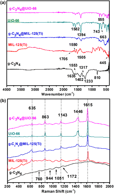 |
| | Fig. 3 (a) FTIR spectra and (b) Raman spectra of g-C3N4, MIL-125(Ti), UiO-66, g-C3N4@MIL-125(Ti) and g-C3N4@UiO-66. | |
Similarly, FTIR spectra of UiO-66 and g-C3N4@UiO-66 contain vibrational peaks corresponding to carboxylate group between 1300 and 1700 cm−1 and vibrational peaks of –OH, –CH of organic linker and Zr-(OC) at 743, 663 and 555 cm−1 respectively. Fig. 3(b) shows the Raman spectra of all synthesized samples. Small broad characteristic peaks are found at 588, 760, 944, 1051, 1172, cm−1 in the Raman spectra of g-C3N4 are attributed to the different types of ring breathing modes of triazine.37 Raman spectra of MIL-125(Ti), UiO-66, g-C3N4@MIL-125(Ti) and g-C3N4@UiO-66 consist on five typical vibrational bands at 1615, 1446, 1143, 863 and 635 cm−1 corresponding to stretching and bending vibrations of carboxylate group and C![[double bond, length as m-dash]](https://www.rsc.org/images/entities/char_e001.gif) C, C–H vibrations of benzene ring of organic ligand. However, it is observed that in both FTIR and Raman spectra of g-C3N4@MIL-125(Ti) and g-C3N4@UiO-66, vibrational peaks of g-C3N4 are not observed which indicates that the host MOFs dominate the g-C3N4 and both of them are close to each other due to physical and electrostatic interactions.
C, C–H vibrations of benzene ring of organic ligand. However, it is observed that in both FTIR and Raman spectra of g-C3N4@MIL-125(Ti) and g-C3N4@UiO-66, vibrational peaks of g-C3N4 are not observed which indicates that the host MOFs dominate the g-C3N4 and both of them are close to each other due to physical and electrostatic interactions.
Morphological and compositional analysis
Morphological and compositional analysis of all synthesized samples have been carried out by SEM and SEM based EDX which are shown in Fig. 4(a–e). Fig. 4(a) shows the SEM image of g-C3N4 which indicates that the g-C3N4 is grown in spherical form with agglomeration. MIL-125(Ti) and g-C3N4@MIL-125(Ti) have grown in cubic crystalline form and uniformly distributed which are represented in Fig. 4(b and c). While, UiO-66 and g-C3N4@UiO-66 have grown in irregular block shaped crystals and are uniformly distributed as shown in Fig. 4(d and e). Some variations in size have been observed after incorporation of g-C3N4 in MIL-125(Ti) and UiO-66. Fig. S1† shows the EDX images of all synthesized samples. EDX image of g-C3N4 consists of peaks of both C and N as shown in Fig. S1(a).† While, EDX images of MIL-125(Ti), g-C3N4@MIL-125(Ti), UiO-66 and g-C3N4@UiO-66 contain basic diffraction peaks of MIL-125(Ti) (Ti, C and O) and UiO-66 (Zr, C and O) as well as diffraction peaks of g-C3N4 respectively which are represented in Fig. S1(b–e).† To further investigate the distribution of incorporated g-C3N4 in MOFs, the elemental mapping is performed. Mix elemental maps of g-C3N4@MIL-125(Ti) and g-C3N4@UiO-66 reveal that g-C3N4 is successfully incorporated and uniformly distributed as represented in Fig. S2.†
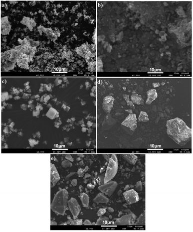 |
| | Fig. 4 SEM images of (a) g-C3N4; (b) MIL-125(Ti); (c) g-C3N4@MIL-125(Ti); (d) UiO-66 and (e) g-C3N4@UiO-66. | |
Optical properties
The UV-Vis absorption spectra of g-C3N4, pure MOFs and their heterojunctions g-C3N4@MIL-125(Ti) and g-C3N4@UiO-66 are represented in Fig. 5(a). The g-C3N4 exhibits an absorption edge upto 456 nm due to π → π* transition of conjugated triazine units.38 In pure MIL-125(Ti) absorption edge is up to 390 nm due to ligand-to-metal charge transfer while in g-C3N4@MIL-125(Ti) it extends to 467 nm. Similarly, in pure UiO-66 absorption edge is up to 328 nm while in g-C3N4@UiO-66 it extends to 450 nm. It indicates that incorporation of g-C3N4 in MOFs, affects the optical properties positively and brings the absorption of light from UV to visible region. It improves the utilization of solar energy, produces more electron–hole pair and increases the charge separation via heterojunction formation between g-C3N3 and central metallic cluster of MOFs. The band gap shown in Fig. 5(b) is determined from the plots of (αhν)2 versus photon energy (hν). The band gap is 2.85, 3.33, 2.90, 3.97 and 3.74 eV and for g-C3N4, MIL-125(Ti), g-C3N4@MIL-125(Ti), UiO-66 and g-C3N4@UiO-66 respectively. It shows that incorporated materials have band gaps in between of precursor's, so they have hybrid nature and can decrease the photo driving force for water splitting into hydrogen and oxygen via heterojunction formation.
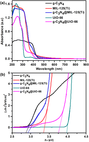 |
| | Fig. 5 (a) UV-Visible spectra and (b) full range plot of (αhν)2 verses hν of g-C3N4, MIL-125(Ti), UiO-66, g-C3N4@MIL-125(Ti) and g-C3N4@UiO-66. | |
Photoelectrochemical hydrogen evolution reaction analysis
All the prepared samples are used for the study of hydrogen evolution reaction (HER) via photoelectrochemical water splitting. Photoelectrochemical studies are performed via cyclic voltammetry (CV), linear sweep voltammetry (LSV) and chronoamperometric measurements. Firstly, CV is performed both in dark as well as in presence of visible light within potential range −0.2 to 0.2 V vs. RHE at 10 mV s−1 scan rate as shown in Fig. 6(a). CV curves show almost zero current density generation under dark because no HER observed. While, remarkable generation of current density is observed under visible light illumination due to HER. It can also be seen that incorporated materials show greater current density generation as compared to bare MOFs and g-C3N4. Further, photoelectrochemical activity towards HER is analyzed via LSV within potential range −0.2 to 0.2 V vs. RHE at 1 mV s−1 scan rate as shown in Fig. 6(b). Like CV, LSV is performed both under dark and in presence of visible light. In dark, no HER activity is observed and therefore, almost zero current density is generated. However, under solar light illumination, HER activity is observed and tremendous hydrogen gas bubbling is observed at surface of working electrode.
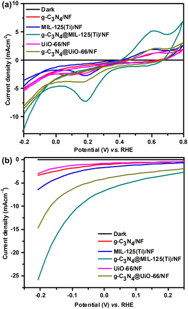 |
| | Fig. 6 (a) CV and (b) LSV curves of g-C3N4/NF, MIL-125(Ti)/NF, g-C3N4@MIL-125-(Ti)/NF, UiO-66/NF and g-C3N4/UiO-66/NF respectively. | |
CV curves show that, the maximum photoelectrochemical activity towards HER is shown by g-C3N4@MIL-125(Ti)/NF and it generated −12.83 mA cm−2 current density at RHE potential −0.20 V as compared to MIL-125(Ti) (−4.81 mA cm−2), UiO-66/NF (−5.55 mA cm −2), g-C3N4@UiO-66/NF (−8.88 mA cm−2) and g-C3N4/NF (−5.14 mA cm−2). Like CV, LSV curves also reveal that among all the synthesized materials, g-C3N4@MIL-125(Ti) exhibits maximum HER activity and delivers maximum current density −25.8 mA cm−2 at 206 mV overpotential as compared to g-C3N4@UiO-66 (−14.7 mA cm−2), g-C3N4 (−3.36 mA cm−2), MIL-125(Ti) (−6.45 mA cm−2) and UiO-66 (−2.94 mA cm−2). These results indicate that incorporation of g-C3N4 has promotionary effected over photocatalytic activity of MOF's and therefore, incorporated materials have better HER activity as compared to individual materials due to heterojunction development between g-C3N4 and MOFs.
The maximum HER activity is shown by g-C3N4@MIL-125(Ti) and it delivers −10 mA cm−2 current density at just 86 mV overpotential as compared to g-C3N4@UiO-66 (η10 = 186 mV) and previously reported g-C3N4 and MOFs based HER catalysts. A brief comparison of HER activity of g-C3N4@MIL-125(Ti) with different reported g-C3N4@MIL-125(Ti) with different reported C3N4-based, transition metal based and MOFs catalysts is given in Table 1. From CV and LSV curves, it is evaluated that g-C3N4@MIL-125(Ti) exhibited better and enhanced HER activity as compared to all other synthesized materials due to heterojunction development.
Table 1 Comparison of HER activity of g-C3N4@MIL-125(Ti) with different reported C3N4-based, transition metal based and MOFs catalysts
| Catalyst |
Current density (mA cm−2) |
Overpotential (ƞ) at corresponding current density (mV) |
Reference |
| C3N4/FTO: fluorine-doped tin oxide |
10 |
300 |
39 |
| N-GMT: nitrogen-doped graphene microtubes |
10 |
464 |
40 |
| CoMn-LDH@g-C3N4 |
50 |
448 |
41 |
| Cu2O/g-C3N4 |
12.8 |
148.7 |
42 |
| C3N4–CNT–CF |
10 |
131 |
43 |
| g-C3N4 QDs |
10 |
208 |
44 |
| g-C3N4-graphene hybrids |
10 |
207 |
45 |
| Sulfur-doped g-C3N4 |
10 |
145 |
46 |
| Fe0.2Co0.8Se2/g-C3N4 |
20 |
83 |
47 |
| UiO-66/MoS2 |
10 |
129 |
48 |
| MoP@PC |
10 |
153 |
49 |
| CuO@UiO-66/NF |
10 |
220 |
29 |
| CuO@NH2-UiO-66/NF |
10 |
166 |
50 |
| CuO@NH2-MIL-125(Ti)/NF |
5 |
146 |
28 |
| g-C3N4@UiO-66/NF |
10 |
186 |
This work |
| g-C3N4@MIL-125(Ti) |
10 |
86 |
This work |
Photoelectrochemical oxygen evolution traction analysis
Further, all the prepared samples are used for oxygen evolution (OER) analysis. OER measurements are performed by using linear sweep voltammetry (LSV) in dark as well as in the presence of visible light, represented in Fig. 7.
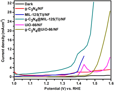 |
| | Fig. 7 LSV curves of g-C3N4/NF, MIL-125(Ti)/NF, g-C3N4@MIL-125-(Ti)/NF, UiO-66/NF and g-C3N4/UiO-66/NF respectively. | |
Fig. 7 shows that in dark, negligible current density is generated due to very less activity. While under illumination, all the synthesized materials show better OER activity. Among all the synthesized materials, g-C3N4@MIL-125(Ti)/NF shows maximum OER activity and it shows lowest onset OER potential and delivers 10 mA cm−2 current density at just 173 mV overpotential. It is lower than 310 mV for g-C3N4@UiO-66/NF and some of the previously reported OER catalysts, as given in Table 2. It has been found that g-C3N4@MIL-125(Ti)/NF generated maximum current density 32.50 mA cm−2 at 236 mV overpotential as compared to g-C3N4@UiO-66 (28.58 mA cm−2), g-C3N4 (3.19 mA cm−2), MIL-125(Ti) (9 mA cm−2) and UiO-66 (8.56 mA cm−2) at same overpotential. Like HER, it has been observed that incorporation of g-C3N4 has promotionary effect for OER activity. So, incorporation of g-C3N4 increases the photocatalytic activity of MOFs towards both HER and OER, thus synthesized materials show bifunctional photocatalytic activity.
Table 2 Comparison of OER activity of g-C3N4@MIL-125(Ti) with different reported C3N4-based, transition metal based and MOFs catalysts
| Catalyst |
Current density (mA cm−2) |
Overpotential (ƞ) at corresponding current density (mV) |
Reference |
| CoWO4 |
10 |
810 |
51 |
| CoMoO4 |
10 |
765 |
51 |
| 21 wt% WCoMoO4 |
10 |
680 |
51 |
| CoWO4/GC |
10 |
388 |
52 |
| CoWO4/Ni |
10 |
336 |
52 |
| Co0.5Mn0.5WO4 |
10 |
400 |
53 |
| FeCoNiOx |
10 |
203 |
54 |
| CS-NiFe0.10Cr0.10 on Cu |
10 |
200 |
55 |
| NiCo2O4/NiO |
10 |
360 |
56 |
| N–NiFeOOH |
10 |
320 |
57 |
| Co0.5Fe0.125Mn0.375WO4 |
10 |
460 |
58 |
| Fe0.2Co0.8Se2/g-C3N4 |
10 |
230 |
47 |
| CuO@NH2–UiO-66/NF |
10 |
283 |
50 |
| UiO-66/MoS2 |
10 |
180 |
48 |
| CoMn-LDH@g-C3N4 |
40 |
350 |
41 |
| CoOx/UiO-66-3000 |
10 |
283 |
59 |
| g-C3N4@MIL-125(Ti) |
10 |
173 |
This work |
Stability of catalysts and proposed photocatalytic mechanism
The stability of working electrode is very important factor for photoelectrochemical studies. The stability of electrode is another important factor and it was studied for the sample g-C3N4@MIL-125(Ti) by continuous 1000 CV cycles at 100 mV s−1 scan rate. It was observed that 1st and 1000th CV cycles almost overlapped with each other and there was very negligible degradation in current density. It indicated that these working electrodes were quite stable towards HER, represented by Fig. S3 in ESI.† Furthermore the chronoamperometric measurements of g-C3N4, g-C3N4@MIL-125(Ti) and g-C3N4@UiO-66 under visible light illumination at constant applied potential 1.5 V vs. RHE and the results are represented by Fig. S4 in ESI.† The chronoamperometric results show that the synthesized samples are generating almost constant current density without slight degradation. It represents that synthesized materials are quite stable for long term utilization. Among all the synthesized samples, g-C3N4@MIL-125(Ti) shows better photoelectrocatalytic activity towards both HER and OER as compared to all other synthesized samples. It is well known that the water splitting into H2 and O2 is an energetic reaction which needs a potential of 1.23 eV.3 Therefore, it is necessary to design the photocatalysts with the suitable edges of the conduction band (CB) and valence band (VB) for water splitting. The redox potential of H+/H2 is 0.0 V vs. normal hydrogen electrode (NHE). Thus the bottom level of the CB should be more negative than 0.0 V. On the other hand the redox potential of O2/H2O is 1.23 V vs. NHE. Thus the top level of the VB should be more positive than the 1.23 V.60 A possible mechanism is suggested for this system, represented by Fig. 8.
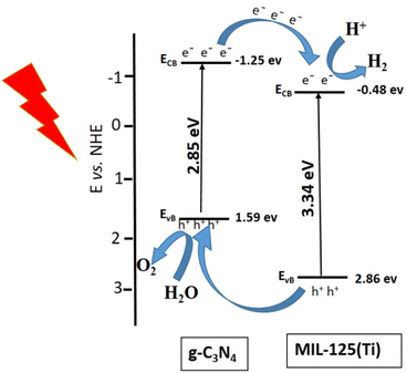 |
| | Fig. 8 Proposed mechanism for HER and OER under visible light illumination. | |
The conduction band (CB) and valence band (VB) of semiconductor are calculated by using following equations.
| | |
EVB = X − Ee + 0.5 Eg
| (4) |
Here,
X = absolute electronegativity of g-C
3N
4 (4.67 eV) and MIL-125(Ti) (5.69 eV),
Ee = energy of free electron on hydrogen scale (4.5 eV). The calculated
ECB and
EVB of g-C
3N
4 are −1.25 and 1.59 eV, respectively. While, for MIL-125(Ti), the calculated
ECB and
EVB are −0.48 eVand 2.86 eV, respectively. This band alignment suggests the development of type-II heterojunction at interface between g-C
3N
4 and MIL-125(Ti), represented by
Fig. 8. The pure g-C
3N
4 can be used for the generation of H
2 but the yield will be very less because the conduction band of g-C
3N
4 (−1.25 eV) is away from redox potential of H
+/H
2 (0.0 V
vs. NHE).
61 Under visible light illumination, electron from valence band of g-C
3N
4 is excited to conduction band. The conduction band of g-C
3N
4 is much negative than the CB of MIL-125(Ti) so electrons easily move from CB of g-C
3N
4 to CB of MIL-125(Ti). This electronic transfer occurs
via heterojunctional structure between g-C
3N
4 and titanium-oxo metallic cluster of MIL-125(Ti)
via, resulting in the reduction of H
2O into H
2 at the CB of MIL-125(Ti).
60 On the other hand, the holes (h
+) left in valence band of g-C
3N
4. The valence band of g-C
3N
4 (1.59 eV) is more positive than the redox potential of O
2/H
2O is 1.23 V
vs. NHE. So the holes in the balance band of g-C
3N
4 are used for oxidation of water into oxygen gas. Thus, heterojunction development between g-C
3N
4 and central metallic cluster of MIL-125(Ti) promoted the charge separation, increased the absorption of visible light and enhanced the photocatalytic activity.
Conclusions
In this work, MIL-125(Ti) and UiO-66 frameworks and their Heterojunctions g-C3N4@MIL-125(Ti) and g-C3N4@UiO-66 have been synthesized via in situ incorporation of g-C3N4 using one-step solvothermal method. The synthesis of samples was confirmed by PXRD, FTIR, SEM and ED-XRF analysis. It has been observed that incorporation of g-C3N4 does not disturb the crystal structure of MIL-125(Ti) and UiO-66. This indicates that this method is useful for incorporation of nanoparticles into MOFs and it maintains its integrity which has increased the charge separation and absorption of visible light. Hydrogen evolution reaction and oxygen evolution reactions are studied by cyclic voltammetry and linear sweep voltammetry. Among the synthesized heterojunctions, the g-C3N4@MIL-125(Ti) heterojunction delivered 10 mA cm−2 current density at just 86 mV and 173 mV overpotential for HER and OER respectively with significant stability up to 1000 s at 1.5 V applied potential under visible light exposure. This implies that the current strategy of incorporation of nanoparticles into MOFs is highly fertile for the enhancement of electrocatalytic activity of MOFs towards water splitting.
Author contributions
All the authors contributed equally to the article.
Conflicts of interest
There are no conflicts of interests to declare.
References
- P. Babar, A. Lokhande, H. H. Shin, B. Pawar, M. G. Gang, S. Pawar and J. H. Kim, Small, 2018, 14, 1702568 CrossRef PubMed
 .
. - S. M. Alshehri, A. N. Alhabarah, J. Ahmed, M. Naushad and T. Ahamad, J. Colloid Interface Sci., 2018, 514, 1–9 CrossRef CAS PubMed
 .
. - C. C. L. McCrory, S. Jung, J. C. Peters and T. F. Jaramillo, J. Am. Chem. Soc., 2013, 135, 16977–16987 CrossRef CAS PubMed
 .
. - Y. Cheng and S. P. Jiang, Prog. Nat. Sci.: Mater. Int., 2015, 25, 545–553 CrossRef CAS
 .
. - L. Zhang, J. Xiao, H. Wang and M. Shao, ACS Catal., 2017, 7, 7855–7865 CrossRef CAS
 .
. - B. Z. Desalegn, H. S. Jadhav and J. G. Seo, ChemCatChem, 2019, 11, 2870–2878 CrossRef CAS
 .
. - M. E. G. Lyons and S. Floquet, Phys. Chem. Chem. Phys., 2011, 13, 5314–5335 RSC
 .
. - O. Kasian, S. Geiger, P. Stock, G. Polymeros, B. Breitbach, A. Savan, A. Ludwig, S. Cherevko and K. J. J. Mayrhofer, J. Electrochem. Soc., 2016, 163, F3099–F3104 CrossRef CAS
 .
. - T. Y. Ma, J. Ran, S. Dai, M. Jaroniec and S. Z. Qiao, Angew. Chem., 2015, 127, 4729–4733 CrossRef
 .
. - M. G. Walter, E. L. Warren, J. R. McKone, S. W. Boettcher, Q. Mi, E. A. Santori and N. S. Lewis, Chem. Rev., 2010, 110, 6446–6473 CrossRef CAS PubMed
 .
. - J. Liang, X. Du, C. Gibson, X. W. Du and S. Z. Qiao, Adv. Mater., 2013, 25, 6226–6231 CrossRef CAS PubMed
 .
. - J. Masa, W. Xia, M. Muhler and W. Schuhmann, Angew. Chem., Int. Ed., 2015, 54, 10102–10120 CrossRef CAS PubMed
 .
. - Z. Xiang, D. Cao, L. Huang, J. Shui, M. Wang and L. Dai, Adv. Mater., 2014, 26, 3315–3320 CrossRef CAS PubMed
 .
. - Y. Zhu, B. Zhang, X. Liu, D. W. Wang and D. S. Su, Angew. Chem., 2014, 126, 10849–10853 CrossRef
 .
. - W. Gu, L. Hu, J. Li and E. Wang, ACS Appl. Mater. Interfaces, 2016, 8, 35281–35288 CrossRef CAS PubMed
 .
. - A. R. Millward and O. M. Yaghi, J. Am. Chem. Soc., 2005, 127, 17998–17999 CrossRef CAS PubMed
 .
. - A. Crake, K. C. Christoforidis, A. Kafizas, S. Zafeiratos and C. Petit, Appl. Catal., B, 2017, 210, 131–140 CrossRef CAS
 .
. - Y. Fang, Y. Ma, M. Zheng, P. Yang, A. M. Asiri and X. Wang, Coord. Chem. Rev., 2018, 373, 83–115 CrossRef CAS
 .
. - Y. Fu, X. Zhu, L. Huang, X. Zhang, F. Zhang and W. Zhu, Appl. Catal., B, 2018, 239, 46–51 CrossRef CAS
 .
. - X. Han, X. Yang, G. Liu, Z. Li and L. Shao, Chem. Eng. Res. Des., 2019, 143, 90–99 CrossRef CAS
 .
. - J. Feng, X. Yang, R. Li, X. Yang, H. Xu and X. Xi, Mater. Res. Express, 2019, 6, 045514 CrossRef
 .
. - S. Hu, R. Jin, G. Lu, D. Liu and J. Gui, RSC Adv., 2014, 4, 24863–24869 RSC
 .
. - Y. Liu, Y.-X. Yu and W.-D. Zhang, Int. J. Hydrogen Energy, 2014, 39, 9105–9113 CrossRef CAS
 .
. - Y. Li, X. Li, H. Zhang and Q. Xiang, Nanoscale Horiz., 2020, 5, 765–786 RSC
 .
. - Y. Li, X. Li, H. Zhang, J. Fan and Q. Xiang, J. Mater. Sci. Technol., 2020, 56, 69–88 CrossRef
 .
. - Z. L. Fang, H. F. Rong, Z. L. Ya and P. Qi, J. Mater. Sci., 2015, 50, 3057–3064 CrossRef CAS
 .
. - G. Zhang, D. Huang, M. Cheng, L. Lei, S. Chen, R. Wang, W. Xue, Y. Liu, Y. Chen and Z. Li, J. Mater. Chem. A, 2020, 8, 17883–17906 RSC
 .
. - M. Fiaz, M. Kashif, S. Majeed, M. N. Ashiq, M. A. Farid and M. Athar, ChemistrySelect, 2019, 4, 6996–7002 CrossRef CAS
 .
. - M. Fiaz, M. Athar, S. Rani, M. Najam-ul-Haq and M. A. Farid, Mater. Chem. Phys., 2020, 239, 122320 CrossRef CAS
 .
. - Z. Xue, X. Zhang, J. Qin and R. Liu, Appl. Surf. Sci., 2020, 510, 145489 CrossRef CAS
 .
. - A. Verma, D. P. Jaihindh and Y.-P. Fu, Dalton Trans., 2019, 48, 8594–8610 RSC
 .
. - J. Liu, T. Zhang, Z. Wang, G. Dawson and W. Chen, J. Mater. Chem., 2011, 21, 14398–14401 RSC
 .
. - S. Yu, R. D. Webster, Y. Zhou and X. Yan, Catal. Sci. Technol., 2017, 7, 2050–2056 RSC
 .
. - O. Alduhaish, M. Ubaidullah, A. M. Al-Enizi, N. Alhokbany, S. M. Alshehri and J. Ahmed, Sci. Rep., 2019, 9, 14139 CrossRef PubMed
 .
. - X.-H. Li, J. Zhang, X. Chen, A. Fischer, A. Thomas, M. Antonietti and X. Wang, Chem. Mater., 2011, 23, 4344–4348 CrossRef CAS
 .
. - Y. Zhao, W. Cai, J. Chen, Y. Miao and Y. Bu, Front. Chem., 2019, 7, 789 CrossRef CAS PubMed
 .
. - W. Zhang, H. Huang, F. Li, K. Deng and X. Wang, J. Mater. Chem. A, 2014, 2, 19084–19094 RSC
 .
. - S. Zhang, K. Chen, W. Peng and J. Huang, New J. Chem., 2020, 44, 3052–3061 RSC
 .
. - M. Shalom, S. Gimenez, F. Schipper, I. Herraiz-Cardona, J. Bisquert and M. Antonietti, Angew. Chem., 2014, 126, 3728–3732 CrossRef
 .
. - B. Zhang, H.-H. Wang, H. Su, L.-B. Lv, T.-J. Zhao, J.-M. Ge, X. Wei, K.-X. Wang, X.-H. Li and J.-S. Chen, Nano Res., 2016, 9, 2606–2615 CrossRef CAS
 .
. - M. Arif, G. Yasin, M. Shakeel, X. Fang, R. Gao, S. Ji and D. Yan, Chem. – Asian J., 2018, 13, 1045–1052 CrossRef CAS PubMed
 .
. - A. M. Paul, A. Sajeev, R. Nivetha, K. Gothandapani, P. Bhardwaj, G. K. V. Raghavan, G. Jacob, R. Sellapan, S. K. Jeong and A. N. Grace, Diamond Relat. Mater., 2020, 107, 107899 CrossRef CAS
 .
. - Z. Peng, S. Yang, D. Jia, P. Da, P. He, A. M. Al-Enizi, G. Ding, X. Xie and G. Zheng, J. Mater. Chem. A, 2016, 4, 12878–12883 RSC
 .
. - N.-n. Yang, Z.-g. Chen, Z.-g. Zhao and Y. Cui, New Carbon Mater., 2022, 37, 392–399 CrossRef
 .
. - Y. Zhao, F. Zhao, X. Wang, C. Xu, Z. Zhang, G. Shi and L. Qu, Angew. Chem., Int. Ed., 2014, 53, 13934–13939 CrossRef CAS PubMed
 .
. - Z. Pei, J. Zhao, Y. Huang, Y. Huang, M. Zhu, Z. Wang, Z. Chen and C. Zhi, J. Mater. Chem. A, 2016, 4, 12205–12211 RSC
 .
. - M. Zulqarnain, A. Shah, M. A. Khan, F. Jan Iftikhar and J. Nisar, Sci. Rep., 2020, 10, 6328 CrossRef CAS PubMed
 .
. - M. Ali and E. Pervaiz, Mol. Catal., 2022, 519, 112136 CrossRef CAS
 .
. - J. Yang, F. Zhang, X. Wang, D. He, G. Wu, Q. Yang, X. Hong, Y. Wu and Y. Li, Angew. Chem., Int. Ed., 2016, 55, 12854–12858 CrossRef CAS PubMed
 .
. - M. Fiaz and M. Athar, Catal. Lett., 2020, 150, 3314–3326 CrossRef CAS
 .
. - D. Tantraviwat, S. Anuchai, K. Ounnunkad, S. Saipanya, N. Aroonyadet, G. Rujijanagul and B. Inceesungvorn, J. Mater. Sci.: Mater. Electron., 2018, 29, 13103–13111 CrossRef CAS
 .
. - V. K. V. P. Srirapu, A. Kumar, P. Srivastava, R. N. Singh and A. S. K. Sinha, Electrochim. Acta, 2016, 209, 75–84 CrossRef CAS
 .
. - G. Karkera, T. Sarkar, M. D. Bharadwaj and A. S. Prakash, ChemCatChem, 2017, 9, 3681–3690 CrossRef CAS
 .
. - L. Bai, X. Wen and J. Guan, Mater. Today Energy, 2019, 12, 311–317 CrossRef
 .
. - L. Fan, P. Zhang, B. Zhang, Q. Daniel, B. J. J. Timmer, F. Zhang and L. Sun, ACS Energy Lett., 2018, 3, 2865–2874 CrossRef CAS
 .
. - C. Mahala and M. Basu, ACS Omega, 2017, 2, 7559–7567 CrossRef CAS PubMed
 .
. - J. Li, J. Song, B.-Y. Huang, G. Liang, W. Liang, G. Huang, Y. Qi Jin, H. Zhang, F. Xie, J. Chen, N. Wang, Y. Jin, X.-B. Li and H. Meng, J. Catal., 2020, 389, 375–381 CrossRef CAS
 .
. - M. Athar, M. Fiaz, M. A. Farid, M. Tahir, M. A. Asghar, S. ul Hassan and M. Hasan, ACS Omega, 2021, 6, 7334–7341 CrossRef CAS PubMed
 .
. - V. Charles, Y. Yang, M. Yuan, J. Zhang, Y. Li, J. Zhang, T. Zhao, Z. Liu, B. Li and G. Zhang, New J. Chem., 2021, 45, 14822–14830 RSC
 .
. - W. Wang, X. Xu, W. Zhou and Z. Shao, Adv. Sci., 2017, 4, 1600371 CrossRef PubMed
 .
. - J. Wen, J. Xie, X. Chen and X. Lia, Appl. Surf. Sci., 2017, 391, 72–123 CrossRef CAS
 .
.
|
| This journal is © The Royal Society of Chemistry 2022 |
Click here to see how this site uses Cookies. View our privacy policy here.  Open Access Article
 b,
Muhammad Kashifa,
Muhammad Asim Farid
 c,
Nagina Naveed Riazc and
Muhammad Athar*a


![[double bond, length as m-dash]](https://www.rsc.org/images/entities/char_e001.gif) C, C–H vibrations of benzene ring of organic ligand. However, it is observed that in both FTIR and Raman spectra of g-C3N4@MIL-125(Ti) and g-C3N4@UiO-66, vibrational peaks of g-C3N4 are not observed which indicates that the host MOFs dominate the g-C3N4 and both of them are close to each other due to physical and electrostatic interactions.
C, C–H vibrations of benzene ring of organic ligand. However, it is observed that in both FTIR and Raman spectra of g-C3N4@MIL-125(Ti) and g-C3N4@UiO-66, vibrational peaks of g-C3N4 are not observed which indicates that the host MOFs dominate the g-C3N4 and both of them are close to each other due to physical and electrostatic interactions.


.
.
.
.
.
.
.
.
.
.
.
.
.
.
.
.
.
.
.
.
.
.
.
.
.
.
.
.
.
.
.
.
.
.
.
.
.
.
.
.
.
.
.
.
.
.
.
.
.
.
.
.
.
.
.
.
.
.
.
.
.


