DOI:
10.1039/D2RA04939B
(Paper)
RSC Adv., 2022,
12, 29177-29186
Ni-MOF composite polypyrrole applied to supercapacitor energy storage
Received
7th August 2022
, Accepted 30th September 2022
First published on 12th October 2022
Abstract
Electrodes for supercapacitors made from metal–organic frameworks (MOFs) are still hindered by electron transfer properties. Therefore, an electrode composite material Ni-MOF@PPy was synthesized from a Ni-based metal–organic framework (Ni-MOF) doped with poly-pyrrole (PPy) using a simple chemical oxidation method to improve its electron transfer property. After introducing the electrochemically active substance K4Fe(CN)6 into the electrolyte, the composite material had a specific capacitance of 1815.4 F g−1 at a current density of 1 A g−1. Ni-MOF@PPy and active carbon (AC) as the positive and negative electrodes have been used, respectively, to assemble asymmetric supercapacitors (ASCs) in the KOH and K4Fe(CN)6 mixed electrolyte. This novel Ni-MOF@PPy//AC ASC energy storage device can provide 38.5 W h kg−1 energy density, 7001 W kg−1 power density, and 90.2% capacitance retention after 3000 cycles. Therefore, Ni-MOF@PPy//AC ASC is an excellent energy storage device with practical and economic value. The synergistic effect strategy proposed in this work can be easily applied to develop other MOFs with unique crystal structures as well as other redox active additives, providing new avenues and research ideas for exploring novel energy storage devices.
1. Introduction
Sustainable energy storage equipment supercapacitors (SCs), as the main energy modes of global energy use, are characterized by high power density and long cycle life but still have the disadvantage of low energy density.1 The key to constructing SCs with high energy density lies in enhancing their capacitance and broadening their potential.2 Metal–organic skeleton (MOF) materials are characterized by large pore volume, high specific surface area, and abundant active metal centers,3 which show excellent capacitive performance when applied to the SC electrode materials but are hindered by electrical conductivity. Composite materials can be used to increase MOF conductivity.4 Polypyrrole (PPy) is a common conductive polymer with the advantages of high conductivity, low cost, wide working potential window, and environmental friendliness.5 Compounding MOF materials with PPy can produce synergistic effects and overcome the electrochemical performance defects of a single component. Related studies6–8 have shown that PPy provides favorable charge transport channels and interlayer spacing of nanomaterials to facilitate ion diffusion kinetics and enhance material conductivity. For example, Chen et al.6 utilized the synergistic effect with abundant active sites and excellent electron transfer properties between the MOF material and PPy, and the Co–Ni(Fe)–MOF/PPy composite nanosheet-modified electrode realized a low detection limit and high sensitivity to detect glucose. Jiao et al.7 demonstrated that the conductive polymer chains of PPy not only increase the interlayer spacing of Zn/Ni-MOF but also provide a favorable charge transport channel, resulting in the excellent electrochemical performance of Zn/Ni-MOF@PPy, and a “trade-off effect” between the ion diffusion kinetics and conductivity was found under loaded PPy. Ma et al.8 utilized a conductive polymer-filled metal–organic framework (MOF) as the lithium host, in which polypyrrole (PPy) served as the “chain” to interlink Li “blocks” stored in the MOF pores, leading to low-barrier and dendrite-free Li plating/stripping with superb coulombic efficiency.
The potential window is also an important indicator-affecting energy density, and the potential window of the water-electrolyte is low. Adding electrochemically active substances in the electrolyte can not only improve the potential window but also provide additional pseudocapacitance.9 In many fields, including photoelectric chemistry and medicine, Fe(CN)64−/Fe(CN)63− have been used for their electrochemical reversibility.10,11 Due to its rapidly faradaic redox reaction, Fe(CN)64−/Fe(CN)63− redox couple can promote the charge transport of the electrolyte to improve the electrochemical performance of the capacitor.12–14 For example, Jain et al.12 fabricated the supercapacitor cell using CH3COONa with a specific capacitance and energy of 92 F g−1 and 7.1 W h kg−1, respectively, while adding K4Fe(CN)6 to CH3COONa, a change in capacitance (197 F g−1) and energy (18.2 W h kg−1) was observed, which is associated with the faradaic redox reaction between Fe(CN)64−/Fe(CN)63− redox couple. Ye et al.13 reported that the performance of CoTe//AC ASC could be improved by introducing the redox additive K4Fe(CN)6 into the KOH electrolyte, which exhibited nearly a threefold increase over the ASC with pristine electrolyte, achieving an ultrahigh specific capacitance of 192.1 F g−1 and energy density of 67.0 W h kg−1. An all-solid-state supercapacitor device composed of redox-active PVA–K3Fe(CN)6–K4Fe(CN)6 gel electrolyte and carbon nanotube paper electrodes was assembled by Kundu et al.,14 revealed that three-electrode tests using the aqueous K3Fe(CN)6–K4Fe(CN)6 electrolyte showed a specific capacitance 5 times larger than that of conventional aqueous H3PO4 electrolyte due to pseudocapacitive contribution of the redox ions. However, up to now, few studies on the effect of redox additives on the performance of MOF composite capacitors have been reported.
In this work, the electrode material Ni-MOF@PPy composed of Ni-MOF and PPy was synthesized by polymerization of pyrrole (Py) monomer by chemical oxidation method, and the electrochemically active substance Fe(CN)64−/Fe(CN)63− was introduced into the electrolyte. A novel Ni-MOF@PPy//AC asymmetric supercapacitor energy storage device was constructed based on the synergistic effect between the Ni-MOF@PPy composite material and Fe(CN)64−/Fe(CN)63− since they provided a charge transport channel and faradaic redox reaction, which showed a high energy density and long cycle life. This work not only provides a key idea for preparing MOF@(conductive polymer materials) with high performance but also provides a further understanding of the synergies between the components of MOF, conductive polymer, and redox additive.
2. Materials and methods
2.1 Chemical reagents
Some materials such as Ni(NO3)2·6H2O, K4Fe(CN)6·3H2O, triethylamine (TEA), N-methyl pyrrolidone (NMP), N,N-dimethylformamide (DMF) with 99% purity were purchased from China National Medicines Co. Ltd. (Beijing, China). Pyrrole (Py), 1,4-benzenedicarboxylic acid (PTA), polyvinylidene fluoride (PVDF), and Super-P were purchased from Aladdin Chemicals in Shanghai, China.
2.2 Preparation of Ni-MOF
A typical synthetic procedure for Ni-MOF involved direct mixing of TEA,15 as follows: the solution was composed of 2 mL of ethanol, 2 mL of H2O, and 30 mL of DMF, containing 0.75 mmol of NiCl2·6H2O and 0.75 of mmol PTA. After mixing this solution, 0.8 mL of TEA was added quickly and stirred for 5 min. The colloidal suspensions were then separately sonicated for 2 h at room temperature. Ni-MOF material was obtained by centrifugation, ethanol washing, and vacuum drying at 80 °C for 12 h.
2.3 Preparation of Ni-MOF@PPy
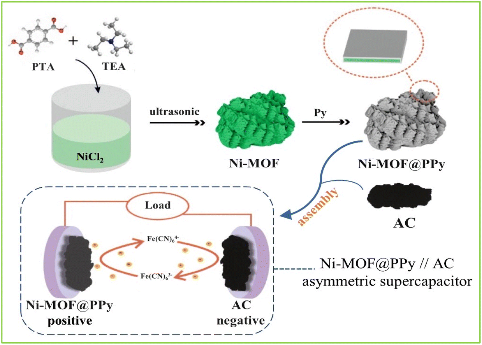
0.1 mL of Py monomer and 0.05 g of Ni-MOF were added dropwise to 10 mL of a mixed solution of ethanol and water (volume ratio 1![[thin space (1/6-em)]](https://www.rsc.org/images/entities/char_2009.gif) :1) and then stirred for 10 min. Then, under an ice-water bath, 2 mL of 0.16 g mL−1 ammonium persulfate solution was added dropwise, and the reaction was stirred for 2 h. The obtained product was washed with ethanol after centrifugation and dried at 60 °C for 12 h. The synthesis process is shown in Fig. 1. A series of Ni-MOF@PPy composites were synthesized with different quantities of PPy and abbreviated to PPy-MOF-X (“X” stands for volume of Py monomer (mL): 0.05, 0.1, 0.15).
:1) and then stirred for 10 min. Then, under an ice-water bath, 2 mL of 0.16 g mL−1 ammonium persulfate solution was added dropwise, and the reaction was stirred for 2 h. The obtained product was washed with ethanol after centrifugation and dried at 60 °C for 12 h. The synthesis process is shown in Fig. 1. A series of Ni-MOF@PPy composites were synthesized with different quantities of PPy and abbreviated to PPy-MOF-X (“X” stands for volume of Py monomer (mL): 0.05, 0.1, 0.15).
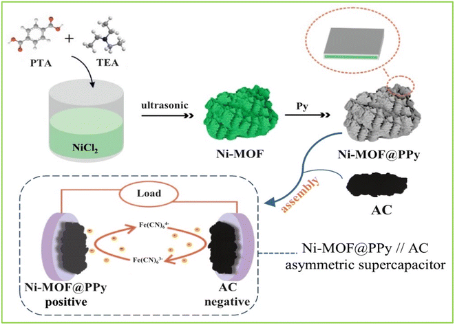 |
| | Fig. 1 The synthesis of Ni-MOF@PPy and its use in assembling Ni-MOF@PPy//AC asymmetric supercapacitor. | |
2.4 Material characterization
A scanning range of 5–50° was used to determine the crystal structure using an X-ray diffractometer (XRD, XRD-6000 Shimadzu Corporation, Japan). The molecular structure and functional groups were studied using the Fourier transform infrared (FTIR, MagnaIR550II, Nicolet) in the frequency range of 400–4000 cm−1. The micromorphology and microstructure of the samples were observed by scanning electron microscopy (SEM, JSM-7200 F, JEOL Ltd), the instrument was operated at 3.0 kV and EDS was used to analyze the element distribution of the MOF composites. Raman spectroscopy (Alpha 300R, WI Tec) at a wavelength of 488 nm was used for the detection of molecular structure and sample composition. The elemental composition of the materials was determined by X-ray photoelectron spectroscopy (XPS, CALAB Xi+, Thermo Fischer). Al Kα ray (hν = 1486.6 eV) was used as the excitation source, and the test was carried out under the condition of 12.5 kV working voltage and 16 mA filament current.
2.5 Preparation of Ni-MOF@PPy electrode and assembly of supercapacitor
To fabricate the electrode, 1.5 mg of an active substance containing 70 wt% Ni-MOF, 20 wt% black carbons (super P), and 10 wt% PVDF (60 wt%) were pressed onto a nickel foam (1 × 1 cm2). A Ni-MOF@PPy//AC ASC device was assembled with Ni-MOF@PPy as the cathode material, AC as the anode material, and a mixed solution of 2 mol L−1 KOH and 0.1 mol L−1 K4Fe(CN)6 as the electrolyte. The electrochemical station CHI 660 E (Shanghai Chenhua Instrument, Inc., China) was used for the electrochemical measurement of the nickel-based MOF material. A device with three electrodes was used to study CV, GCD, and EIS, using a saturated calomel electrode (SCE) and Pt plates as references and countering electrodes, respectively. In addition, the electrochemical performance and practical application value of the material under the condition of two electrodes were also studied.
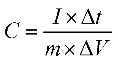
The specific capacitance C (F g−1) of electrode materials can be calculated as follows using eqn (1):
| |
 | (1) |
where Δ
V (V) is the window of the discharge, Δ
t (s) is the discharge time,
m (g) is the mass of the active material, and
I (A) is the current.
To obtain a charge balance, the best quality rate of the polarity should satisfy eqn (2).
| |
 | (2) |
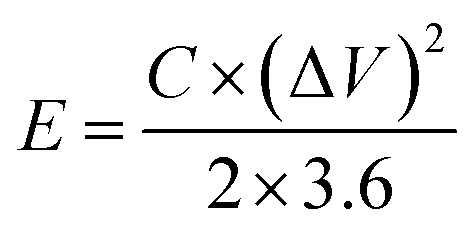
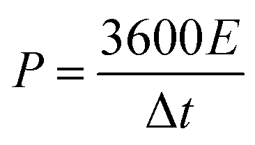
Eqn (3) and (4) can be used to calculate the energy density (E, W h kg−1) and power density (P, W kg−1) of the ASC device.
| |
 | (3) |
| |
 | (4) |
where Δ
V (V) is the potential range and Δ
t (s) is the total discharge time.
3. Results and discussion
3.1 Structure and morphological features
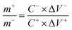
Ni-MOF@PPy composites were prepared by in situ polymerization of PPy on Ni-MOF by chemical oxidation polymerization. During the reaction process, the color of the sample can be observed to gradually change from light green (Ni-MOF) to black (Ni-MOF@PPy). According to Fig. 2a, Ni-MOF displays a diffraction peak similar to Ni-based MOF with C2/m spatial configuration (CCDC 985792), as reported previously.16,17 Ni-MOF@PPy showed the same XRD pattern as Ni-MOF, indicating that the structure of Ni-MOF is not destroyed during the polymerization of Py. Due to the amorphous nature of PPy, no obvious PPy diffraction peaks were observed in the PPy-MOF composites. In the magnified XRD image, it can be seen that the (200) characteristic diffraction peak of Ni-MOF@PPy shifts to a small angle. According to Bragg's law, the smaller the value of 2θ, the larger the layer spacing of the composite. This not only proves the formation of the composites but also reveals the incorporation of PPy into the interlayer of Ni-MOF. According to the XPS full spectrum (Fig. 2c), the composite contained Ni, C, N, and O elements. As shown in Fig. 2d, the backbone of the PPy chains is shown by the three peaks at 400.9 eV (–N+), 399.3 eV (–NH–), and 397.6 eV (–N![[double bond, length as m-dash]](https://www.rsc.org/images/entities/char_e001.gif) ) in the N 1s XPS spectra,18 which proved the successful preparation of PPy since PPy is the sole source of nitrogen. The XPS spectra of Ni 2p (Fig. 2e) show two fitted peaks of Ni 2p3/2 and Ni 2p1/2 positioned at about 856.0 eV and 873.6 eV, respectively, along with two significant satellite peaks (denoted as “Sat.”) at 861.8 eV and 880.2 eV, which are consistent with the reported peaks of Ni2+.19 XPS spectra of C 1s (Fig. 2f) can be fitted to four peaks positioned at about 284.4, 286.0, and 288.5 eV, assigned to CC/C–C, C–N, and CO components, respectively.20 The XPS spectra of O 1s (Fig. 2g) can be fitted to two peaks positioned at about 531.4 eV (CO) and 532.8 eV (C–OH/C–O–C), respectively.21 As shown in Fig. 2h, Raman peaks at 1356 cm−1 and 1580 cm−1 exhibit the structure of PPy, which corresponds to the stretching vibrations of C–N and CC bonds.22 The FTIR spectra of both Ni-MOF and Ni-MOF@PPy are similar (Fig. 2i). Ni-MOF@PPy exhibits stretching vibrational peaks for –COO–, –OH–, and –CH groups.23,24 Furthermore, there is a new characteristic absorption peak at 1211 cm−1, corresponding to the C–N stretching vibration in the pyrrole ring, which can prove the formation of PPy.25 The test results once again proved the existence of PPy in the composites.
) in the N 1s XPS spectra,18 which proved the successful preparation of PPy since PPy is the sole source of nitrogen. The XPS spectra of Ni 2p (Fig. 2e) show two fitted peaks of Ni 2p3/2 and Ni 2p1/2 positioned at about 856.0 eV and 873.6 eV, respectively, along with two significant satellite peaks (denoted as “Sat.”) at 861.8 eV and 880.2 eV, which are consistent with the reported peaks of Ni2+.19 XPS spectra of C 1s (Fig. 2f) can be fitted to four peaks positioned at about 284.4, 286.0, and 288.5 eV, assigned to CC/C–C, C–N, and CO components, respectively.20 The XPS spectra of O 1s (Fig. 2g) can be fitted to two peaks positioned at about 531.4 eV (CO) and 532.8 eV (C–OH/C–O–C), respectively.21 As shown in Fig. 2h, Raman peaks at 1356 cm−1 and 1580 cm−1 exhibit the structure of PPy, which corresponds to the stretching vibrations of C–N and CC bonds.22 The FTIR spectra of both Ni-MOF and Ni-MOF@PPy are similar (Fig. 2i). Ni-MOF@PPy exhibits stretching vibrational peaks for –COO–, –OH–, and –CH groups.23,24 Furthermore, there is a new characteristic absorption peak at 1211 cm−1, corresponding to the C–N stretching vibration in the pyrrole ring, which can prove the formation of PPy.25 The test results once again proved the existence of PPy in the composites.
 |
| | Fig. 2 Test and characterization spectrograms associated with Ni-MOF and Ni-MOF@PPy: (a) XRD patterns; (b) full-scale XPS spectrum of Ni-MOF@PPy, (c–g) fitted high-resolution XPS spectra of N 1s, Ni 1s, C 1s and O 1s of Ni-MOF@PPy; (h) Raman spectrum; (i) FTIR spectra. | |
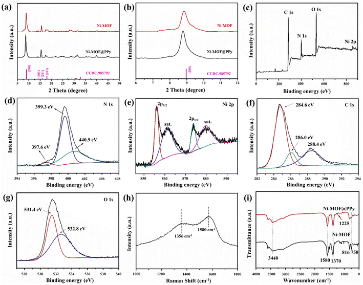
Fig. 3 shows the SEM images of Ni-MOF and Ni-MOF@PPy. Ni-MOF micro-blocks are sheet-like bulk structures formed by stacking. The open layered structures can provide storage space for electrolyte ions, which is beneficial for storing and migrating electrolyte ions.26 The as-synthesized Ni-MOF@PPy after PPy incorporation retained the original sheet structure, but the thickness of the nanosheets increased. The EDS energy-spectrum results of the composite material show that after the polymerization reaction, the product contains Ni, N, C, and O elements, which are very uniformly distributed on the surface of the micro-block. According to the results of SEM and EDS, combined with the above analysis of XRD, XPS, Raman, and FTIR, it can be inferred that PPy is successfully combined with Ni-MOF to form the Ni-MOF@PPy composite.
 |
| | Fig. 3 SEM images of (a and c) Ni-MOF and (b and d) Ni-MOF@PPy; (e–h) EDS element distribution images of (e) Ni, (f) N, (g) C, and (h) O for Ni-MOF@PPy. | |
3.2 Electrochemical measurements of Ni-MOF@PPy
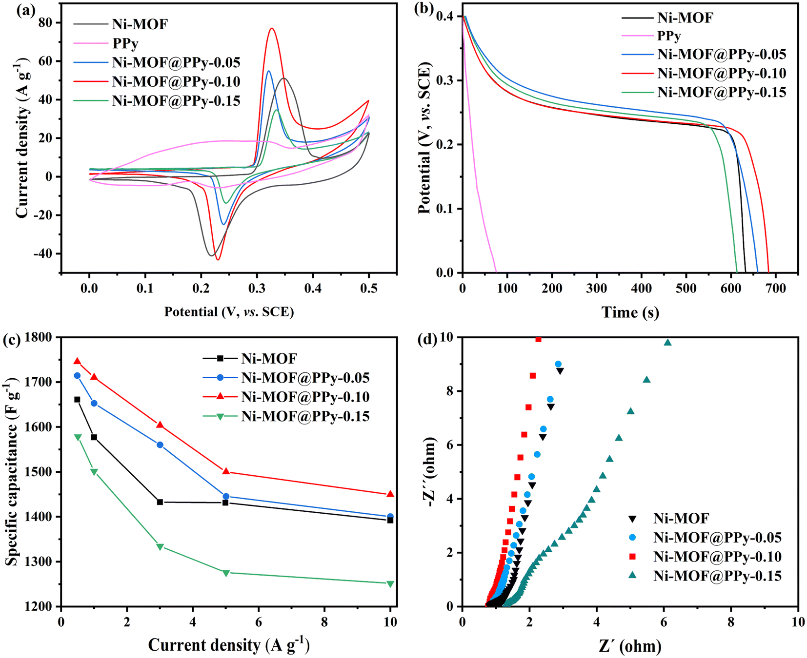
Ni-MOF@PPy was used as the working electrode in a three-electrode system in order to study its electrochemical energy storage behavior. As shown in Fig. 4a, CV curves for all composites showed redox peaks due to the surface faradaic redox reaction, corresponding to OH− reversible intercalation and deintercalation. This process can be described by eqn (5):27| | |
Ni2(OH)2(C8H4O4) + OH− + e− ⇌ Ni2O(OH)(C8H4O4) + H2O
| (5) |
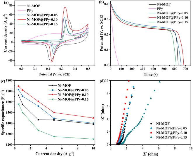 |
| | Fig. 4 The electrochemical performance test on four samples: (a) CV curves at 5 mV s−1; (b) GCD curves at 1 A g−1; (c) specific capacitance; (d) Nyquist plots. | |
From the voltammograms, at the same scan rate, the larger current response of the composite corresponds to a higher specific capacitance than that of pure Ni-MOF, which can be attributed to the faster electron transfer due to the combination of PPy and Ni-MOF. With an increase in Py addition, the CV curve area increases at first, then decreases. In Fig. 4b, the GCD curve for the composite at a current density of 1 A g−1 shows a typical steady state, indicating the electrode's Faraday redox reaction behavior. Obviously, the Ni-MOF@PPy-0.10 electrode has a longer discharge time than other electrodes. As shown in Fig. 4c, the specific capacitance can be calculated according to eqn (1). With a current density of 1 A g−1, Ni-MOF@PPy-0.10 (1710.0 F g−1) has a greater specific capacitance than Ni-MOF@PPy-0.05 (1625.4 F g−1), Ni-MOF@PPy-0.15 (1500.2 F g−1), Ni-MOF (1577.5 F g−1) and PPy (189.5 F g−1). According to the EIS curve (Fig. 4d) fitted by Zview software, Rct showed a downward trend with the increase of PPy, while Zw showed a trend of decreasing first and then increasing. The Rs (0.31 Ω) and Rct (0.59 Ω) values of the sample Ni-MOF@PPy-0.10 with 0.1 mL PPy are smaller than those of the other three samples. When the amount of PPy was less than 0.10 mL, the specific capacitance of the composites increased gradually with the increase in the amount of PPy. In this case, the Ni-MOF@PPy composite structure may provide a point-to-plane connected conductive network and accelerate ion-diffusion kinetics, leading to the increase of electron transfer between the electrolyte and active substance.28,29 However, when the addition amount of PPy is greater than 0.10 mL, the amount of synthesized PPy is too high, thus hindering the transfer process of electrolyte ions to Ni-MOF.7 In this case, ion diffusion resistance becomes a key factor affecting the electrochemical performance of composites. Therefore, Ni-MOF@PPy composites have a “balance effect” between the electron transfer property and ion transport resistance, that is, the main factor affecting the electrochemical performance changes from electron transfer to ion transport resistance with the increasing PPy content.
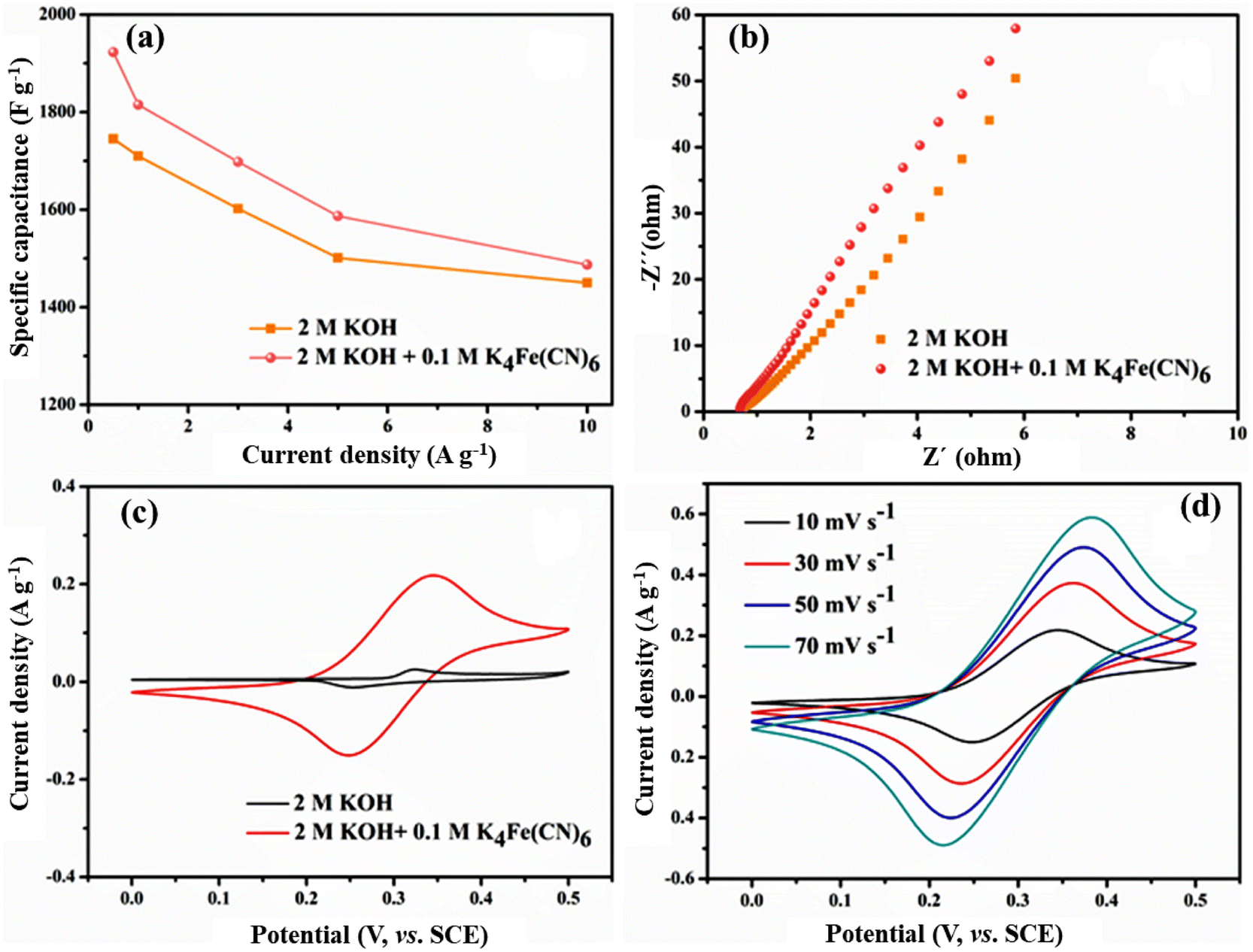
In order to further improve the electrochemical performance of the system, 0.1 M K4Fe(CN)6 was added to the original electrolyte, and the specific capacitance of the entire electrochemical system was increased by 5–10% (Fig. 5a). For example, in the mixed electrolyte at a current density of 1 A g−1, the specific capacitance of Ni-MOF@PPy reaches 1815.4 F g−1, which is 6.1% higher than that of the single electrolyte. The EIS curves of the Ni-MOF@PPy-0.1 electrode in the two electrolytes are shown in Fig. 5b. In the mixed electrolyte system, the charge transfer rate of the interface between electrode and electrolyte is higher due to lower Rs (0.22 Ω) and Rct (0.51 Ω), and the dynamic characteristics are more obvious. Low-frequency impedance curve slopes in the mixed electrolyte liquid system are steeper, indicating a faster ion diffusion rate.30 In order to explore the role of K4Fe(CN)6 in the mixed electrolyte system, the nickel foam without any redox active additive was directly used as the working electrode, which was placed in the single and mixed electrolytes for CV tests. Fig. 5c shows the CV graphs of nickel foam in different electrolytes at a scanning rate of 10 mV s−1. CV curves of nickel foam electrodes in mixed electrolytes have a much larger area than those in single electrolytes, and almost resemble a straight line in 2 M KOH, indicating that its contribution to the capacity of the entire system is almost negligible. The electrode material has better capacitance and charge storage ability when it is in a mixed electrolyte system. It can be seen from Fig. 5d that symmetrical redox peaks can be clearly observed on CV curves at different scanning rates, which can be attributed to the occurrence of the following reversible redox reactions:31
| | |
Fe(CN)64− − e− ⇌ Fe(CN)63−
| (6) |
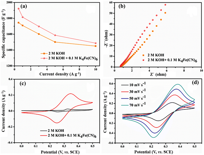 |
| | Fig. 5 (a) Specific capacitances and (b) Nyquist plots of Ni-MOF@PPy-0.10 in two electrolytes; (c) CV curves at a scanning rate of 10 mV s−1 in two electrolytes with foamed nickel as the working electrode; (d) CV curves at different scanning rates in the mixed electrolyte. | |
With the gradual increase in scanning rate, the oxidation peak and reduction peak still maintain good symmetry, proving that the electrochemical reaction process in the mixed electrolyte system is a rapid quasi-reversible redox reaction process.32 The results further indicate that the K4Fe(CN)6 electrolyte is a liquid electrolyte with high electrochemical activity and can contribute to pseudocapacitance independently. During the application of an electric field, K4Fe(CN)6 will move to the electrode surface and participates in the chemical reaction, forming a Fe(CN)64−/Fe(CN)63− redox electric pair. In the charging and discharging process, Fe(CN)63− and Fe(CN)64− can be used as the electron acceptor and electron donor, respectively. In the presence of Fe(CN)64−/Fe(CN)63− redox electric pair, diffusion resistance, and charge transfer resistance are reduced, while the chemical reaction rate improves. Therefore, the presence of the redox active additive K4Fe(CN)6 can not only provide additional pseudocapacitance for the whole system but also accelerate the electrochemical reaction process of the system and improve the electrochemical performance of the whole system.33
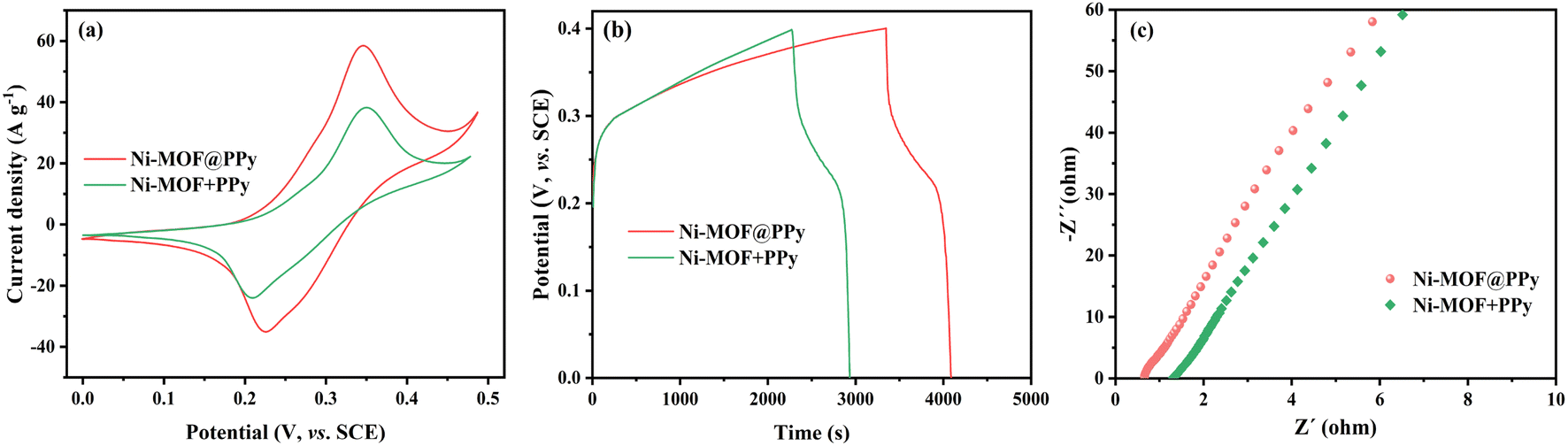
The electrochemical properties of Ni-MOF@PPy and Ni-MOF + PPy (a physical mixture of Ni-MOF and PPy) were compared. As shown in Fig. 6a, the region area of the CV curve of Ni-MOF@PPy electrode material is significantly larger than that of Ni-MOF + PPy, indicating that more electrochemical reactions occur at the Ni-MOF@PPy electrode. In Fig. 6b, the constant-current charge–discharge curves of the two electrode materials were compared. According to the discharge time, the specific capacitances of the two electrode materials were calculated to be 1815.4 and 1591.7 F g−1 respectively. As shown in Fig. 6c, in the high-frequency range, the intersection between the curve in the impedance spectrum and the X-axis represents the equivalent series resistance (Rs), which comes from the inherent internal resistance of the electrode material.34 The Rs resistance of Ni-MOF@PPy is obviously less than that of Ni-MOF + PPy. For Ni-MOF + PPy electrode materials, the contact type between Ni-MOF and PPy is “point contact” and PPy can only touch the outer surface of the blocky Ni-MOF. Comparison experiments further proved that the synthesized Ni-MOF@PPy composite is different from Ni-MOF + PPy, and PPy is speculated to extend into the structure of Ni-MOF, making PPy and Ni-MOF form a “face contact”.
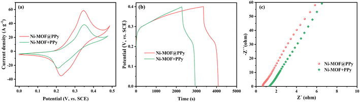 |
| | Fig. 6 The electrochemical performance measurements of Ni-MOF@PPy and Ni-MOF + PPy: (a) GCD curves at 1 A g−1; (b) CV curves at 5 mV s−1; (c) Nyquist plots. | |
CV tests at a low scanning rate (0.2–1 mV s−1) were performed on the material in the voltage range of 0–0.5 V to further understand reaction kinetics and charge storage mechanisms. The capacitive contribution can be quantified based on the equation: log(i) = blog(v) + log(a), wherein, i represent the peak current (A), v is the scan rate, and a and b are both variable parameters.35 The b value can be obtained from the slopes of log(i) and log(v) linear curves, reflecting the Ni2+ storage mechanism. Generally, b closing to 0.5 is a diffusion-controlled process, whereas b = 1 represents capacitive-dominant behavior.36 Diffusion-controlled control is beneficial for storing more charge, while the capacitive-dominant process is beneficial for fast charging and discharging.37 According to Fig. 7a, the b value at oxidation and reduction peak voltages are close to 1, indicating the pseudocapacitance properties of the electrode material. Fig. 7b shows the contribution from capacitance and diffusion. When the scanning rates were 0.2, 0.4, 0.6, 0.8 and 1 mV s−1, the capacitive-dominant contribution was 79.3%, 80.1%, 82.9%, 84.2% and 85.4%, respectively.
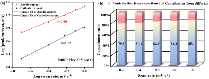 |
| | Fig. 7 (a) log(i) and log(v) plots at specific peak currents; (b) capacitive contribution histogram at different scanning rates. | |
3.3 Electrochemical performance in the two-electrode system
In order to evaluate the practical application of Ni-MOF@PPy, Ni-MOF@PPy//AC ASC was fabricated using Ni-MOF@PPy-0.10 composite as the positive electrode, AC as the negative electrode, and 2 M KOH + 0.1 M K4Fe(CN)6 (mixed electrolyte) as an electrolyte, respectively. When the current density of the three-electrode system is 1 A g−1, the specific capacitances of AC and Ni-MOF@PPy are 154.3 F g−1 and 1815.4 F g−1, respectively, and the potential windows of AC are −0.8–0 V and Ni-MOF@PPy 0–0.4 V, respectively. According to eqn (2), the Ni-MOF@PPy//AC ASC has an electrode active substance load of 10.5 mg cm−2 when its mass ratio is 1:6 between Ni-MOF@PPy and the AC electrode material, where Ni-MOF@PPy and AC have masses of 1.5 mg cm−2 and 9.0 mg cm−2, respectively. Ni-MOF@PPy//AC ASC energy storage mechanism is shown in Fig. 1. Hierarchically porous nanomaterials can enhance the electrochemically active surface area, which gives rise to quick electrolyte accessibility and a correspondingly immediate capacitive response in supercapacitor.38 For example, a unique layered structure of Ni-MOF can store a large number of electrolyte ions, and the huge specific surface area improves the effective utilization rate of the electrode materials. Meanwhile, the introduction of PPy can increase the conductivity, provide conductive channels for electron transmission, and improve the cycle life of energy storage devices with stable structures. The AC electrode material used for the negative electrode provides double-layer capacitance, providing long-term cycling stability. The electrochemical active substance K4Fe(CN)6 was introduced into the KOH electrolyte, and the synergistic effect of each component made Ni-MOF@PPy//AC ASC have a high energy density and power density at the same time.
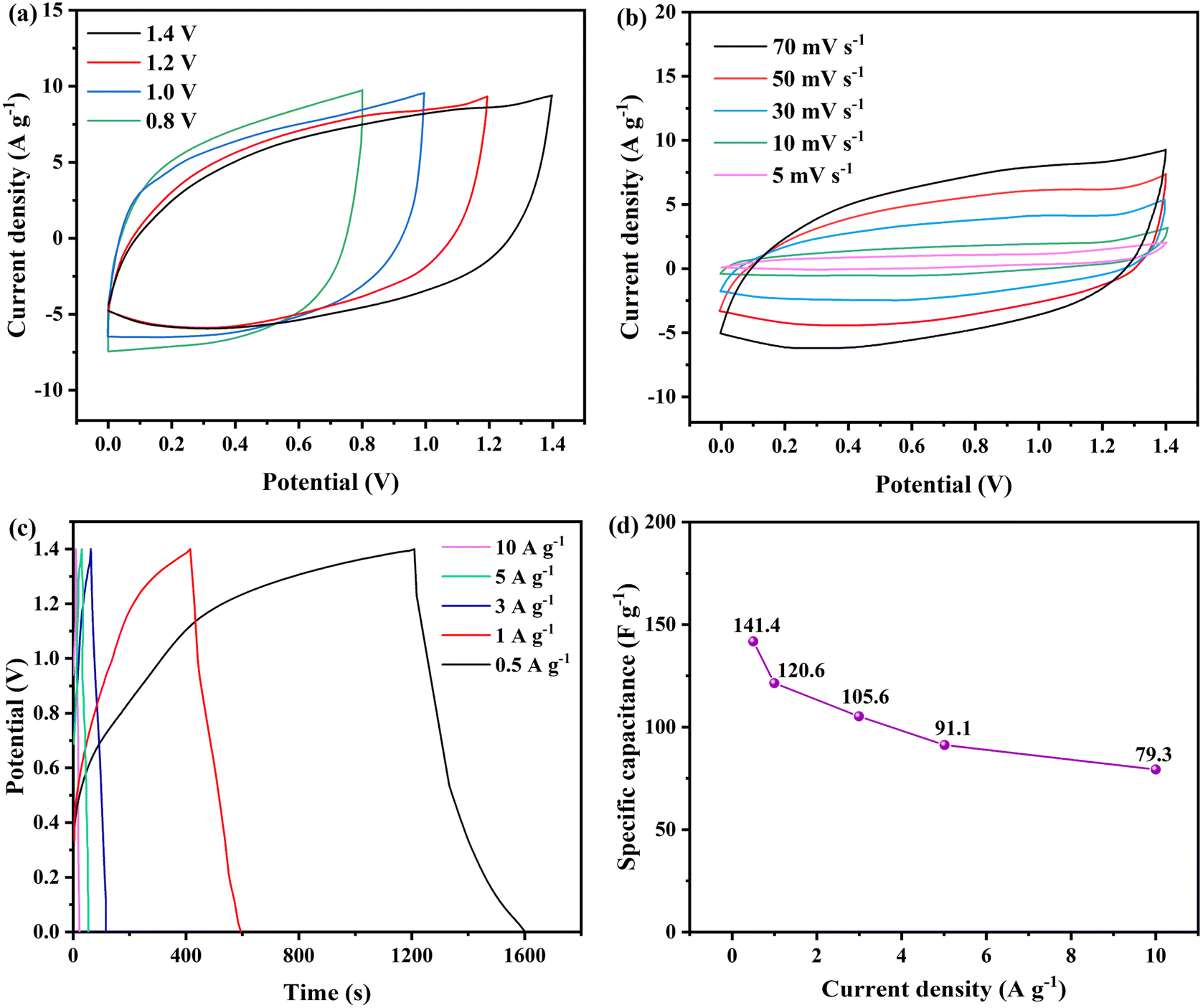
Firstly, CV tests were performed on Ni-MOF@PPy//AC ASC at different potential ranges (0–0.8, 0–1.0, 0–1.2, 0–1.4 V) and 70 mV s−1 scanning rate (Fig. 8a). When the voltage window was extended to 1.4 V, the CV curve of the supercapacitor showed double layer characteristics and Faraday redox behavior, and there was no obvious polarization phenomenon, indicating that the voltage window of the system is 1.4 V. CV curves at different scanning rates are displayed in Fig. 8b. At scanning rates up to 70 mV s−1, the shape of CV curves almost does not distort, which proves that the electrochemical reaction process of the energy storage device is highly reversible with small resistance.39 In the GCD test, the ASC device reached a high potential of 1.4 V, as shown in Fig. 8c and d. When the current density is 0.5, 1, 3, 5, and 10 A g−1, the specific capacitance of the ASC device is 141.4, 120.6, 105.6, 91.1 and 79.3 F g−1, respectively.
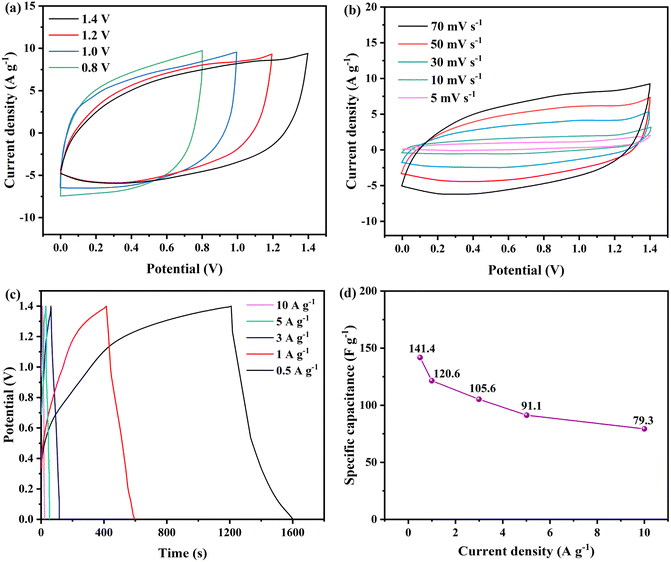 |
| | Fig. 8 The electrochemical performance of Ni-MOF@PPy//AC ASC: (a) CV curves at different voltage windows; (b) CV curves under different scanning rates; (c) GCD curves at different current densities; (d) specific capacitance curve at different current densities. | |
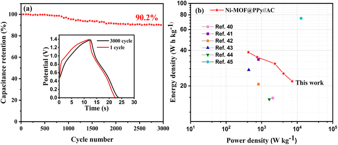
As shown in Fig. 9a, 3000 GCD tests were performed on Ni-MOF@PPy//AC ASC at a current density of 10 A g−1. According to the test results, the Ni-MOF@PPy//AC ASC retains 90.2% of its specific capacitance after 3000 cycles, indicating that it is a stable energy storage device. Based on the above test data and formulas (3) and (4), the Ragone diagram (Fig. 9b) of Ni-MOF@PPy//AC ASC was calculated. It can be seen that the energy density of Ni-MOF@PPy//AC ASC can reach 38.5 W h kg−1, which is better than the results of some literature studies reported thus far, as shown in Table 1. As a result of these studies, the developed electrode material Ni-MOF@PPy can be a great candidate for portable supercapacitors.
 |
| | Fig. 9 (a) Cycling stability at 10 A g−1 over 3000 cycles and (b) Ragone plots of the ASC device. | |
Table 1 Performance comparison of energy storage devices
| Working electrode |
Counter electrode |
Potential window (V) |
Electrolyte |
Energy density (W h kg−1) |
Power density (W kg−1) |
Sources |
| Ni-MOF |
AC |
0.4–1.6 |
2 M KOH |
16.5 |
2000 |
40 |
| Ni-MOF |
AC |
0–1.6 |
2 M KOH |
31.5 |
800 |
41 |
| Ni/Co-MOF |
AC |
0–1.6 |
2 M KOH |
20.9 |
800 |
42 |
| Co3O4@PPy |
Co3O4 |
0–1.4 |
1 M KOH |
26.3 |
350 |
43 |
| PPy/rGO |
NCs |
0–1.6 |
Polyvinyl alcohol/LiCl |
15.8 |
1640 |
44 |
| Carbon/Li3N |
AC |
2–4 |
1 M LiPF6 |
74.7 |
12900 |
45 |
| Ni-MOF@PPy |
AC |
0–1.4 |
2 M KOH + 0.1 M K4Fe(CN)6 |
38.5 |
7001 |
This study |
4. Conclusions
We successfully prepared Ni-MOF@PPy composites by the chemical oxidation method. Different composite amounts of PPy were used to control the balance between ion diffusion resistance and electron transfer property, and the optimized composites exhibited excellent capacitance. In addition, after adding K4Fe(CN)6 to the traditional electrolyte KOH, the specific capacitance of the whole system was increased by 6.1%. Based on the synergistic effect between Ni-MOF@PPy composite material and Fe6(CN)4−/Fe(CN)63− since they provided a charge transport channel and faradaic redox reaction, a novel Ni-MOF@PPy//AC asymmetric supercapacitor energy storage device was constructed, which can provide 38.5 W h kg−1 energy density, 7001 W kg−1 power density, and 90.2% capacitance retention after 3000 cycles. Therefore, Ni-MOF@PPy//AC asymmetric supercapacitor is a novel energy storage device with practical and economic value. The synergistic effect strategy proposed in this work can be easily applied to develop other MOFs with unique crystal structures as well as other redox active additives, providing new avenues and research ideas for exploring novel energy storage devices.
Author contributions
Zhao Qin: data curation, formal analysis, writing – original draft. Yanqin Xu: methodology, supervision, validation, visualization. Lin Liu: project administration, resources, software. Min Liu: data curation, formal analysis, validation. Hanjun Zou: project administration, resources, software. Liyue Xiao: project administration, supervision. Yuan Cao: funding acquisition, methodology, writing – review & editing. Changguo Chen: funding acquisition, writing – review & editing.
Conflicts of interest
There are no conflicts to declare.
Acknowledgements
This research was financially supported by the National Natural Science Foundation of China (21273292; 21676036).
References
- J. Liu, J. Wang, C. Xu, H. Jiang, C. Li, L. Zhang, J. Lin and Z. X. Shen, Adv. Sci., 2018, 5, 1700322 CrossRef.
- D.-G. Wang, Z. Liang, S. Gao, C. Qu and R. Zou, Coord. Chem. Rev., 2020, 404, 213093 CrossRef CAS.
- F. Yang, H. Sadam, Y. Zhang, J. Xia, X. Yang, J. Long, S. Li and L. Shao, Chem. Eng. Sci., 2020, 225, 115845 CrossRef CAS.
- J. Yang, P. Xiong, C. Zheng, H. Qiu and M. Wei, J. Mater. Chem. A, 2014, 2, 16640–16644 RSC.
- W. Li, W. Ding, G. Wu, J. Liao, N. Yao, X. Qi, L. Li, S. Chen and Z. Wei, Chem. Eng. Sci., 2015, 135, 45–51 CrossRef CAS.
- S. Chen, D. Liu, N. Song, C. Wang and X. Lu, Compos. Commun., 2022, 30, 101074 CrossRef.
- Y. Jiao, G. Chen, D. Chen, J. Pei and Y. Hu, J. Mater. Chem. A, 2017, 5, 23744–23752 RSC.
- Y. Ma, L. Wei, Y. He, X. Yuan, Y. Su, Y. Gu, X. Li, X. Zhao, Y. Qin, Q. Mu, Y. Peng, Y. Sun and Z. Deng, Angew. Chem., Int. Ed., 2022, 61, e202116291 CAS.
- L. Hu, T. Zhai, H. Li and Y. Wang, ChemSusChem, 2019, 12, 1118–1132 CrossRef CAS PubMed.
- W.-L. Wang, J. Zhang, Q.-S. Wang, L. Chen and Z.-P. Liu, J. Inorg. Mater., 2019, 34, 1301–1308 CrossRef.
- R. K. Ameta, R. R. Koshti, A. Vyas, C. Rane, N. K. Sharma and M. Singh, J. Mol. Liq., 2018, 268, 677–684 CrossRef CAS.
- D. Jain, J. Kanungo and S. K. Tripathi, J. Electrochem. Soc., 2019, 166, A3168–A3181 CrossRef.
- B. R. Ye, C. Gong, M. L. Huang, Y. G. Tu, X. Q. Zheng, L. Q. Fan, J. M. Lin and J. H. Wu, RSC Adv., 2018, 8, 7997–8006 RSC.
- A. Kundu and T. S. Fisher, ACS Appl. Energy Mater., 2018, 1, 5800–5809 CrossRef.
- J. Hu, Y. Chen, H. Zhang, Z. Chen, Y. Ling, Y. Yang, X. Liu, Y. Jia and Y. Zhou, Microporous Mesoporous Mater., 2021, 315, 110900 CrossRef.
- A. Mesbah, P. Rabu, R. Sibille, S. Lebegue, T. Mazet, B. Malaman and M. Francois, Inorg. Chem., 2014, 53, 872–881 CrossRef CAS PubMed.
- S. Zhao, Y. Wang, J. Dong, C.-T. He, H. Yin, P. An, K. Zhao, X. Zhang, C. Gao, L. Zhang, J. Lv, J. Wang, J. Zhang, A. M. Khattak, N. A. Khan, Z. Wei, J. Zhang, S. Liu, H. Zhao and Z. Tang, Nat. Energy, 2016, 1, 1–10 Search PubMed.
- D. Guo, M. Zhang, Z. Chen and X. Liu, Mater. Res. Bull., 2017, 96, 463–470 CrossRef CAS.
- J. Wang, Q. Zhong, Y. Zeng, D. Cheng, Y. Xiong and Y. Bu, J. Colloid Interface Sci., 2019, 555, 42–52 CrossRef CAS.
- W. Liu, K. Wang, C. Li, X. Zhang, X. Sun, J. Han, X.-L. Wu, F. Li and Y. Ma, J. Mater. Chem. A, 2018, 6, 24979–24987 RSC.
- Y. Wang, B. Chen, Y. Zhang, L. Fu, Y. Zhu, L. Zhang and Y. Wu, Electrochim. Acta, 2016, 213, 260–269 CrossRef CAS.
- B. Wang, X. He, H. Li, Q. Liu, J. Wang, L. Yu, H. Yan, Z. Li and P. Wang, J. Mater. Chem. A, 2014, 2, 12968–12973 RSC.
- A. D. Su, X. Zhang, A. Rinaldi, S. T. Nguyen, H. Liu, Z. Lei, L. Lu and H. M. Duong, Chem. Phys. Lett., 2013, 561, 68–73 CrossRef.
- Q. Li, C. Lu, C. Chen, L. Xie, Y. Liu, Y. Li, Q. Kong and H. Wang, Energy Storage Mater., 2017, 8, 59–67 CrossRef.
- B. Wang, W. Li, Z. Liu, Y. Duan, B. Zhao, Y. Wang and J. Liu, RSC Adv., 2020, 10, 12129–12134 RSC.
- Y. Zhou, Z. Mao, W. Wang, Z. Yang and X. Liu, ACS Appl. Mater. Interfaces, 2016, 8, 28904–28916 CrossRef CAS.
- J. Yang, C. Zheng, P. Xiong, Y. Li and M. Wei, J. Mater. Chem. A, 2014, 2, 19005–19010 RSC.
- L. Huang, X. Yao, L. Yuan, B. Yao, X. Gao, J. Wan, P. Zhou, M. Xu, J. Wu, H. Yu, Z. Hu, T. Li, Y. Li and J. Zhou, Energy Storage Mater., 2018, 12, 191–196 CrossRef.
- Z. Song, L. Miao, H. Duan, L. Ruhlmann, Y. Lv, D. Zhu, L. Li, L. Gan and M. Liu, Angew. Chem., Int. Ed., 2022, 61, e202208821 CAS.
- M. S. Rahmanifar, H. Hesari, A. Noori, M. Y. Masoomi, A. Morsali and M. F. Mousavi, Electrochim. Acta, 2018, 275, 76–86 CrossRef CAS.
- M. Zhou, J. Qian, X. Ai and H. Yang, Adv. Mater., 2011, 23, 4913–4917 CrossRef CAS.
- J. Hong, S.-J. Park and S. Kim, Electrochim. Acta, 2019, 311, 62–71 CrossRef CAS.
- F. de Lima and G. Maia, Nanoscale, 2015, 7, 6193–6207 RSC.
- Y. Chen, D. Ni, X. Yang, C. Liu, J. Yin and K. Cai, Electrochim. Acta, 2018, 278, 114–123 CrossRef CAS.
- W. Du, L. Miao, Z. Song, X. Zheng, Y. Lv, D. Zhu, L. Gan and M. Liu, J. Power Sources, 2022, 536, 231512 CrossRef CAS.
- Z. Song, H. Duan, L. Miao, L. Ruhlmann, Y. Lv, W. Xiong, D. Zhu, L. Li, L. Gan and M. Liu, Carbon, 2020, 168, 499–507 CrossRef CAS.
- Y. Xu, L. Liu, C. Xu, X. Wang, M. Y. Tan and Y. Huang, J. Solid State Electrochem., 2020, 24, 2511–2524 CrossRef CAS.
- Y. Qin, L. Miao, M. Mansuer, C. M. Hu, Y. K. Lv, L. H. Gan and M. X. Liu, ACS Appl. Mater. Interfaces, 2022, 14, 33328–33339 CrossRef PubMed.
- A. Melemed and B. Gallant, J. Electrochem. Soc., 2020, 167, 140543 CrossRef.
- L. Kang, S.-X. Sun, L.-B. Kong, J.-W. Lang and Y.-C. Luo, Chin. Chem. Lett., 2014, 25, 957–961 CrossRef.
- S. Gao, Y. Sui, F. Wei, J. Qi, Q. Meng and Y. He, J. Mater. Sci., 2018, 53, 6807–6818 CrossRef.
- S. Gao, Y. Sui, F. Wei, J. Qi, Q. Meng, Y. Ren and Y. He, J. Colloid Interface Sci., 2018, 531, 83–90 CrossRef.
- J. Xu, T. Xiao, X. Tan, P. Xiang, L. Jiang, D. Wu, J. Li and S. Wang, J. Alloys Compd., 2017, 706, 351–357 CrossRef.
- J. Zhu, T. Feng, X. Du, J. Wang, J. Hu and L. Wei, J. Power Sources, 2017, 346, 120–127 CrossRef.
- C. Sun, X. Zhang, C. Li, K. Wang, X. Sun and Y. Ma, Energy Storage Mater., 2020, 24, 160–166 CrossRef.
|
| This journal is © The Royal Society of Chemistry 2022 |
Click here to see how this site uses Cookies. View our privacy policy here. 
 Open Access Article
 This Open Access Article is licensed under a Creative Commons Attribution-Non Commercial 3.0 Unported Licence
 a,
Yanqin Xu
a,
Yanqin Xu