 Open Access Article
Mechanistic study of the bismuth mediated fluorination of arylboronic esters and further rational design†
Jiali Caia,
Minna Zhia,
Junyuan Hua,
Tingting Pua,
Kai Guo c and
Lili Zhao
 *ab
*ab
aInstitute of Advanced Synthesis, School of Chemistry and Molecular Engineering, Jiangsu National Synergetic Innovation Center for Advanced Materials, Nanjing Tech University, Nanjing 211816, China. E-mail: ias_llzhao@njtech.edu.cn
bCollege of Chemical Engineering, State Key Laboratory of Materials-Oriented Chemical Engineering, Nanjing Tech University, Nanjing 211816, China
cCollege of Biotechnology and Pharmaceutical Engineering, Nanjing Tech University, 30 Puzhu Rd S., Nanjing 211816, China
First published on 25th August 2022
Abstract
Density functional theory (DFT) calculations have been performed to gain insight into the catalytic mechanism of the bismuth redox catalyzed fluorination of arylboronic esters to deliver the widely used arylfluoride compounds (Science 2020, 367, 313–317). The study reveals that the whole catalysis can be characterized via three stages: (i) transmetallation generates the Bi(III) intermediate 5, capitalizing on the use of KF as an activator. (ii) 5 then reacts with the electrophilic fluorination reagent 1-fluoro-2,6-dichloropyridinium 4 via oxidative addition to give the Bi(V) intermediate IM4A. (iii) IM4A undergoes a reductive elimination step to yield aryl fluoride compounds and regenerates the bismuth catalyst for the next catalytic cycle. Each stage is kinetically and thermodynamically feasible. The transmetallation step, with a barrier of 25.4 kcal mol−1, is predicted to be the rate-determining step (RDS) during the whole catalytic cycle. Furthermore, based on a mechanistic study, new catalysts with the framework of tethered bis-anionic ligands were designed, which will help to improve current catalytic systems and develop new bismuth mediated fluorination of arylboronic esters.
Introduction
Fluorinated organic compounds have been considered as very important intermediates in modern pharmaceuticals,1,2 agrochemicals,3 materials4 and tracers for positron emission tomography (PET).5 However, only a small fraction of organic fluorides can be achieved by natural biosynthesis, which arises from the most electronegative and the least nucleophilic characters of fluorine and thus make the carbon–fluorine bond formation challenging.6–9 In the past decades, significant progress has been made in C(sp3)–F bond formation including the asymmetric α-fluorination of carbonyl compounds mediated by organo-10–12 and metal-catalysts.13,14 However, only few C(sp2)–F bond formation, especially aromatic carbon–fluorine bonds, have been reported. At present, the reported available methods for aryl C–F bond formation, include the Balz–Schiemann reaction,15 the Halex process,16,17 transition metal-catalyzed or mediated procedures,18,19 deoxyfluorination of phenols,20 and fluorination of aryl Grignard reagents.21 Unfortunately, these methods suffer from harsh reaction conditions or highly activated substrates. Therefore, it's anticipated to develop efficient and simple strategies, which allow the installation of stable, easily-handled and readily-introduced precursor functional groups into fluorine atoms. In this regard, boron-containing complexes perform well and become the promising precursors.Organoboron reagents, which are stable, normally non-toxic and excellent functional-group tolerant, can be widely used in C–C and C–B bond formation,22 as well as in the development of metal-catalyzed cross coupling reactions, such as Suzuki–Miyaura coupling and Chan–Lam coupling.23,24 However, organoboron reagents have rarely been reported as precursor for C–F bond formations. This situation is beginning to change with the development of modern metal-mediated fluorination processes. The transition metals (e.g., Pd,25 Ag,26 Cu27,28) have been used for aromatic carbon–fluorine bond formation, which used fluorinating agents that are more easily handled, including the electrophilic N–F reagents (e.g., Selectfluor and NFSI)27,29,30 Considering the transition metal catalysts are expensive and less abundant due to over-exploitation, the employment of much cheaper and abundant main-group elements in such transformation process is promising. In this respect, the bismuth (Bi) involving complexes have great potential in the field of sustainable catalysis due to the inexpensive and abundant properties of main group bismuth element.31 However, the employment of bismuth element in catalysis is mainly dependent on its soft Lewis acidity with a fixed oxidation state,32 rather than its redox capacities. Until so far, the exploitation of bismuth's redox capacities in catalysis, which can access transition-metal reactivity, is still challenging. In 2020, Cornella et al. rationally designed a series of bismuth complexes with the tethered bis-anionic aryl ligands, which can be used as active catalysts for the fluorination of aryl boronic esters through a Bi(III)/Bi(V) redox cycle under mild conditions (Scheme 1).33 The rigid skeleton of the tethered ligands can effectively avoid Berry pseudo-rotation or turnstile rotation of the highvalent bismuth intermediates, and the lone pair of the S-bound nitrogen would serve as a weak ligand for the Bi center, which helps to stabilize the geometries of the Bi(V) compounds during the catalytic cycle. Moreover, the efficiency with respect to the valuable aryl moiety would be improved, which is also derived from the rigid skeleton of the tether ligands. It is worthy of noting that the oxidation of Bi(III) to Bi(V) fluorides has been normally limited to the strong fluorinating agents, such as XeF2 or F2,34,35 because of the inert pair effects and relativistic effects of Bismuth. Nonetheless, Cornella and coworkers demonstrated that the electrophilic fluorination 1-fluoro-2,6-dichloropyridinium 4 can be used as efficient fluorinating agents for the fluorination of the aryl boronic esters leading to the fluorinated product 3 under mild conditions (60 °C, Scheme 1).
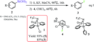 | ||
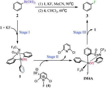
| Scheme 1 Bi(III)/Bi(V) redox catalyzed fluorination of arylboronic esters.33 | ||
Although Cornella and coworkers qualitatively proposed a reaction course and conducted experimentally mechanistic study on the unusual C–F bond reductive elimination process, several interesting open questions, such as the reasonable pathway for the generation of the active Bi(III)-aryl intermediate, the role of the employed base (i.e., KF), and the configuration of the Bi(V) intermediate, still unclear. We herein performed a thorough mechanistic study to elucidate the reaction mechanism of the fluorination of arylboronic esters mediated by the bismuth complexes (Scheme 1). The detailed reaction mechanism, in terms of energetics and structures, can clarify the important role of base KF, reveal the rate-determining step of the whole catalysis, and disclose the origin of the configuration transformation of the Bi(V) intermediate. Based on the mechanistic study, we further rationally designed the tethered bis-anionic aryl ligands based new catalysts with higher efficiency, which could be promising candidates for further experimental realization. In-depth mechanistic understanding of the target reaction and further catalyst design could be helpful for experimental chemists build more efficient bismuth complexes and develop new catalytic Bi(III)/Bi(V) redox process for the fluorination of aryl boronic esters.
Computational details
Geometry optimizations without symmetry restriction were carried out with the Gaussian 16 program.36 Specifically, geometry optimizations were firstly performed at the BP86 (ref. 37,38) /def2-SVP39–41 level with Grimme's GD3BJ dispersion corrections.42,43 The solvation effects of the experimentally used solvents (i.e., acetonitrile in transmetallation (TM) step, and chloroform in oxidative addition (OA) and reductive elimination (RE) process) were taken into consideration by using the Cramer–Truhlar continuum solvation model SMD.44,45 Subsequent frequency calculations were performed to evaluate enthalpy and entropy corrections at 298.15 K and ensured that all local minima had only real frequencies while a single imaginary frequency confirmed the presence of transition states. Intrinsic reaction coordinate (IRC)46 calculations were also conducted to verify the critical reaction steps involved in our proposed mechanisms. The energetic results were then improved by the single-point calculations at the BP86+D3/def2-TZVPP41 level with the solvation effects included. Unless otherwise stated, the BP86+D3/def2-TZVPP (smd, solvent = acetonitrile(TM)/ chloroform (OA and RE))//BP86+D3/def2-SVP (smd, solvent = acetonitrile(TM)/chloroform (OA and RE)) Gibbs free energies (in kcal mol−1) are used in the following discussion, while the electronic energies are also given in the related figures for reference. The partial charges q and bond order p of the molecules were obtained at the same level by using the NBO 7.0 program.47 The figures of noncovalent interaction analysis were prepared by using VMD48,49 and Multiwfn.50Results and discussions
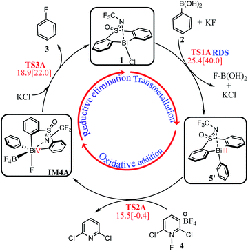
Inspired by Cornella and coworkers' study,33 we herein performed a detailed computational mechanistic study on the target reaction eqn (1) by using the aryl boronic ester 2 and the fluridizer as well as oxidant 1-fluoro-2,6-dichloropyridinium 4 as initial species under the catalytic effects of the bismuth catalyst 1. As shown in Scheme 2, the reaction course can divided into three stages: transmetallation with the assistance of KF activator generates the Bi(III)-aryl intermediate 5, which was characterized by X-ray crystallography (Stage I), followed by the oxidative addition process with the oxidant 4 gives the Bi(V) intermediate IM4A (Stage II), which was experimentally observed by 1H, 11B, 19F, and 13C nuclear magnetic resonance (NMR) and high-resolution mass spectrometry (HRMS).33 Finally, IM4A undergoes a reductive elimination step to produce the aryl fluoride product 3 and regenerate the catalyst 1 for the next catalytic cycle (Stage III).Stage I: transmetallation generates the Bi(III)-aryl intermediate 5
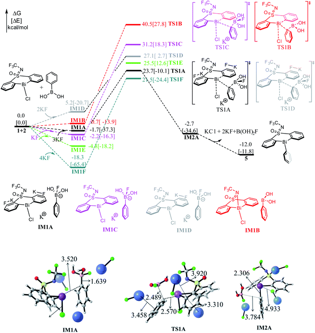
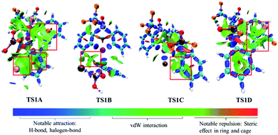
As shown in Fig. 1, the direct reaction of arylboronic 2 with the bismuth catalyst 1 can be easily excluded by the very high barrier of 40.5 kcal mol−1 of the transition state TS1B, in which the B–C rupture and the Bi–C bond formation proceeds concurrently. Considering KF was used as activator to promote the transmetallation process in experiment,33 we thus considered the role of KF. With the assistance of one equiv. base KF, the barrier can be reduced to 33.4 kcal mol−1 (i.e., IM1C → TS1C) respect to the former weak complex IM1C, implying the base KF plays an important role in improving the kinetics during the reaction course. We also considered the halogen substitution between KF and catalyst 1 releasing KCl and intermediate IM1E, but it can be readily prevented for the high barrier of 30.3 kcal mol−1 (i.e., IM1E → TS1E), which is mainly due to the strong electronegativity of fluorine resulting in the reluctant cleavage of the C–F bond during the transmetallation process. We further considered the use of two and three equiv. KF (denoted as 2KF and 3KF, respectively) as the mediators, and the barriers can be further decreased to 27.1 (i.e., IM1D → TS1D) and 25.4 kcal mol−1 (i.e., IM1A → TS1A), respectively. The key bond distances in the optimized TS1A (see Fig. 1), as well as the correct vibration mode of the only imaginary frequency, confirmed the correct transition state. We also explored the addition of four equiv. KF, yet the barrier of 39.8 kcal mol−1 (i.e., IM1F → TS1F) is much higher than that of TS1A. This suggests the employment of three equiv. KF is more efficient, which is in good agreement with the experimental observations.33To gain insight into the roles of the base KF (see Fig. 1 and Table 1), we further conducted the interaction region indicator51 analysis of the four important transition states with different equiv. of KF involved. As comparisons in Fig. 2, there are two strong π–cation (K+) interactions (i.e., π–cation distance is 3.458/3.310 Å) help to stabilize the structure of TS1A. However, there are only one π–cation interactions existed in TS1D, only one π–cation interactions appeared in TS1C, and only few weak interactions showed in TS1B, which should the origins of the higher barriers for the transition states TS1D, TS1C and TS1B.
| KF (equiv) | 3 equiv. (TS1A) | No KF (TS1B) | 1 equiv. (TS1C) | 2 equiv. (TS1D) | 4 equiv. (TS1F) |
|---|---|---|---|---|---|
| ΔΔG‡ (kcal mol−1) | 25.4 | 40.5 | 33.4 | 27.1 | 39.8 |
As shown in Fig. 1, the transmetallation process can be illustrated by the gradually elongated B–C bond distance and reduced Bi–C bond length, from 1.639, 3.520 Å in IM1A, 2.489, 2.570 Å in TS1A, and 3.784, 2.306 Å in IM2A, respectively. The formation of IM2A is exergonic by 2.7 kcal mol−1 relative to the initial reactions, implying the thermodynamically feasible process. The subsequent base and organoboron species release proceeds by releasing 9.3 kcal mol−1 (i.e., IM2A → 5) giving the experimentally observed key Bi(III)-aryl intermediate 5, which is 12.0 kcal mol−1 more stable than the initial reactants.
In fact, we also explored different reaction channels, where the aromatic ring of phenylboric acid 2 attack from above the Bi-atom of the catalyst 1. As detailed in Fig. S1,† we considered different reaction courses with or without the assistance of KF, and also the three equiv. KF involved pathway turned out to be the most favorable one with a barrier of 22.9 kcal mol−1 (i.e., IM1a → TS1a). It is slightly favorable than that of TS1A (i.e., 25.4 kcal mol−1, IM1A → TS1A), which is mainly due to the less steric hindrance of aromatic ring attacking from above. Nonetheless, the formation of the trivalent bismuth intermediate 5 is thermodynamically 5.5 kcal mol−1 more stable than 5′, which is mainly due to the favorable weak interactions between N atom and the aromatic ring in 5. Under the high reaction temperature (i.e., 90 °C) and the long reaction time, the intermediate 5′ can be easily transformed to the thermodynamically more stable intermediate 5. This also agrees well with experimentally observed intermediate 5, arising from the high reaction temperature (i.e., 90 °C) and the long reaction time.
Stage II: oxidative addition with the oxidant 4 gives the Bi(V)-complex IM4A
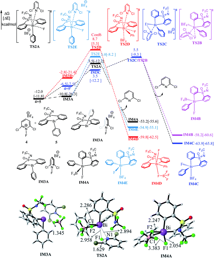
Fig. 3 shows the free energy profiles of Stage II together with some important optimized structures. With the addition of the 1-fluoro-2,6-dichloropyridinium 4, the Bi(III) intermediate 5 can be oxidized by 4 result in the pentavalent Bi(V) species, which was successfully detected in experiment.33 It is worthy of mentioning that the high-valent Bi(V) is the least unstable one among the Pnictogens (abbreviated Pn(V)) congeners due to inert pair effect.52,53 However, the weak coordination of the Bi atom and the lone pair of the S-bound nitrogen herein provide stabilization for the pentavalent Bi(V) species.The Bi(V) species normally exhibit two configurations, triangular bipyramid and tetrahedron. In this study, the tether ligand of catalyst 1 can control the geometry of high-valent Bi(V) during the reaction course. We herein considered the oxidative addition of the Bi(III) intermediate 5 with 4 from different orientations, which resulted in Bi(V) complexes with different configurations (see Table S1†). As compassions in Table S1,† the complex IM4C, in which the F- and BF4-speices in the cis-configuration, should be the most thermodynamically stable one. The extra stabilization of the cis-IM4C arises mainly from the weak coordination of the –OSNCF3– moiety to the Bi-center, which provides more electronic density to stabilize the highly electrophilic Bi(V) center.
As can be seen form Fig. 3, the oxidative addition of the Bi(III) complex 5 with the oxidant 4 overcome the barrier of 15.5 kcal mol−1 (i.e., 4 + 5 → TS2A), 17.0 kcal mol−1 (i.e., 4 + 5 → TS2E) and 20.7 kcal mol−1 (i.e., 4 + 5 → TS2D), respectively, leading to the important Bi(V) intermediate IM4A, IM4E, IM4D accompany with 2,6-dichloropyridinium release. Comparisons indicated the black pathway (i.e., 4 + 5 → TS2A) is kinetically more favorable. The formation of IM4A is highly exergonic by 53.2 kcal mol−1 relative to the initial reactant 2 and catalyst 1, implying the thermodynamically favorable process. This process can be manifested by the gradually elongated N–F bond distances, from 1.345 Å in IM3A to 1.629 Å in TS2A and reduced F–Bi bond distances from 2.958 Å in TS2A to 2.054 Å in IM4A, respectively.
The concerted reaction course has further been verified by the natural bond orbital (NBO) analysis on the structure of TS2A and IM4A. As shown in Table 2, the natural charge on Bi atom increases from 1.464 in TS2A to 2.100 in IM4A, while the natural charge of the N1 atom changes from −0.170 in TS2A to −0.974 in IM4A. Meanwhile, the Wiberg bond order of Bi–F1 bond increase from 0.149 in TS2A to 0.561 in IM4A, and the N1–F1 bond decrease from 0.575 in TS2A to 0.010 in IM4A, which indicates the Bi–F1 formation and N1–F1 bond cleavage occurs simultaneously. Meanwhile, considering the possible interconversion of intermediate 5 and 5′, we also explored the oxidative addition of the Bi(III) complex 5′ with the oxidant 4, which crosses a concerted transition state TS2C with a barrier of 17.5 kcal mol−1 (i.e., 4 + 5′ → TS2C). The geometric and energetic results indicated that the oxidation addition of Bi(III) intermediate 5 and 5′ is competitive, providing a new insight for the fluorination reaction.
| Bi species | |||||
|---|---|---|---|---|---|
| Natural charge q | Wiberg bond orders P | ||||
| TS2A | IM4A | TS2A | IM4A | ||
| Bi | 1.464 | 2.100 | Bi–C1 | 0.650 | 0.680 |
| Cl | −0.345 | −0.351 | Bi–N1 | 0.191 | 0.084 |
| F1 | −0.279 | −0.544 | Bi–F1 | 0.149 | 0.561 |
| F2 | −0.548 | −0.556 | Bi–F2 | 0.099 | 0.156 |
| N | −0.170 | −0.974 | N1–F1 | 0.575 | 0.010 |
Stage III: reductive elimination generates the product 3 and regenerates the active species
Subsequent to the formation of the high-valent Bi(V) intermediate (IM4A, IM4B, IM4C, IM4D) in Stage II, the reductive elimination process can be completed by coupling the individual F atom with exocyclic aryl group, which resembles to the concerted reductive eliminations pathway of the d-block elements mediated reactions. As shown in Fig. 4, the Bi(V) intermediate IM4A would be converted into IM4D due to the steric hindrance between –BF4 and –NCF3. Subsequently, the reductive elimination occurs via the three-membered-ring transition state TS3C (i.e., IM4D → TS3C) with a barrier of 18.9 kcal mol−1 leading to the intermediate IM5. The C–F bond formation process can be demonstrated by the gradually reduced C–F bond distances, from 3.383 Å in IM4A to 3.079 Å in IM4D to 2.144 Å in TS3C, and 1.353 Å in IM5 (see in Fig. S2†). Similarly, further NBO analysis (see Table S2†) on the structure of TS3A and IM4A illustrated the occurrence of reduction elimination process. The final active species 7 liberation proceed with exergonic by 2.6 kcal mol−1 (i.e., IM5 → 7). With the assistance of KCl released in the Stage I, the species 7 is converted to the catalyst 1. Similar to the discussions in Stage II, we also explored the reductive elimination process starting from the isomer IM4B and IM4D. However, the barriers for the located three-membered-ring transition states are predicated to be 19.7 kcal mol−1 (i.e., IM4B → TS3B), 21.9 kcal mol−1 (i.e., IM4C → TS3C) respectively, which are kinetically comparable to than that of 18.9 kcal mol−1 (i.e., IM4D → TS3D). The whole reaction relative to the initial reactant 2 and catalyst 1 is highly exoenergic by 102.8 kcal mol−1, which can provide enough thermodynamically driving force to reach the final product.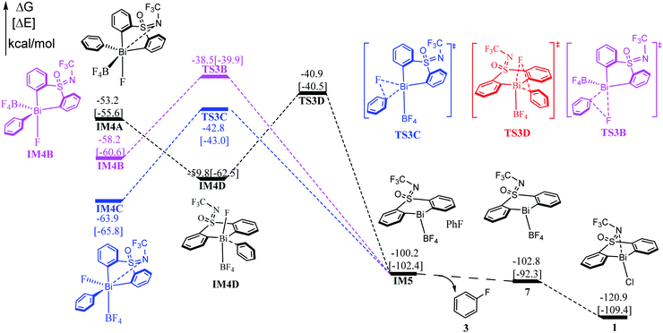 | ||
| Fig. 4 Computed free energy profiles (in kcal mol−1) for Stage III. The electronic energies (in kcal mol−1) are given in brackets for reference. | ||
On the basis of the discussions above, we assemble the three stages together to give the most favorable reaction course for the eqn (1) reaction. As shown in Scheme 3, transmetallation of the bridged bismacycle 1 with arylboronic 2 generates the Bi(III) halobismines 5 (Stage I). The following oxidative addition of 5 with the oxidant [Cl2pyrF]BF4 (4) gives the high-valent Bi(V) complex IM4A (Stage II). The subsequent reductive elimination will lead to the formation of the final product fluorobenzene 3, with catalyst 1 regeneration for the next catalytic cycle (Stage III). As indicated by the geometric and energetic results, each stage is kinetically and thermodynamically feasible. The transmetallation step, with a barrier of 25.4 kcal mol−1, should be the rate-determining step (RDS) during the whole catalysis. The whole reaction is exergonic by 102.8 kcal mol−1, which can provide the force to drive the reaction forward to reach the final product 3.
Rational design of new bismuth catalysts
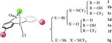
Our detailed mechanistic study revealed that the transmetallation step (i.e., IM1A → TS1A, ΔΔG≠ = 25.4 kcal mol−1) should be the rate-determining step (RDS) during the whole catalysis for the catalyst 1 mediated eqn 1. On the basis of the key rate-determining-step, we herein rationally design of several new catalysts (i.e., 1b–1f in Fig. 5) by employing the good tethered bis-anionic aryl ligands skeletons (X = NCF3 or O) with different substituents R, including the electron-donating group –OH and the electron-withdrawing group –CF3. On the other hand, we extended the bismuth center to stibium in the catalyst 1 resulting in the Sb-analogue 1g. The optimized geometries of these designed catalysts can be found in Fig. S3.†As shown in Table 3, the employment of the electron-donating –OH group leads to a higher barrier of 33.6 kcal mol−1 compared with that of catalyst 1 (i.e., 25.4 kcal mol−1), while the incorporation the electron-withdrawing group –CF3 in catalyst 1b gives a lower barrier of 24.0 kcal mol−1. The situation holds for the catalyst 1d–1f where the substituent X in the skeleton is O, where the use of electron-withdrawing group –CF3 is more efficient. This is in good agreement with the latest report of Cornella et al.,54 which demonstrated that the electron-deficient ligand scaffolds with electron-withdrawing groups can promote the aryl-F reductive elimination process. Considering antimony as a metal in the same group is cheaper than bismuth, we extended the rational design to the corresponding antimony complexes. However, the replacement of Bi-atom with Sb in the catalyst 1g shows a higher barrier of 38.8 kcal mol−1, suggesting the antimony analogue less efficient than the original catalyst 1.
| Catalyst | ΔΔG‡ (IM1 → TS1A) | q(E) |
|---|---|---|
| 1 | 25.4 | 1.315 |
| 1b | 33.6 | 1.314 |
| 1c | 24.0 | 1.345 |
| 1d | 25.8 | 1.306 |
| 1e | 34.4 | 1.306 |
| 1f | 24.8 | 1.337 |
| 1g | 38.8 | 1.208 |
As discussed in Stage II, NBO analysis is also performed to characterize the natural charge on the E-center (E = Bi/Sb) in the designed catalysts. As compared in Table 3, the natural charges on the Bi/Sb atom is contrariwise relative to the free energy barriers: the more charge carried, the lower barrier present. This means the free energy barrier for the RDS will decrease with the increasing of the natural charge on E-atom, because the more positive charges of Bi/Sb atom, the easier to couple with the electron-deficient arylboronic acid 2 and thus promoting the transmetallation process of the fluorination reactions. On the basis of the discussions above, our rationally designed catalysts, such as 1c and 1f, could substantially improve the efficiency for the fluorination of arylboronic esters, which will wait for future experiment verification.
Conclusions
In summary, density functional theory calculations were performed to elucidate the detailed reaction mechanism of the fluorination of arylboronic esters enabled by bismuth redox catalysis. Our study reveals that the reaction proceeds via the flowing mechanism: (i) the catalyst 1 reacts with phenylboric acid 2 to generate the Bi(III) intermediate 5 with the assistance of base KF. It should be emphasized that KF plays important role in stabilizing the transition state TS1A, which mainly due to the favorable π–cation interactions and the weak coordination of F to phenylboric acid in TS1A. (ii) The subsequent addition of the oxidant 1-fluoro-2,6-dichloropyridinium 4 leads to the formation of the Bi(V) intermediate IM4A. (iii) IM4A then undergoes reduction elimination process generates the final product fluorobenzene 3 and regenerates the catalyst 1 for the next catalytic cycle. Each stage is kinetically and thermodynamically feasible, and the transmetallation step with a barrier of 25.4 kcal mol−1 in Stage I is predicted to be the rate-determining step (RDS) during the whole catalysis. On the basis of the mechanistic study, we further rationally designed several new catalysts (i.e., 1b–1g), and catalyst 1c and 1f have great potential to improve the efficiency for the target fluorination reactions. Our detailed computational study and further rational catalyst design could provide insight to target reaction, which is helpful for the further development of new P-block elements mediated fluorinations.Conflicts of interest
There are no conflicts to declare.Acknowledgements
L. Z. acknowledges the financial support from National Natural Science Foundation of China (Grant no. 21973044), Natural Science Foundation of Jiangsu Province (Grant no. BK20211587), the “Jiangsu Specially-Appointed Professor Plan”, and Nanjing Tech University (Grant no. 39837123 and 39837132). We also appreciated the high performance center of Nanjing Tech University for supporting the computational resources.References
- K. Müller, C. Faeh and F. Diederich, Science, 2007, 317, 1881–1886 CrossRef PubMed.
- S. Purser, P. R. Moore, S. Swallow and V. Gouverneur, Chem. Soc. Rev., 2008, 37, 320–330 RSC.
- P. Jeschke, ChemBioChem, 2004, 5, 570–589 CrossRef CAS PubMed.
- M.-H. Hung, W. B. Farnham, A. E. Feiring and S. Rozen in Fluoropolymers 1: Synthesis, Hougham, G., Cassidy, P. E., Johns, K. and Davidson, T., eds., Springer US, Boston, MA, 2002, pp. 51–66 Search PubMed.
- S. M. Ametamey, M. Honer and P. A. Schubiger, Chem. Rev., 2008, 108, 1501–1516 CrossRef CAS PubMed.
- T. Furuya, J. E. M. N. Klein and T. Ritter, Synthesis, 2010, 2010, 1804–1821 CrossRef PubMed.
- V. V. Grushin, Acc. Chem. Res., 2010, 43, 160–171 CrossRef CAS PubMed.
- K. L. Kirk, Org. Process Res. Dev., 2008, 12, 305–321 CrossRef CAS.
- T. Furuya, C. A. Kuttruff and T. Ritter, Curr. Opin. Drug Discovery Dev., 2008, 803–819 CAS.
- T. D. Beeson and D. W. C. MacMillan, J. Am. Chem. Soc., 2005, 127, 8826–8828 CrossRef CAS PubMed.
- M. Marigo, D. Fielenbach, A. Braunton, A. Kjærsgaard and K. A. Jørgensen, Angew. Chem., Int. Ed., 2005, 44, 3703–3706 CrossRef CAS PubMed.
- D. D. Steiner, N. Mase and C. F. Barbas III, Angew. Chem., Int. Ed., 2005, 44, 3706–3710 CrossRef CAS PubMed.
- P. M. Pihko, Angew. Chem., Int. Ed., 2006, 45, 544–547 CrossRef CAS PubMed.
- J.-A. Ma and D. Cahard, Tetrahedron: Asymmetry, 2004, 15, 1007–1011 CrossRef CAS.
- G. Balz and G. Schiemann, Ber. Dtsch. Chem. Ges., 1927, 60, 1186–1190 CrossRef.
- S. D. Schimler, S. J. Ryan, D. C. Bland, J. E. Anderson and M. S. Sanford, J. Org. Chem., 2015, 80, 12137–12145 CrossRef CAS PubMed.
- G. C. Finger and C. W. Kruse, J. Am. Chem. Soc., 1956, 78, 6034–6037 CrossRef CAS.
- A. C. Sather, H. G. Lee, V. Y. De La Rosa, Y. Yang, P. Müller and S. L. Buchwald, J. Am. Chem. Soc., 2015, 137, 13433–13438 CrossRef CAS PubMed.
- P. S. Fier and J. F. Hartwig, J. Am. Chem. Soc., 2012, 134, 10795–10798 CrossRef CAS PubMed.
- P. Tang, W. Wang and T. Ritter, J. Am. Chem. Soc., 2011, 133, 11482–11484 CrossRef CAS PubMed.
- S. Yamada, A. Gavryushin and P. Knochel, Angew. Chem., Int. Ed., 2010, 49, 2215–2218 CrossRef CAS PubMed.
- J. W. B. Fyfe and A. J. B. Watson, Chem, 2017, 3, 31–55 CAS.
- A. Biffis, P. Centomo, A. Del Zotto and M. Zecca, Chem. Rev., 2018, 118, 2249–2295 CrossRef CAS PubMed.
- C. C. C. Johansson Seechurn, M. O. Kitching, T. J. Colacot and V. Snieckus, Angew. Chem., Int. Ed., 2012, 51, 5062–5085 CrossRef CAS PubMed.
- A. R. Mazzotti, M. G. Campbell, P. Tang, J. M. Murphy and T. Ritter, J. Am. Chem. Soc., 2013, 135, 14012–14015 CrossRef CAS PubMed.
- T. Furuya and T. Ritter, Org. Lett., 2009, 11, 2860–2863 CrossRef CAS PubMed.
- P. S. Fier, J. Luo and J. F. Hartwig, J. Am. Chem. Soc., 2013, 135, 2552–2559 CrossRef CAS PubMed.
- Y. Ye and M. S. Sanford, J. Am. Chem. Soc., 2013, 135, 4648–4651 CrossRef CAS PubMed.
- T. Furuya, A. E. Strom and T. Ritter, J. Am. Chem. Soc., 2009, 131, 1662–1663 CrossRef CAS PubMed.
- N. D. Ball and M. S. Sanford, J. Am. Chem. Soc., 2009, 131, 3796–3797 CrossRef CAS PubMed.
- R. Mohan, Nat. Chem., 2010, 2, 336 CrossRef CAS PubMed.
- E. T. Ollevier, Bismuth-Mediated Organic Reactions, Springer, 2012 Search PubMed.
- O. Planas, F. Wang, M. Leutzsch and J. Cornella, Science, 2020, 367, 313–317 CrossRef CAS PubMed.
- T. Ooi, R. Goto and K. Maruoka, J. Am. Chem. Soc., 2003, 125, 10494–10495 CrossRef CAS PubMed.
- S. A. Lermontov, I. M. Rakov, N. S. Zefirov and P. J. Stang, Tetrahedron Lett., 1996, 37, 4051–4054 CrossRef CAS.
- M. J. Frisch, G. W. Trucks, H. B. Schlegel, G. E. Scuseria, M. A. Robb, J. R. Cheeseman, G. Scalmani, V. Barone, G. A. Petersson, H. Nakatsuji, X. Li, M. Caricato, A. V. Marenich, J. Bloino, B. G. Janesko, R. Gomperts, B. Mennucci, H. P. Hratchian, J. V. Ortiz, A. F. Izmaylov, J. L. Sonnenberg, D. Williams-Young, F. Ding, F. Lipparini, F. Egidi, J. Goings, B. Peng, A. Petrone, T. Henderson, D. Ranasinghe, V. G. Zakrzewski, J. Gao, N. Rega, G. Zheng, W. Liang, M. Hada, M. Ehara, K. Toyota, R. Fukuda, J. Hasegawa, M. Ishida, T. Nakajima, Y. Honda, O. Kitao, H. Nakai, T. Vreven, K. Throssell, J. A. Montgomery Jr, J. E. Peralta, F. Ogliaro, M. J. Bearpark, J. J. Heyd, E. N. Brothers, K. N. Kudin, V. N. Staroverov, T. A. Keith, R. Kobayashi, J. Normand, K. Raghavachari, A. P. Rendell, J. C. Burant, S. S. Iyengar, J. Tomasi, M. Cossi, J. M. Millam, M. Klene, C. Adamo, R. Cammi, J. W. Ochterski, R. L. Martin, K. Morokuma, O. Farkas, J. B. Foresman, and D. J. Fox, Gaussian 16, Gaussian, Inc., Wallingford CT, 2016 Search PubMed.
- A. D. Becke, Phys. Rev. A, 1988, 38, 3098–3100 CrossRef CAS PubMed.
- J. P. Perdew, Phys. Rev. B, 1986, 33, 8822–8824 CrossRef PubMed.
- Y. Zhao and D. G. Truhlar, Theor. Chem. Acc., 2008, 120, 215–241 Search PubMed.
- F. Weigend, Phys. Chem. Chem., 2006, 8, 1057–1065 Search PubMed.
- F. Weigend and R. Ahlrichs, Phys. Chem. Chem., 2005, 7, 3297–3305 Search PubMed.
- S. Grimme, S. Ehrlich and L. Goerigk, J. Comput. Chem., 2011, 32, 1456–1465 CrossRef CAS PubMed.
- S. Grimme, J. Antony, S. Ehrlich and H. Krieg, J. Chem. Phys., 2010, 132, 154104 CrossRef PubMed.
- M. Cossi, N. Rega, G. Scalmani and V. Barone, J. Comput. Chem., 2003, 24, 669–681 CrossRef CAS PubMed.
- A. V. Marenich, C. J. Cramer and D. G. Truhlar, J. Phys. Chem. B, 2009, 113, 6378–6396 CrossRef CAS PubMed.
- K. Fukui, Acc. Chem. Res., 1981, 14, 363–368 CrossRef CAS.
- E. D. B. Glendening, J. K., A. E. Reed, J. E. Carpenter, J. A. Bohmann, C. Morales, P. Karafiloglou, C. R. Landis and F. Weinhold, NBO 7.0, Theoretical Chemistry Institute, University of Wisconsin, Madison, 2018 Search PubMed.
- W. Humphrey, A. Dalke and K. Schulten, J. Mol. Graphics, 1996, 14, 33–38 CrossRef CAS PubMed.
- E. R. Johnson, S. Keinan, P. Mori-Sánchez, J. Contreras-García, A. J. Cohen and W. Yang, J. Am. Chem. Soc., 2010, 132, 6498–6506 CrossRef CAS PubMed.
- T. Lu and F. Chen, J. Comput. Chem., 2012, 33, 580–592 CrossRef CAS PubMed.
- T. Lu and Q. Chen, Chem. Methods, 2021, 1, 231–239 CrossRef.
- R. S. Drago, J. Phys. Chem., 1958, 62, 353–357 CrossRef CAS.
- R. T. Sanderson, Inorg. Chem., 1986, 25, 1856–1858 CrossRef CAS.
- O. Planas, V. Peciukenas, M. Leutzsch, N. Nöthling, D. A. Pantazis and J. Cornella, J. Am. Chem. Soc., 2022, 144(32), 14489–14504 CrossRef CAS PubMed.
Footnote |
| † Electronic supplementary information (ESI) available. See https://doi.org/10.1039/d2ra04296g |
| This journal is © The Royal Society of Chemistry 2022 |

