
 Open Access Article
 This Open Access Article is licensed under a Creative Commons Attribution-Non Commercial 3.0 Unported Licence
Nanostructured SiO2 material: synthesis advances and applications in rubber reinforcement
Agraw Mulat Muhammud * and
Neeraj Kumar Gupta
* and
Neeraj Kumar Gupta
Department of Applied Chemistry, Adama Science and Technology University, Ethiopia. E-mail: agrawchem@gmail.com
First published on 23rd June 2022
Abstract
Silica is a commercially significant material due to its extensive use in widespread applications and products. Synthetic amorphous silica (SAS) is a form of SiO2 that is intentionally manufactured and has been produced and marketed for decades without significant changes in its physico-chemical properties. The industrial production of nanostructured SiO2 is nowadays challenged by the expensive raw material use and high energy consumption. The search for non-petroleum-based fillers such as nanostructured SiO2, which are environmentally friendly, cheap, abundant, renewable, and efficient, has been initiated nowadays. Therefore, a large number of research activities have been carried out so far for the preparation of SAS from potential alternate precursors, i.e., synthetic chemicals, biogenic, and mineral ore resources. Reinforcement of rubbers with nanostructured SiO2 fillers is a process of great practical and technological importance for improving their mechanical, dynamic, and thermal properties. The efficiencies of SiO2 reinforcement correlate with different factors such as filler structure, surface area, rubber–filler interactions, and filler–filler interactions with their effects. This review paper discusses the recent synthesis advances of nanostructured SiO2 from synthetic chemicals, biogenic and mineral ore resources, their physical characteristics, and applications in rubber reinforcement, overcoming challenges. Finally, summary and future work recommendations have been mentioned well for future researchers.
1. Introduction
With the rapid emergence of the field of nanotechnology, regulations specific to nanomaterials are under development. One of the key issues hindering regulation is a lack of agreement on the definition of what constitutes a nanomaterial. Currently, the most comprehensive and internationally recognized definition of nanomaterials is presented by the International Standards Organization (ISO). The ISO definition distinguishes between two subgroups, nano-objects and nanostructured materials, and defines them as:1 nano-objects are materials that exist in a defined singular form that have at least one dimension in the nano-scale (<100 nm), which includes nano-particles (3D in nano-scale), nanofibers (2D in nano-scale), and nano-plates (1D in nano scale). Nanostructured materials are materials that have structural features on the nano-scale but whose particle size is typically greater than 100 nm. Examples of these are materials that primarily exist in aggregated and/or agglomerated forms.Silica is a commercially significant material due to its extensive use in widespread applications and products. The base unit of the structure of the macromolecular network nSiO2 is the [SiO4]4− tetrahedron. Synthetic amorphous silica (SAS) is a form of SiO2 that is intentionally manufactured and has been produced and marketed for decades without significant changes in its physico-chemical properties. SAS is in the form of white dry powders or dispersions of these powders are used in a multitude of industrial applications, i.e., an additive in rubber. It is also approved to be used in consumer products, i.e., food, cosmetics, and pharmaceuticals. To define, SAS in powder form is a nanostructured material according to the technical specification of ISO TS 80004-1. The aggregate is the smallest indivisible unit upon dispersion. There are three types of synthetic amorphous SiO2 produced at the industrial scale: fumed SiO2, precipitated SiO2, and SiO2 gel. Of these three types of amorphous SiO2, precipitated SiO2, whose production started in the 1940s, has the greatest commercial importance. Precipitated SiO2 is a finely divided white powder sparingly soluble in water and composed of aggregates up to approximately 1 mm in diameter.
The current commercial precipitated SiO2 is produced by a wet SiO2 production route or sol–gel process, in which an aqueous alkali metal silicate solution is neutralized with acid (e.g., H2SO4), releasing SiO2 and nH2O in a reaction tank to produce a slurry of SiO2. The most commonly used aqueous alkali silicate is water glass (Na2O·nSiO2; n = 2–4), which is produced by melting quartz sand with soda at about 1300 °C.2 Reaction conditions are manipulated according to the particle size required. Hydrogen bonding among particles will form clusters or aggregates, and these aggregates may loosely bond as agglomerates. Fumed silica (SiO2), also known as pyrogenic silica (SiO2), is mainly produced by reacting any SiO2 source with any carbon source in an electric arc furnace at approximately 1900 °C undergoing carbothermal reduction to metallurgical grade silicon, Si (met), which is then treated with HCl to produce SiCl4. The SiCl4, in turn, is combusted in a hydrogen–oxygen flame to produce fumed SiO2 plus byproduct HCl.3 Both synthetic amorphous silica commercial processes require expensive precursor use, corrosive, toxic and polluting side product generation, the need for tailoring properties of products, high-temperature and energy-intensive steps make production processes expensive in which further synthesis advancement has been the subject of much of the ongoing researches. Many researchers have devoted studies to replace the expensive source of synthetic silica with one that is cheaper and renewable, i.e., biogenic and mineral ore resources. In addition to this, researchers extensively worked on the promotion of widespread preparation methods with an emphasis on sol–gel synthesis parameter optimization to tailor the nanostructured SiO2 product physicochemical properties for specific applications, particularly for rubber reinforcement.
Elastomers or rubbers, whether natural or synthetic, are not usually used in their pure form due to insufficient practical physico-mechanical properties. Fillers are extensively used in the rubber industry to improve service efficiency and ease of processing, and their addition results in a fundamental change in the properties of rubber. According to the kinetic theory of elasticity, the rubber modulus (with no fillers) increases with the rise of temperature; the addition of fillers significantly changes the temperature coefficient of modulus and may even alter the sign of the coefficient, resulting in a decrease of the modulus with increasing temperature.
Fillers are classified based on chemical composition and their influence on rubber properties. Further, in rubber compounding, they can be divided primarily into three categories in accordance with their reinforcing effect: inactive, semi-active, and very active. The term active signifies the degree of reinforcement, i.e., the influence of the filler on the viscosity of the compound and the resulting mechanical properties. The main characteristics that determine the reinforcing effect of fillers are their structure and surface properties. Active fillers have a large relative surface area and high structure, providing strong physical and chemical interaction between the filler and polymer. However, a highly active filler surface leads to strong interparticle forces, which negatively influence the processing behavior as a result of the agglomeration of filler particles during mixing and storage.4 Common to composites' preparation and modification mechanisms, several factors influence the property profiles, which lie between those of pure rubber and filler or processability. These include volume fraction, particle dimension and geometry, dispersion quality, the interaction between rubber and fillers or among fillers, and, if applicable, the degree of orientation of fillers for anisotropic properties. These factors, in turn, affect one another, and synergy is achieved if an optimum balance is reached.5
The most common fillers used in the rubber industry are the carbon family of materials (carbon black, carbon fiber (CF), carbon nanotubes (CNTs), graphite and graphene), inorganic particles (nanoclays, polyhedral oligomeric silsesquioxane (POSS), SiO2, calcium carbonate (CaCO3), talc, zinc oxide (ZnO), titanium oxide (TiO2), alumina (Al2O3), halloysite), and biofillers (cellulose, husk, wood, coir).5–7 However, the large volume applications of rubber, certainly those involving high elasticity and mechanical properties, including stiffness, strength, toughness, abrasion resistance, anti-scratching property, or friction behavior, etc., are reinforced by carbon black and precipitated SiO2 as the dominant fillers. Even if both carbon black and nanostructured silica are the dominant fillers for rubbers, the search for non-petroleum based filler and a promising efficiency for reducing the rolling resistance of rubber nanocomposites in tire tread makes nanostructured silica an important and economical filler in the rubber industry. The potential of lowering the rolling resistance makes silica a promising reinforcement in the fabrication of green tire tread.8 Modern fuel-saving tire treads are commonly reinforced by silica due to the fact that this leads to lower rolling resistance and higher wet grip compared to carbon black-filled alternatives, which may have the potential to improve tire performance further.
Very limited review works have been reported yet on the synthesis advances of nanostructured SiO2 material from cheap, renewable potential precursors and characteristic features of SiO2 filler for rubber reinforcement. This paper highlights the synthesis advancement of nanostructured silica from potential precursors with emphasis on soft template based synthetic chemical precursors, biogenic, and mineral ore resources. The review also describes the reinforcement of rubber with nanostructured SiO2 fillers due to its mechanical, dynamic, and thermal properties and correlates with different factors like filler structure, surface area, filler–filler, and rubber–SiO2 filler interactions effects on SiO2 filled rubber nanocomposites with the overcoming challenges, which are reported in different works published so far.
2. Research advances for the synthesis of nanostructured SiO2
The widespread preparation methods, e.g., hydrothermal, sol–gel, precipitation, etc., generally tend to yield spherical or slightly irregular nanostructures, which may or not be manipulated to design different physical shapes (e.g., elongated structures9 and rods of different aspect ratios, etc.). SiO2 nanofibers have been produced by electro spinning10 or by chemical vapor deposition (CVD).11The properties of SAS are strongly dependent on the parameters of synthesis, such as the reactant concentration, reaction temperature, time of precipitation, pH range, type and addition of surfactants, solvents, and modes of washing and drying. These parameters influence the development of the size and uniformity of the SiO2 particles, their morphology, aggregation, pore dimensions and volume, and specific surface area. These, in turn, influence the properties of the designed structures and the consideration of the properties along with the high surface area enables their use for a wide range of applications. The preparation of amorphous SiO2 nanostructures has been studied by various research groups using different categories of precursors: synthetic chemicals, biogenic, and naturally occurring mineral resources. The research efforts in these three categories are briefly discussed in the following sections.
2.1. Synthesis of SAS using synthetic chemicals
Dispersed, amorphous, and uniform SiO2 nanostructures are of interest due to their simple preparation and potential applications in various industries as they may be used as effective materials for improving the strength, flexibility, durability, workability, etc. The most common precursors used at the laboratory scale are tetraethyl or tetra methyl orthosilicate (TEOS or TMOS) or inorganic sodium silicate. Different synthetic strategies have been applied to prepare these structures: the modified Stober method,12–16 combustion techniques,17 chemical vapor deposition,18 aerosol spray,19 and emulsion20,21 methods. Various types of morphologies such as hexagonal, cubic, lamellar, and wormhole like mesostructures have been synthesized using these methods and TEOS or TMOS as precursors. It is well-known that spherical dispersed silica nanoparticles can be prepared using the sol gel method with TEOS or TMOS or sodium silicate precursors.The main advantage of the sol–gel method is the control of the particle size at the nano level and morphology development of SiO2 nanostructures by changing the concentration of reagents, type of catalyst, temperature, reaction conditions, etc. Many efforts have been made to control the particle size and morphology of SiO2 nanoparticles through the use of different types of surfactants as templates. In the synthesis of mesoporous materials (such as SiO2), organic surfactant molecules play an important role in generating porosity within the building blocks and thus act as the endotemplate or structure directing agent (SDA). In this regard, the soft templating method has been the most successful pathway for the synthesis of ordered and disordered mesoporous matrices.
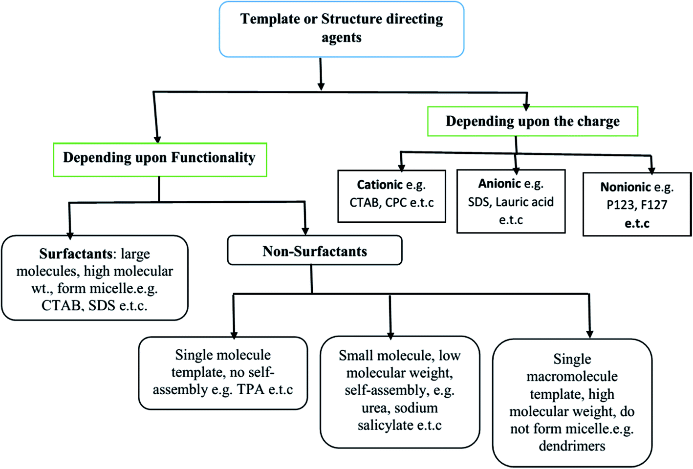
The SDAs can be of different types: (i) surfactants may be employed as SDA, wherein the essential feature is the coexistence of chemically bonded non-polar hydrocarbon ‘tail’ and a polar ‘head’ group in a molecule. These molecules have high molecular weight and form aggregates in the solvent to form self-assembled micelles,22–24 (ii) non-surfactant single molecules, which may or not form self-assembly bearing hydrophobic–hydrophilic groups in a single molecule, but act as templates in the design of mesopores in a material;25 and (iii) dendrimers or polymers (macromolecular single molecule having high molecular weight).26,27 All three types of templates are soft templates. Fig. 1 shows the classification of soft templates,28 some of which are used to study structure development in SiO2 nanostructures.
 | ||
| Fig. 1 Various categories of soft templates.28 | ||
Different SDAs, depending on their structure and nature, have different critical micelle (CMC) values in water or solvent.29,30 Beyond the CMC values, the self-assembly of micelles occurs to form a 3D spherical or 2D rod like array with further increasing concentration, and this self-assembly helps in pore generation (Fig. 2). These self-assembled micelles are formed by the association of individual amphiphilic templating molecules bonded through weak forces like van der Waals, hydrogen bonding, etc., but without covalent linkage between the amphiphiles.31
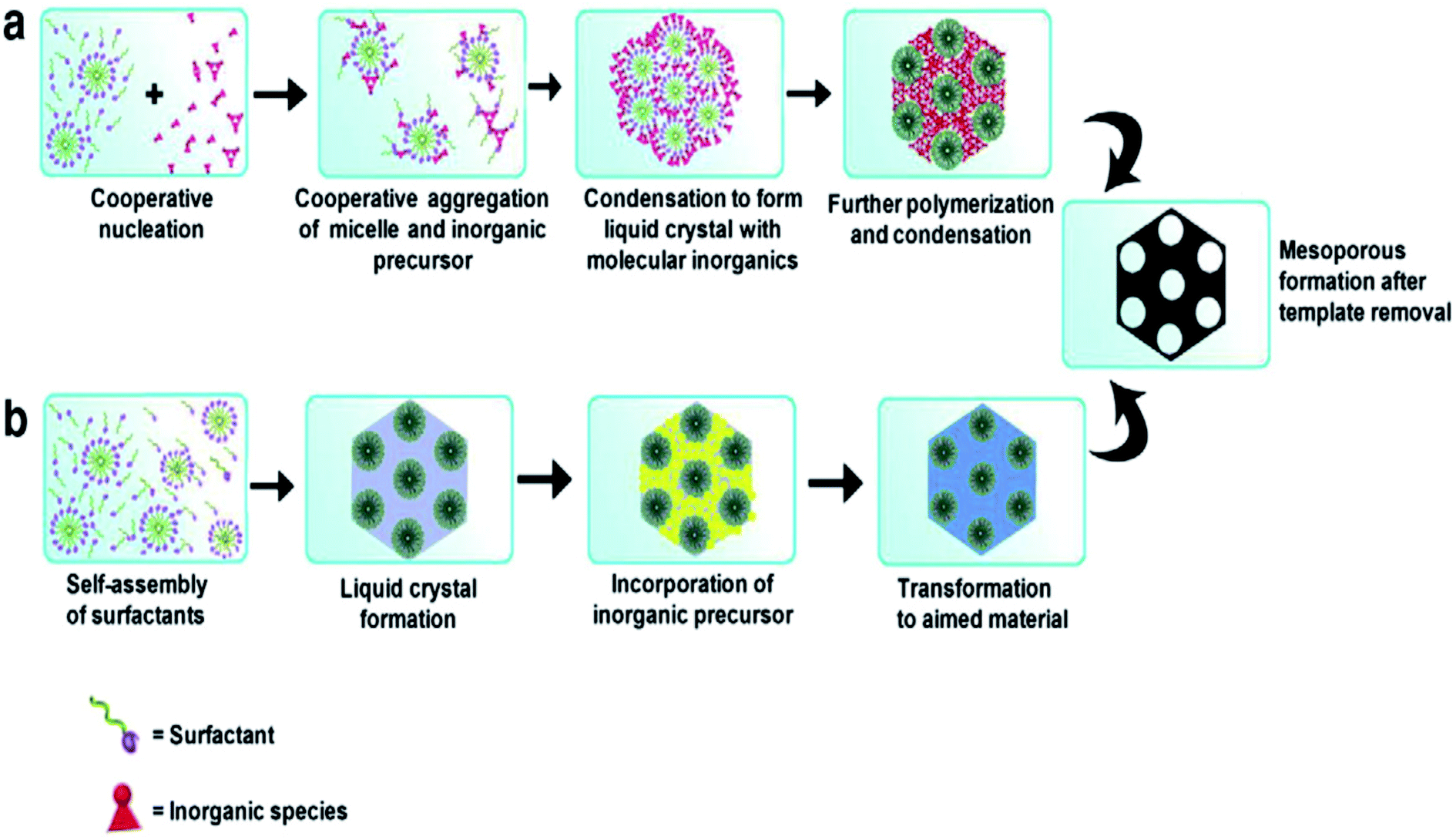 | ||
| Fig. 2 Formation of mesoporous structures: (a) via co-operative self-assembly, (b) via true liquid–crystal templating process.28,31 | ||
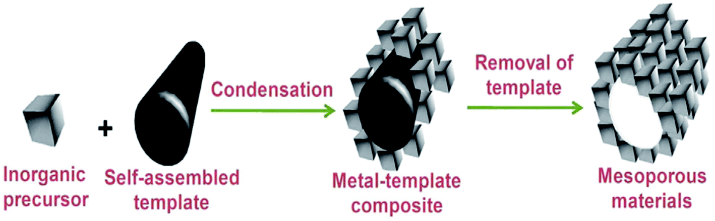
Thus, SDA molecules are placeholders: what becomes the void space to produce a nanoporous material. They not only allow controlling the variation of pore size but also the shape of the pores, i.e., the total architecture of the template molecule whose size and shape are imprinted in the porous solid, as shown in Fig. 3.32
 | ||
| Fig. 3 A common pathway for the formation of mesoporous solid.32 | ||
The concentration of SDA also influences the shape and size of the nanostructures, as shown by the example of using CTAB as SDA in Fig. 4.33,34
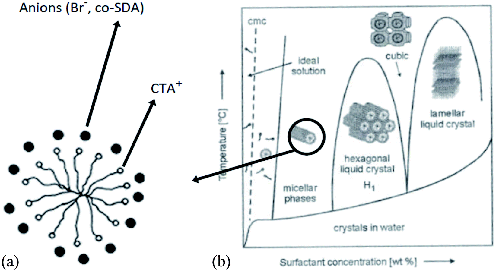 | ||
| Fig. 4 Arrangement of anions around CTAB cylindrical micelle (section) (a); phase diagram of the shape of CTAB micelles, (b) structure and size development with SDA concentration.33,34 | ||
The hydrothermal method, actually a sol–gel process, consists of a number of steps. Initially, the formation of surfactant self-assembly occurs via the true liquid crystal template (TLCT) mechanism to form a homogeneous surfactant solution in an aqueous solvent media. Then, the silicate precursor, TEOS or TMOS or sodium silicate, is added to the surfactant solution when it gets hydrolyzed under the acidic or basic conditions to form a silicate oligomer sol. These oligomers then condense with surfactant micelles via cooperative assembly and aggregation to form an inorganic–organic hybrid, which eventually precipitates in the form of a gel. The gel is treated hydrothermally for further condensation, solidification, and reorganization of the material to an ordered arrangement.35,36 After a certain time of ageing, the resultant product is cooled, filtered, washed, and dried. The process is shown in Fig. 5.34,37 Ordered mesostructured SiO2 material is obtained from this as-synthesized solid after the removal of surfactant through calcination or solvent extraction.
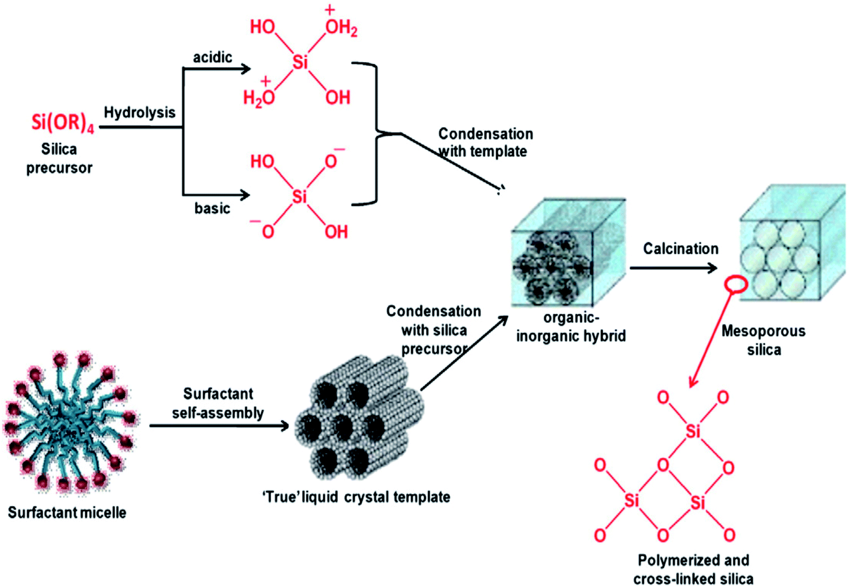 | ||
| Fig. 5 Stepwise formation of mesoporous SiO2 material.34,37 | ||
Some of the research efforts using different precursors and without and with SDAs are summarized in Table 1.
| Sl No. | Precursor | BET surface area (m2 g−1) | Particle size (nm) | Pore size (nm) and volume (cm3 g−1) | Method | Ref. |
|---|---|---|---|---|---|---|
| 1 | Sodium silicate solution | 160.29 | — | 0.57 | Sol–gel method | 38 |
| Precipitation by HCl | ||||||
| 2 | Sodium silicate solution | — | — | — | Precipitation by H2SO4 at pH 4, 7, and 9 | 39 |
| 3 | Tetraethylorthosilicate | — | — | — | Sol–gel method | 40 |
| Non-capping and PVA capping of particles | ||||||
| 4 | Tetraethylorthosilicate | — | 60 to 100 | — | Sol–gel method | 41 |
| Ablation | ||||||
| Crushing | ||||||
| 5 | Tetraethylorthosilicate | — | — | — | Sol–gel method assisted by freeze drying | 42 |
| Capping agent: polyethylene glycol | ||||||
| 6 | Tetraethylorthosilicate | — | ∼150 to 190 | — | Modified Stober method | 43 |
| Particles modified by silane coupling agents with different alkyl chain lengths | ||||||
| - Dimethyldichlorosilane (CH3)2SiCl2) | ||||||
| - 3-Methacryloxypropyl-trimethoxy silane (KH570) | ||||||
| - 3-Aminopropyl-triethoxy silane (KH550) | ||||||
| 7 | Tetraethylorthosilicate | 0 CTAB: 45 H2O: 7.8 | 0 CTAB: 45 H2O: spheres 700–800 | 0 CTAB: 45 H2O: size: n.a.; volume: 0.01 | Sol gel method | 44 |
| 0.1 CTAB: 45 H2O: 308 | 0.1 CTAB: 45 H2O: spheres 600–700 | 0.1 CTAB: 45 H2O: size: 2.9; volume: 0.21 | Surfactant: CTAB | |||
| 8 | Tetraethylorthosilicate | — | Average: 79.68 to 87.35 | — | Sol–gel method | 45 |
| Precipitation by acetic acid | ||||||
| 9 | Water glass | — | Less than 100: avg ∼ 25–43 | — | Precipitation by HCl | 46 |
| 10 | Tetraethylorthosilicate | Reaction parameters dependent: 515.4 to 1164.9 | — | Reaction parameters dependent | Precipitation method | 47 |
| - Pore size: 2.7 to 4.9 | ||||||
| - Pore vol: 0.6 to 1.5 | ||||||
| — | Porogen; n-octadecyl-trimethoxysilane (C18TMS) | |||||
| 11 | Sodium silicate | — | CTAB: 90 to 250 with an average of 148 | — | Precipitation from wet–gel | 48 |
| DTAB: 100 to 350 with an average of 212 | Cationic surfactants | |||||
| - CTAB | ||||||
| - DTAB | ||||||
| 12 | Tetraethylorthosilicate | — | DTAB: ∼140 | — | Sol–gel method | 49 |
| TTAB: ∼95 | Cationic surfactants | |||||
| - DTAB | ||||||
| - TTAB | ||||||
| - CTAB | ||||||
| CTAB: ∼55 | ||||||
| 13 | Tetraethylorthosilicate | n-SiO2: 5.5 | Span 60: ∼80 | — | Sol gel method | 50 |
| n-SiO2 (Span 20): 6.2 | Span 20, Span 40 and Span 60: range 150-80 | Nonionic surfactants | ||||
| - Span 20 | ||||||
| n-SiO2 (Span 40): 9.1 | - Span 40 | |||||
| n-SiO2 (Span 60): 11.5 | - Span 60 | |||||
| n-SiO2 (pH 10): 6.5 | ||||||
| n-SiO2 (pH 11): 5.3 | ||||||
| n-SiO2 (pH 12): 4.9 | ||||||
| 14 | Sodium silicate | Up to 130 | Majority of primary particles: ∼15 to 30 | — | Precipitation by coagulation with H2SO4 | 51 |
| Tendency to form bigger particles (aggregate) |
2.2. Extraction and preparation of amorphous SiO2 from biogenic sources
Much of the world's agricultural waste contains SiO2, and the search for a practical way to extract it stretches back almost 80 years. The extraction of amorphous SiO2 from biogenic sources, especially the third category of biomass, i.e., true bio-waste, which means they are generated as a byproduct of another useful resource, is a hot area of research. Research focus has and is on approaches to find the source of SiO2 that is safe, cheap, and more environmentally friendly as an alternative to the commercial activities of production. Research efforts have involved the use of agricultural waste such as rice husk, rice straw, coffee, cane husk, etc., as precursors for the preparation of pure SiO2 in either the amorphous or crystalline form. Table 2 shows the ash and SiO2 content of some plants.52,53 The major biogenic source of research is rice husk and its ash. The world paddy production in 2017 was 769.65 million tons (503.6 million tons, milled basis) and is produced in many regions of the world.54 On average, 28% of the rice paddy is husk, giving an annual total global production in excess of 212.5 million tons. The rice husk (rice hull) is formed from hard materials, including SiO2 and lignin, which protect the seed. Each kilogram of milled white rice results in roughly 0.28 kg of rice husk as a by-product of rice production during milling.| Plant | Part of plant | Ash% | Silica% | Reference |
|---|---|---|---|---|
| Cane | Husk | — | 08.00 | 53 |
| Coffee | Husk | — | 12.00 | 53 |
| Bagasse | — | 14.71 | 73.00 | 52 |
| Bamboo | Nodes (inner portion) | 1.44 | 57.40 | 52 |
| Bread fruit tree | Steam | 8.64 | 81.80 | 52 |
| Corn | Leaf sheath | 12.15 | 64.32 | 52 |
| Lantana | Leaf and stem | 11.24 | 23.38 | 52 |
| Rice husk | — | 22.15 | 93.00 | 52 |
| Rice straw | — | 14.65 | 82.00 | 52 |
| Sorghum | Leaf sheath epidermis | 12.25 | 88.75 | 52 |
Over the years, different preparation procedures have been investigated: the dry bio-digestion process involving the anaerobic digestion of rice straw to produce both bioenergy and SiO2 enriched solids followed by calcination and washing to obtain high purity SiO2,52,53 precipitation method (before and after calcination of the precursor),55 sol–gel process using rice husk ash as a low cost precursor and chitosan as template for the preparation of bimodal macroporous SiO2 (BPS),56 pre and post strong acid leaching and alkali treatment of rice husk followed by calcination to prepare relatively pure activated SiO2, were investigated,57,58 SiO2 gel from rice husk derived sodium silicate and neutralization by microwave heating,59 combustion of rice husk in a fluidized bed to obtain SiO2 white higher in quality than that of GB-precipitated SiO2 and approaches that of pyrogenic SiO2 except for specific surface area and iron content60 and high-purity SiO2 from rice husks using a carboxylic acid and citric acid leaching process followed by calcination,59,61 etc.
Some representative research efforts utilizing different biogenic precursors for the extraction of amorphous SiO2 are summarized in Table 3.
| Sl. No. | Biogenic precursor | BET surface area (m2 g−1) | Particle size (nm) | Pore size (nm) and pore volume (cm3 g−1) | Method | Ref. |
|---|---|---|---|---|---|---|
| 1 | Palm oil mill fly ash | pH 8.75 to 8.30: 140.75 to 79.91 | 10.67 ± 1.44 μm | — | Sol gel precipitation | 62 |
| pH 9.5; RT to 95 °C: 50–140 | Gel destabilization by CO2 | |||||
| Mechanical defragmentation of SiO2 cake | ||||||
| 2 | Barley grain waste | Acid treated barley, 700 °C: 323 | ∼150 | Pore size: 22 | Waste washed, dried and dried powdered into fine particles | 63 |
| Pore volume: 1.045 | Fine particles powdered boiled in HNO3, rinsed with distilled water, and dried | |||||
| Dried sample refluxed with HCl after which apportioned into four lots and heated at 400, 500, 600, 700 °C | ||||||
| 3 | Sugarcane waste ash | 131 | <20 | — | Ash pretreatment with acid, washing and sieving | 64 |
| Formation of Na2SiO3 at 400 °C | ||||||
| Co-condensation to form SiO2 NPs using H2SO4 | ||||||
| Surfactant: CTAB | ||||||
| 4 | Rice husk | — | Ball Milled 18 to 36 h: <3 μm | — | RH washing, drying and burning at up to 700 °C | 65 |
| Ball milled 72 h: < 1 μm | Acid leaching using H2SO4, HNO3 or HCl, washing, filtration and drying to powder | |||||
| Ball milling of powder | ||||||
| 5 | Rice husk ash | Thermal treatment at 700 °C: 1 to 3 h: ∼2.83 to 2.74 at 800 °C: 1 to 3 h: ∼1.70 to 1.46 | Thermal treatment at 700 °C: 1 to 3 h: ∼17.72 to 18.53 at 800 °C: 1 to 3 h: ∼22.55 to 22.78 | — | Different methods | 17 |
| Acid leach: ∼2.97 | Acid leach: ∼20.10 | Thermal treatment of RHA with no pretreatment at 700 °C and 800 °C for 1, 2, and 3 h | ||||
| Alkali: ∼290.03 | Alkali: ∼205.10 | Acid leaching and drying | ||||
| - Heating treatment at 800 °C | ||||||
| Extraction in boiling NaOH and precipitation by HCl at low temperature | ||||||
| 6 | Wheat husk | 513 to 587 | — | Pore size: 9–15 | Acid leaching with HCl; calcination at 600 °C | 66 |
| Pore volume 2.3–4.0 | Boiling with NaOH to Na2SiO3 | |||||
| Resin-exchange-alkali-catalysis following solvent exchange, surface modification, and drying | ||||||
| 7 | Equisetum arvenses | Acid wash 1; 2, pH 7: No calcination: ∼74.08; 83.45 &773 K: ∼74.08; ∼330.63; 823 K: ∼296.40; 296.40; 873 K: ∼274.64 to; 250.73 | Acid wash 1; 2, pH 7: No calcination 36.65; 32.54; 773 K: 9.16; 8.21; 823 K: 9.89; 9.16; 873 K: 11.77; 10.83 | — | Calcination | 67 |
| Acid wash 2, pH 4: No calcination: ∼69.57; 773 K: ∼250.49; 823 K: ∼228.03; 873 K: ∼216.91 | Acid wash 2, pH 4: No calcination; 39.03; 773 K: 10.84; 823 K: 11.91; 873 K: 12.52 | - Water and acid washing under pressure at 393 K | ||||
| - Drying at 376 K | ||||||
| - Ball milling to 10 to 20 mm | ||||||
| - Calcination at 773 K, 823, K and 873 K | ||||||
| 8 | Teff Straw | — | Amorphous silica (50 nm) | — | - Thermo-chemical treatment Sol–gel process | 68 |
| - Increased SiO2 concentration ≈ 92% ashes at 600 °C & an acid treatment ≈99% |
2.3. Extraction and preparation of SAS from mineral ores
The extraction of SAS from mineral ores is a thematic research area with efforts aimed at developing sustainable economic processes compared to the current commercial processes, which are energy intensive and considered less environmentally friendly. The motive of the research efforts is to develop extraction and transformation processes from suitable lower cost silicious mineral ore materials, which can significantly reduce the costs of production. Silicates constitute approximately 95 percent of the Earth's crust and upper mantle, occurring as the major components of most igneous rocks and also in substantial quantities in sedimentary and metamorphic varieties. Of the nearly 600 known silicate minerals, only a few dozen—a group that includes the feldspars, amphiboles, pyroxenes, micas, olivine's, feldspathoids, and zeolites—are significant in the rock formation. In these minerals, SiO2 exists in both crystalline and amorphous forms. The crystalline form with limited applications due to low activity is more abundant in the Earth's crust compared to the amorphous form. Siliceous materials are either SiO2-rich or silico-aluminate rich materials derived primarily from geological sources. To ensure adequate levels of activity, these materials must be mainly amorphous. Given their geological origin, many amorphous SiO2 sources contain small proportions of crystalline SiO2 minerals (quartz and Cristobalite), which must be considered in the efforts to extract amorphous SiO2 from them. The variety of mineral rock sources of amorphous SiO2 materials results in a wide range of material properties and reactivities. The properties reflect their diverse sourcing and generally involve several independent parameters that govern the extraction process. These parameters must be optimized to improve the efficiency of SiO2 production as well as its purity for any meaningful technological and large-scale applications.The global efforts to extract amorphous SiO2 involve the use of indigenous mineral rock resources as precursors found in the respective regions. This aspect assumes importance as any selection of siliceous raw material for commercial production will be directly influenced by a plethora of techno-commercial factors such as its abundance, consolidated availability, cost, transport, and the types and relative concentrations of impurities. In general, the wet process with due modification of individual process steps (ore dependent) is used for the extraction of SiO2.69–73 The process steps make use of different lixiviants (e.g., acids/bases and their salts) to extract SiO2 in the form of either H4O4Si or solutions of Na2SiO3 or K2SiO3, which are then neutralized to produce amorphous SiO2. The process does not require excessively high-temperature reaction input, and hence, the energy demand is less. An elevated temperature conditioning step, post extraction of amorphous SiO2, is optional depending on the target application.
Some representative research efforts utilizing different mineral ores as precursors for the extraction of amorphous SiO2 are summarized in Table 4.
| Sl. No. | Precursor | BET surface area (m2 g−1) | Particle size (nm) | Pore size (nm) and pore vol-ume (cm3 g−1) | Yield (%) | Method | Ref. |
|---|---|---|---|---|---|---|---|
| 1 | Silica sand | — | 10 to 50 | — | — | Wet process | 74 |
- NaOH and silica sand mass ratios of 1![[thin space (1/6-em)]](https://www.rsc.org/images/entities/char_2009.gif) :1, 1; 5:1 and 2:1 homogeneously mixed in DI water under ultrasound waves (32 kHz, 100 W) :1, 1; 5:1 and 2:1 homogeneously mixed in DI water under ultrasound waves (32 kHz, 100 W) |
|||||||
| - Mixed mass heated at 500 °C for 100 min | |||||||
| - Resulting vitreous compounds dissolved in hot H2O to Na2O(SiO2)x·xH2O followed by H2SO4 titration | |||||||
| - NPs obtained by adding | |||||||
| NH4OH to form gel | |||||||
| - Gel washed, dried and | |||||||
| calcined at 300, 400, 500, 600 | |||||||
| 700, 800, and 900 °C | |||||||
| 2 | Pumice rock | 422 | 8 | 5.50 | 15–96 | Leaching process | 75 |
| 0.65 | Optimal: 95.83 | - Milled pumice powder activated at 500 °C | |||||
| - Activated powder mixed with different molar ratio of NaOH to silica at different temperature and time to form Na2SiO3 | |||||||
| - Aqua gel formed by addition of H2SO4 filtered, washed and dried, purified with HCl, filtered, washed, dried and calcined at 800 °C | |||||||
| 3 | Olivine Mg2SiO4(s) | 670.8 | <10 | 5.59 | 86.8 | Leaching process | 72 |
| 0.95 | - Dissolution of ball milled olivine with NaOH and KOH solution to obtain a dense slurry | ||||||
| 5 | - Slurry heated to fixed reaction temperatures and times: solid products obtained | ||||||
| - Dissolution of solid products in DI water to extract soluble | |||||||
| Species | |||||||
| - Solid products separated by vacuum filtration and filtrate solution reacted with HCl to Precipitate amorphous SiO2 | |||||||
| 4 | Desert sand | — | — | — | Reaction at 120 °C for 60 minutes: ∼80% Na2SiO3 | ^ Alkali fusion process | 76 |
| - Sand washed, dried, ground and sieved into different fractions of 850, 600, and 425 μm | |||||||
| - Each fraction reacted with NaOH at weight ratios of 1.5, 2.0 and 2.5 and temperatures of 80, 100 and 120 °C for different times of 30, 40, 50, and 60 min | |||||||
| - After the reaction, mixtures leached with distilled water and the residue removed by filtration, washed with hot water, and dried | |||||||
| SiO2 precipitated by H2SO4, filtered, washed, dried, and well ground | |||||||
| 5 | Quartz sand (whole rock) | A: pH 3,6,10: 194, 91, 33 | Average size: 0.5 to 8 μm | At pH 3, 6, 10 | 86.8 | Wet process | 77 |
| Source A: menchar, B: SidiAich, C: Attaf | B: pH 3,6,10: 133, 58,24 | Pore size, A: 111, 79, 129, B: 127, 85, 22, C: 107, 83, 115 | - Silicate formed by heating at 1060 °C, a mixture of Na3CO3 and burdigalian or barremian quartz sand | ||||
| C: pH 3,6, 10: 178, 86, 31 | Pore vol, A: 0.53, 0.23, 0.12, B: 0.46, 0.14, 0.06, C: 0.50, 0.20, 0.09 | (molar ratio, n, of SiO2/Na2O equal to 1.5 or 3) | |||||
| - Dissolution of silicate in water (at 160 °C) to form hydrated Na2SiO3 | |||||||
| - Silica gel extracted with HCl at pH 3, 5, and 10, washed and dried | |||||||
| 6 | Pyrophyllite ore | — | <50 nm | — | — | Wet process | 78 |
| - Ball milled 180 μm pyrophyllite refluxed with 3 M NaOH to form Na2SiO3 | |||||||
| - Na2SiO3 titrated with 5 M H2SO4 (5 M) to obtain SiO2 gel | |||||||
| - Gel aged, filtered, washed to remove sulfate and dried followed by 1 M HCl leaching under reflux | |||||||
| - SiO2 separated by centrifuge, washed, dried, and calcined at 800 °C | |||||||
| 7 | Pumice rock | 422 | 5 to 15 | Pore size: 2 to 6 avg: 5.5 | — | Wet process | 79 |
| - Washed, dried and size reduced pumice activated at 500 °C for 3 h | |||||||
| - Refluxed with 3 M NaOH to form Na2SiO3 slurry, filtered and washed with boiling H2O | |||||||
| Pore vol: 0.645 | - Filtrate solution acidulated to neutral with 5 M H2SO4 to form SiO2 gel | ||||||
| - Gel aged, filtered and washed and dried before being filtered and washed | |||||||
| - SiO2 leached with 1 M HCl, filtered, washed, dried, and calcined at 800 °C | |||||||
| 8 | Perlite | Closed reaction system NaOH/SiO2 = 2.4 molar ratio at 120 °C within 60 min: ∼98 | Closed reaction system NaOH/SiO2 = 2.4 molar ratio at 120 °C within 60 min: 0.3 to 1 μm | — | — | Wet process | 80 |
| - Perlite washed, dried, and calcined at 800 °C | |||||||
| - Reacted with NaOH: time 0 to 60 min; molar ratio of NaOH/SiO2, 0.6 to 2.4 and reaction temperature, 60–120 °C to form Na2SiO3 | |||||||
| - Na2SiO3 solution filtered and washed with boiling distilled H2O and titrated with 5 N H2SO4 to neutral to form SiO2 gel and aged | |||||||
| - Gel washed to remove sulphate and dried | |||||||
| - Dried gel leached with 1N HCl under reflux, washed and dried |
3. SiO2 fillers in the rubber industry
3.1. Classes of SiO2 and rubber reinforcement
In the polymer industry, two classes of silica are generally used: fumed SiO2, whose main use is to reinforce silicone rubber since its cost limits more general application to rubbers and precipitated SiO2. A third class being viewed as a possible internal substitution for precipitated SiO2 by manufacturers of SiO2 is colloidal SiO2.The primary particles of reinforcing fillers, such as carbon black and SiO2 are spherical and tend to aggregate or agglomerate due to self-association of the active functionalities present on their surface during production.81 Similar to carbon black, precipitated SiO2 exists as aggregates, but unlike fumed SiO2, the aggregates tend to be more highly clustered, with some having the appearance of fragments of silica gel. A primary SiO2 particle ranges in cross-sectional dimensions from 5–100 nm, but aggregates formed by chemical and physical interactions of these particles range from 100–500 nm. The aggregates are quantified according to the specific surface area of primary particles, their geometrical arrangement, and the number of primary particles. The combination of these three gives rise to the structure (a general measure of the aggregate) of SiO2. Aggregates condense into agglomerates in the range of 1–40 μm. During compounding, they more or less disintegrate to the size of aggregates or even primary particles (rare) (Fig. 6). The efficiency of the distribution, dispersion, and disintegration of agglomerates into aggregates depends on the degree of shear afforded by the mixing equipment: internal mixers are the most efficient (and are the work horse of the rubber industry) compared to two roll mills. This higher structure gives a greater reinforcing effect than carbon black, but the higher specific component of the surface energy of the SiO2 filler results in difficulty in dispersion in rubbers and even re-agglomeration post mixing. Nonetheless, excellent properties have been obtained in rubber compounds especially tires with precipitated SiO2, by improving the bonding to rubber, either by activating the SiO2 or by the addition of coupling agents.82,83
 | ||
| Fig. 6 Reinforcing filler in rubber after mixing in an internal mixer.84 | ||
Grades of precipitated SiO2 are generally classified as semi-reinforcing or reinforcing, similar to carbon black. Further, due to the considerable diversity in the types of SiO2, because of the different production processes and in-process variations, these fillers are of various types, as shown in Table 5.85
| Category | Required pH | Drying time | Dispersibility |
|---|---|---|---|
| a HD: highly dispersible. | |||
| Conventional silica | High | Long | Bad |
| Semi-HD silica | Low | Long | Moderate |
| HD silica | High | Short | Good |
Colloidal SiO2 is an alternative to carbon black, although typically, the polarity difference between SiO2 and common rubbers gives deficient reinforcing properties unless coupling agents are employed.
As for the structure, conventional silica has a typical dibutylphthalate (DBP) adsorption value of 175/100 g while for highly dispersible (HD) SiO2, it is 200/100 g or even more. These higher values show that the structure of HD SiO2 is less fragile than conventional silica. Improvement in the dispersion behavior of HD SiO2 is explained by their high aggregate porosity, surviving for longer times than conventional SiO2 under high shear during compounding. The result is that the polymer has more space and time to penetrate into the voids present in HD SiO2 compared to conventional SiO2 with more compact structures. The aggregates of HD SiO2 have a more branched structure; with three to four major branches on average.86 These branched structures also improve the dispersion characteristics of the HD SiO2 during the mixing process and at the same time, reflect a bimodal distribution of the aggregates. Compared to conventional SiO2, the amount of small aggregates is relatively high in HD SiO2.
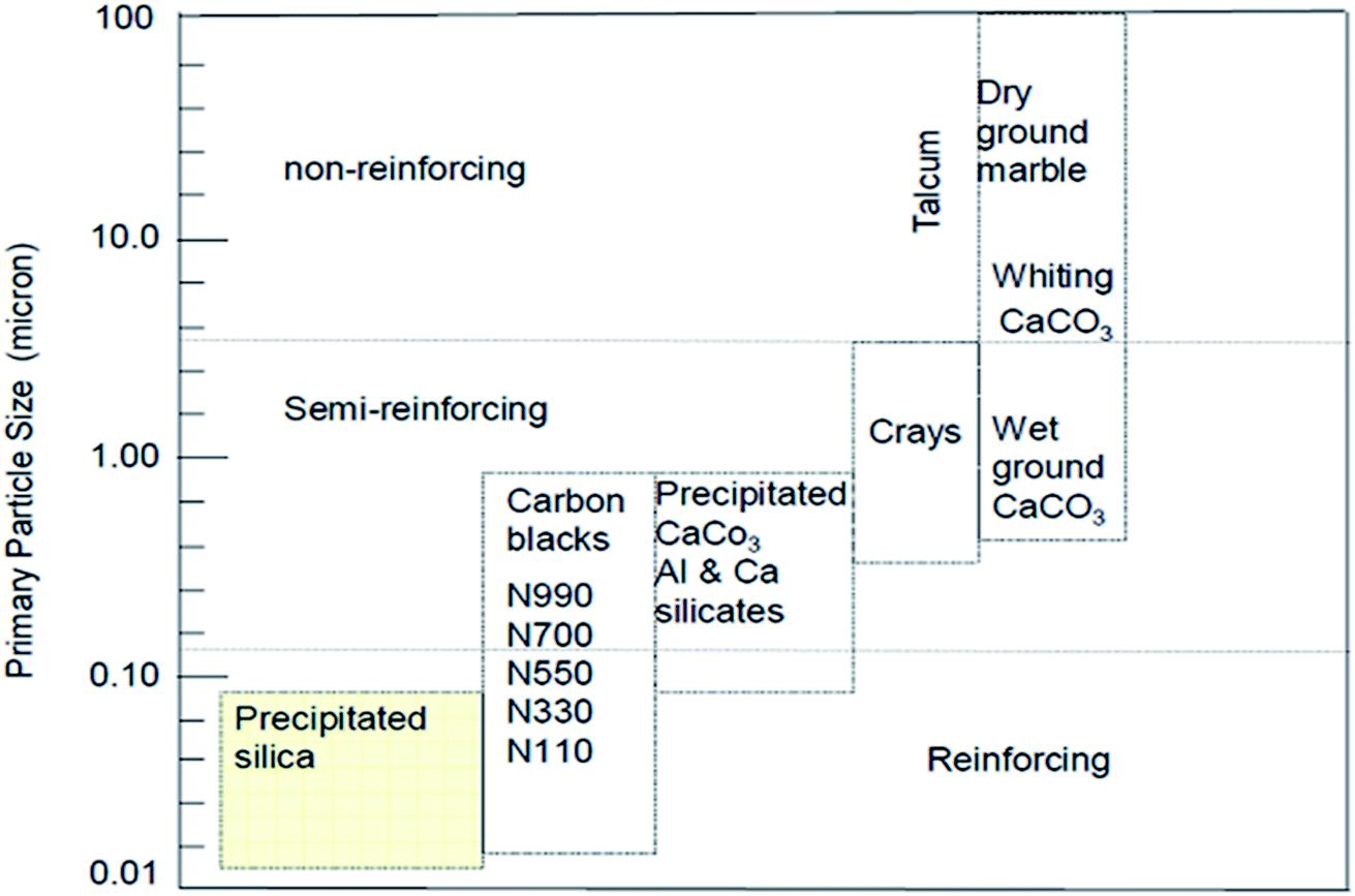
Bulky particulate materials like calcium carbonate can be employed just to reduce the cost of the final material without any improvement of properties. In this case, they can be simply called extenders or non-reinforcing fillers. On the other hand, there are fillers like precipitated silica, as observed in Fig. 7, with a reduced nano size scale, which can reinforce the rubber, known as active fillers.33
 | ||
| Fig. 7 Classifications of filler reinforcing effect according to the particle size.33 | ||
![[triple bond, length as m-dash]](https://www.rsc.org/images/entities/char_e002.gif) Si–OH) and siloxane groups are generated on the surface of the particles. The surface is mainly characterized by the (i) number of silanol groups, (ii) degree of hydration, (iii) amount of adsorbed water, and (iv) its surface acidity. The silanols are classified into three categories depending on the precipitation conditions shown in Fig. 8.86,88
Si–OH) and siloxane groups are generated on the surface of the particles. The surface is mainly characterized by the (i) number of silanol groups, (ii) degree of hydration, (iii) amount of adsorbed water, and (iv) its surface acidity. The silanols are classified into three categories depending on the precipitation conditions shown in Fig. 8.86,88
 | ||
| Fig. 8 Types of silanol groups on the SiO2 surface.86,88 | ||
These groups display a strong affinity for water molecules, especially the geminal type of silanol groups. In HD SiO2, the germinal content is less than 20%. Silanol groups on the silica surface also improve the bond ability of new rubber compounds with older rubber, e.g., retread compound with old rubber. The polar component of SiO2 is relatively high due to the presence of a large number of polar groups on the filler surface and the difference in the solubility parameters of the polymers and the filler is responsible for the degree of wetting of fillers by polymers.89,90 The Hildebrand solubility parameters of some polymers and silica are shown in Table 6.84
| Polymer material | Hildebrand solubility parameter (MPa1/2) |
|---|---|
| NBR | 19.3–20.3 |
| SBR | 16.6–18.3 |
| NR, BR, IIR | 16.2–16.6 |
| PE, EPM, EPDM | 16.2 |
| Silica | 28.4–36.5 |
| Carbon black | 24.4–30.5 |
From Table 7, it may be seen that in comparison to the polymers listed and carbon black, the high solubility parameter of SiO2 leads to difficulty in blending SiO2 fillers with polymers. Based on the studies of the interactions of SiO2 surfaces with low molecular weight analogs of elastomers, the level of interaction has been classified as:89
| NBR > SBR > NR ≥ BR > HV-BR > EPR > IIR |
| SiO2/CB in parts per hundred (phr) | |||||
|---|---|---|---|---|---|
| Testing items | 0/70 | 20/50 | 35/35 | 50/20 | 70/0 |
| t10 (min) | 5 | 4.2 | 4.4 | 4.3 | 4.5 |
| t90 (min) | 8.3 | 8.2 | 9.2 | 11 | 17.1 |
| Shore A hardness | 68 | 68 | 65 | 65 | 64 |
| Modulus at 300% (MPa) | 11.6 | 18.3 | 15.6 | 15.1 | 12.8 |
| Tensile strength (MPa) | 17.3 | 22.8 | 22.2 | 21.5 | 20.3 |
| Elongation at break (%) | 356 | 378 | 409 | 454 | 402 |
| Tear strength (kNm−1) | 46.6 | 48.1 | 57.9 | 50.7 | 46.9 |
| Dynamic compression heat buildup (°C) | 20.1 | 16.9 | 16.7 | 15.5 | 10.7 |
3.2. Bound rubber model of SiO2-filled rubber
During the processing of SiO2-filled rubbers, various chemical reactions occur, and generally, there exist two components: (i) occluded rubber in SiO2 aggregates and (ii) cross linked polymer due to polymer chain scission and recoupling reactions. These two phenomena are responsible for the bound rubber of SiO2-filled rubber91 and a model of the SiO2/silane reinforcement based on the hydrodynamic–occlusion–interaction theory86,92,93 is shown in Fig. 9.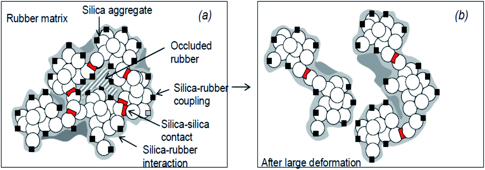 | ||
| Fig. 9 Model of the silica/silane reinforcement (a): no deformation; (b): after large deformation.93 | ||
The large polarity difference between the SiO2 filler and the rubber matrix leads to the ease of formation of a filler–filler network, with part of the matrix occluded in the filler network. This occluded rubber is both physically and chemically immobilized within the filler network. Under high deformation, the filler network partially breaks down, and with the increase in deformation of the rubber, the occluded rubber within the filler network reduces, followed by a deformation of the matrix. Due to the chemical bonding via a silane coupling agent, the occluded rubber and rubber on the SiO2 surface remain immobilized and still contribute to the modulus even at high deformations. The chemically immobilized rubber is the in-rubber structure.
The mechanisms of components of bound rubbers directly contacted to silica surface are in terms of multiple contact rubber chain, insert rubber chain, chemically bonded rubber chain, and single contact rubber chain, as shown in Fig. 10.94
 | ||
| Fig. 10 Components of bound rubbers directly in contact with the silica surface. (a) Multiple contact rubber chain, (b) insert rubber chain, (c) chemically bonded rubber chain, and (d) single contact rubber chain.94 | ||
3.3. Effects of filler–filler and SiO2 filler–rubber interactions
The filler–rubber interaction depends on the particle size and shape, surface characteristics of the filler, as well as the chemical nature of the polymer. It increases with the filler dispersion and with the extent of the organic/inorganic interface. Many studies have also demonstrated that the filler-rubber interaction induces the formation of a polymer layer around filler particles (the so-called bound rubber) with a consequent slowdown of the dynamics of the rubber chains interacting with the particle surface. The stronger the interaction, the more tied the polymer layer.95 Filler–filler interaction is due to the strong tendency of silica particles embedded in rubber to interact with each other by surface silanol condensation. This favors a strong inter-particle aggregation, which contrasts the filler–rubber interaction and lowers the homogeneous distribution of the filler. This drawback can be ridden out by using suitable coupling agents (e.g., silanes), which form chemical bonds between the polymer chains and the oxide, improving the compatibility with the rubber matrix.96The control of both filler–filler and filler–rubber interactions plays a key role in determining the filler reinforcing action. In fact, the reinforcement due to filler–rubber interaction is almost independent of the strain amplitude. On the other hand, the filler–filler interaction enhances the modulus at low strain, but breakdowns at high strain. This causes a drop in the modulus (Payne effect), which is associated with an energy dissipative process and Mullen's effect as well.97
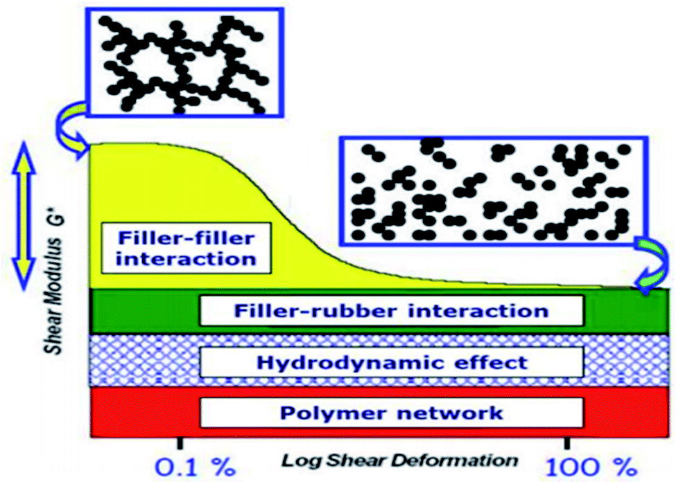 | ||
| Fig. 11 Stress–strain curve of SiO2 filled rubber nanocomposite: strain-dependent and strain independent contributions to the Payne effect are differently colored.99 | ||
The vulcanized nanocomposites of diverse compositions demonstrate the Payne effect and weak overshoot behavior being dominated by the viscoelastic deformation of the rubber matrix with defective crosslinking network. The filler amplifies the microscopic strain of the matrix, which is more significant for the silicious than the carbonaceous fillers. While both the silicious and carbonaceous fillers tend to lower the intensities of the weak overshoot, and the serious agglomeration of silica may cause interparticle friction to intensify the overshoot at high filler loadings. On the other hand, the interaction between silica and rubber based on covalent bonding from silanization tends to intensify the strain amplification effect and filler–rubber interfacial friction. Payne effect at small strain shear deformation and other strain independent contributions (strong filler–rubber interaction) on reinforcement degree of rubber by SiO2 filler can be reduced by surface modification of either the filler or polymer due to covalent bonds existing at the polymer–particle interface (through coupling agents), and in the in-rubber structure (sulfur crosslinks).98
Besides the tensile test, it is possible to evaluate the energy losses localized at different strain intervals, allowing the material to restore between one cycle and the other, separating permanent (purely viscous) losses from reversible (viscoelastic) losses with the hysteresis measured in each cycle considered as an indicator of these losses.100 The dissipative effect at different strain levels has been related to different physical phenomena, as shown in Fig. 12.33,101
 | ||
| Fig. 12 Different dissipative mechanisms associated to the Mullins effect.33,101 | ||
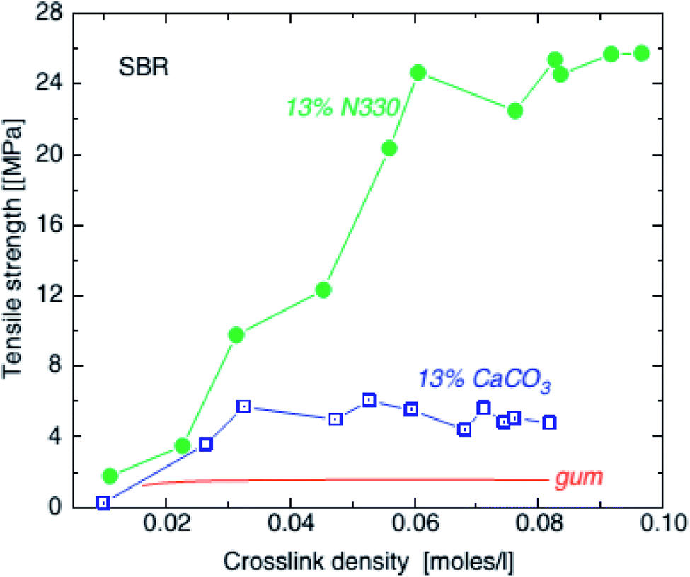 | ||
| Fig. 13 Tensile strength of SBR unfilled (line), with 0.13 volume fraction (45 phr) calcium carbonate (squares) and with 0.13 volume fraction (30 phr) HAF carbon black and precipitated SiO2, as a function of crosslink density.102 | ||
The mechanical properties of SSBR composites filled with SiO2/CB exhibited a ‘‘synergistic effect.’’ Among these, the composite with SiO2/CB (20/50) showed good filler dispersion with low heat generation, as shown in Table 7.103
3.4. Overcoming difficulties in the use of SiO2 fillers
Mixing SiO2 filler into rubber is a challenge. The dispersive part, a component of surface free energy, is low, i.e., weak interaction between the filler particles and rubber, resulting in a low reinforcing effect. However, the specific part, the second component of surface free energy, is high, i.e., a strong filler–filler interaction leading to a substantial increase in the viscosity of SiO2–rubber compounds. The interparticle forces between filler particles must be overcome during mixing so that a satisfactory dispersion of filler particles can take place and a link between the SiO2 particles and rubber may be established. For a homogeneous distribution of filler aggregates within a matrix, intensive contact between filler particles and rubber is a necessary criterion for efficient mixing. The two most important characteristics that determine the contact between the surface of the filler and the rubber matrix are the surface area of the filler and its wettability.104,105Wettability is significant when using SiO2 fillers as there exists a mismatch between the solubility parameters of the polar SiO2 filler and nonpolar rubber. This mismatch affects both its compatibility with non-polar elastomers and the cure characteristics of the compounds. The high structure of SiO2 filler (aggregates and agglomerates) is characterized by a high surface area and a high percentage of the void volume within the structure. Since a direct interaction between the filler and polymer is low, polymer chains are physically entrapped in the voids of the filler structure. To enhance the polymer–SiO2 filler interaction, the filled structure has to be broken to an optimum level during mixing.106
From an industrial perspective, it has been observed that reinforcing by carbon black was more efficient than SiO2 until silane coupling agents were introduced to reduce the polarity differences between the polar filler and nonpolar rubbers. These agents are able to react with both the SiO2 surface and the polymer forming a chemical linkage between the filler particles and rubber, thus overcoming the problems of both increased viscosity and dispersion. The result is the enhancement of the properties of the final product.107 They may be premixed or pre-reacted with the SiO2 particles or may be added to the rubber mix during mixing with consideration that the coupling agents then combine in situ with SiO2.108
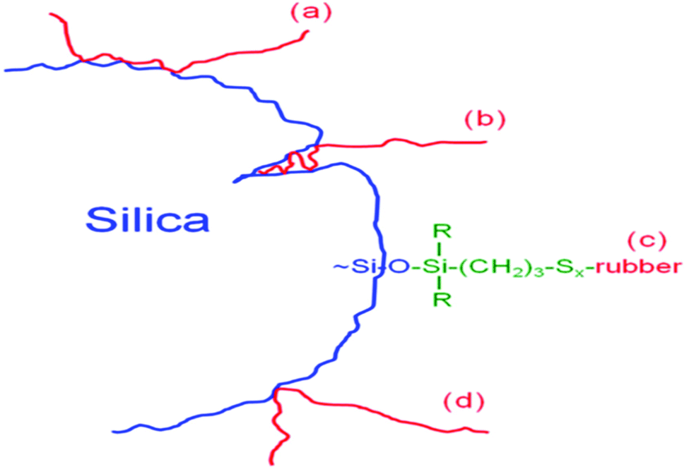
Different types of coupling agents have been developed over the years to improve the compatibility and dispersion of SiO2 fillers in different polymer matrices. Some commonly used silane coupling agents include, e.g., bis(triethoxysilylpropyl) tetrasulfide (TESPT): the polysulfide part of which reacts with the polymer, and the ethoxysilyl groups on the silicon atom react with the hydroxyl groups present on the surface of SiO2.109 The average sulfur rank of the polysulfide is 3.86 and is unstable at high shear or high temperature. During rubber processing, the TESPT molecules split and release reactive sulfur moieties in the compounds, thus performing as a sulfur donor.110,111
Another silane that releases sulfur during processing is bis (triethoxysilylpropyl) disulfide (TESPD: Si266/Si75), which comprises mixtures of polysulfides and has an average sulfur rank close to 2. This silane is more stable at high shear or high temperatures compared to TESPT, and therefore, rubber compounds are less sensitive to scorch. But, due to its lower sulfur content, additional elemental sulfur needs to be incorporated into rubber to achieve comparable reinforcement to TESPT.92,112
There are also other types of silane coupling agents commercially available and are used based on the type of the polymer matrix and target application of the SiO2–rubber compound. They are used to reduce the emission of volatile organic compounds such as ethanol during the mixing process or product lifetime, e.g., tires.113–118
The reaction mechanism of silanization is exemplified by that of TESPT in Fig. 14(a) and (b). In the primary step, the reaction of the first alkoxy group of the silane with silanol groups on the SiO2 surface takes place via two possible mechanisms (Fig. 14(a)): a direct reaction of the silanol groups on the silicon with the alkoxy group of TESPT and hydrolysis of the alkoxy group to form a reactive silanol with the release of ethanol.
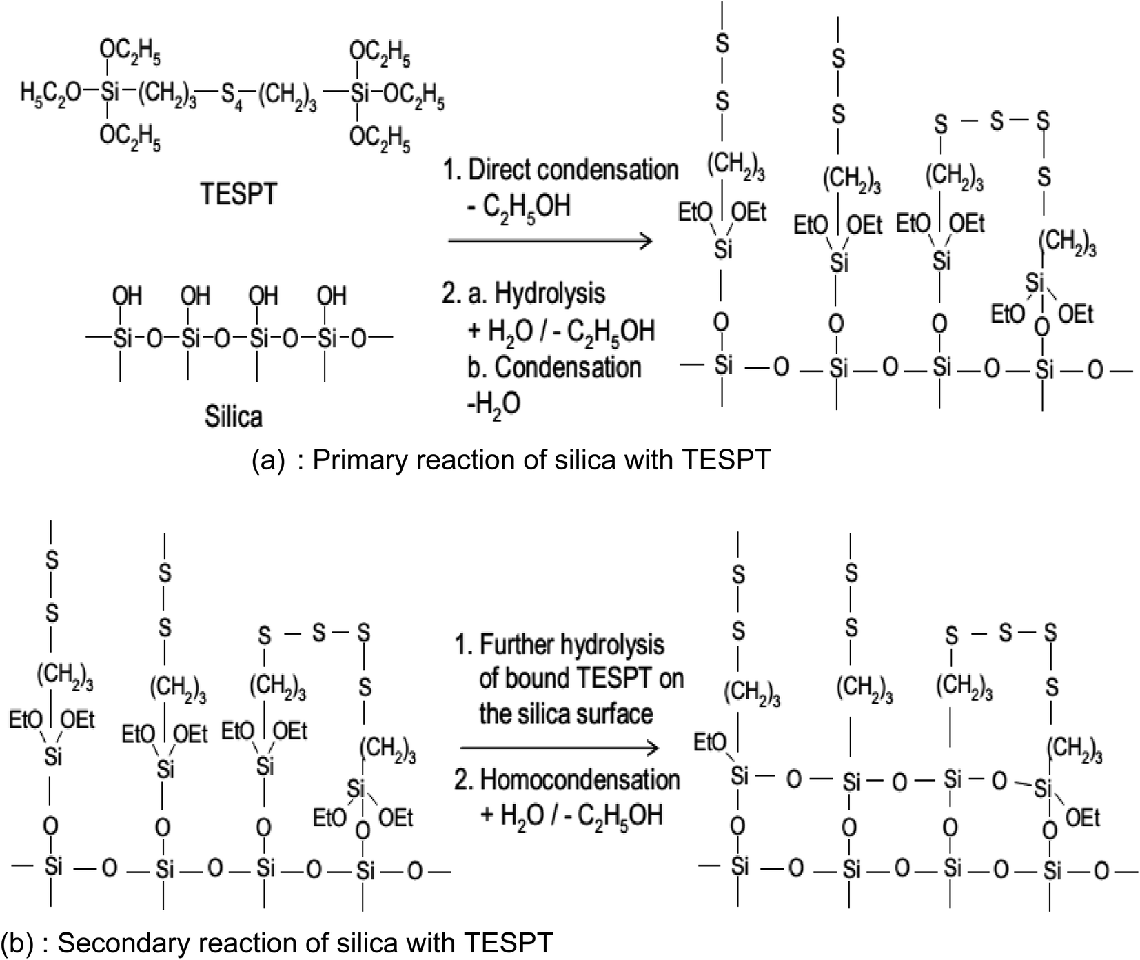 | ||
| Fig. 14 Reaction mechanism of silanization.92 | ||
These reactions occur slowly on the SiO2 surface in the presence of water.119 The rate constant of hydrolysis increases with increasing temperature in the presence of a catalytic agent such as an acidic or alkaline medium. Post hydrolysis, the activated silane is capable of reacting with silanol groups on SiO2. The rate constant of this reaction is relatively faster than hydrolysis, i.e., the hydrolysis reaction is the rate determining step for silanization.114 Just after the primary reaction, a secondary reaction (Fig. 14(b)), and an intermolecular condensation between the silanes on the SiO2 surface caused by the unreacted ethoxy groups of the silanes occur. The rate of reaction is, however, slower than the primary reaction and may be accelerated by water accompanied by an increase in temperature. For an optimal level of reinforcement, it is preferred to have a low degree of intermolecular condensation.91,120
The degree of silanization can be significantly improved and accelerated by 1,3-diphenylguanidine (DPG) or by accelerators such as amines, enamines (–RC = C–NR2), and aldimines (R–CH = N–R) in combination with DPG.121,122
4. Summary and future recommendations
The search for nonpetroleum-based fillers, which are environmentally friendly, cheap, abundant, and renewable, has been raised nowadays. Literature reports published so far evidenced the improving physicochemical properties of nanostructured SiO2 and reduction of the cost of production by searching for potential precursors, and low energy consuming methods is an important research area. The main bottleneck problem for the application of sol–gel processes at a larger scale is the use of expensive alkoxide precursors in the liquid state. Therefore, in the near future, alternative precursors from local materials are an urgent call to researchers.Other parameters that play a crucial role in the performance of rubber materials are size, surface chemistry, surface area, and aspect ratio of nanofillers. Owing to their large availability, low cost, high surface area, green and possible sol–gel preparation from sodium silicate precursors, nowadays, nanosilica structures with different physicochemical characteristics and aspect ratios have attracted huge interest as reinforcing agents for rubber materials. Despite the fact that rare studies have been conducted so far on the effect of nanosilica structure on rubber nanocomposites, a larger scope exists in the development of novel rubber products using different nanostructures of silica synthesized from natural sources, i.e., biogenic and mineral ore resources.
Nanofillers, particularly anisotropic silica, show great promising results, and their commercial potential is significant. However, the dispersion problem of SiO2 nanostructures, encountered in the use of all reinforcing fillers, remains a major obstacle to the utilization of nanoparticles in the rubber industry. Recent works showed that the surface modification of silica with silane coupling agent made it competitively applied to rubber industries. Recently, researchers tried some investigations on the effect of anisotropic silica on rubber reinforcement, Payne and Mullen's effects reduction, and parameter optimized sol–gel synthesized spherical and rode shaped silica becomes a promoted rubber reinforcement filler but very rarely investigated yet. Therefore further studies in all aspects of nanostructured SiO2 material for rubber reinforcement efficiency is a hot research area of study.
Conflicts of interest
The authors declared that they have no conflict of interest.Acknowledgements
The authors greatly acknowledge Assosa University and Adama Science and Technology University, Ethiopia.References
- International Standards Organization (ISO), Nanotechnology – Terminology and definitions for nanoparticles, Geneva, Switzerland, 2007 Search PubMed
.
- Y. Zhang, X. Qian, Ã. Z. Li, J. Yin and Z. Zhu, Synthesis of novel mesoporous silica spheres with starburst pore canal structure, J. Mater. Chem., 2004, 177, 844–848 CAS
- ECETOC 2006, European Centre for Ecotoxicology and Toxicology, “Synthetic amorphous silica (CAS no. 7631-86-9), JACC report no. 51,” no. 7631, 2006 Search PubMed
- W. K. Dierkes, Economic Mixing of Silica–Rubber Compounds, PhD thesis, University of Twente, Enschede, the Netherlands, 2005
- K. Song, et al., Structural Polymer-Based Carbon Nanotube Composite Fibers: Understanding the Processing–Structure–Performance Relationship, Adv. Colloid Interface Sci., 2013, 2543–2577 Search PubMed
- R. Sengupta, et al., A Short Review on Rubber/Clay Nanocomposites With Emphasis on Mechanical Properties, Appl. Surf. Sci., 2007, 21–25 Search PubMed
- G. Sui, W. H. Zhong, X. P. Yang, Y. H. Yu and S. H. Zhao, Preparation and properties of natural rubber composites reinforced with pretreated carbon nanotubes, J. Elastomers Plast., 2008, 1543–1549 CAS
- C. Zhang, et al., Concurrently improved dispersion and interfacial interaction in rubber/nanosilica composites via efficient hydrosilane functionalization. Composites Science and Technology, J. Elastomers Plast., 2019, 169, 217–223 CAS
- A. Snchez-Ferrer, M. Reufer, R. Mezzenga, P. Schurtenberger and H. Dietsch, Inorganic–organic elastomer nanocomposites from integrated ellipsoidal silica-coated hematite nanoparticles as crosslinking agents, Nanotechnology, 2010, 21(18), 185603 CrossRef PubMed
- J.-Y. Kwon, et al., Transparent Amorphous Oxide Semiconductor Thin Film Transistor, Electronic Mater. Lett., 2011, 7(1), 1–11 CrossRef CAS
- K. M. Kim, S. J. Song, G. H. Kim, J. Y. Seok, M. H. Lee and J. H. Yoon, Collective Motion of Conducting Filaments in Pt/n-Type TiO2/p-Type NiO/Pt Stacked Resistance Switching Memory, Adv. Funct. Mater., 2011, 21, 1587–1592 CrossRef CAS
- N. Shimura and M. Ogava, Growth of nanoporous silica spherical particles by the stober method combined with supramolecular templating approach, Bull. Chem. Soc. Jpn., 2005, 78, 1154–115960 CrossRef CAS
- B. Tan, H. J. Lehmler, S. M. Vyas, B. L. Knutson and S. E. Rankin, Controlling nanopore size and shape by fluorosurfactant templating of silica, Chem. Mater., 2005, 17(4), 916–925 CrossRef CAS
- B. Tan and S. E. Rankin, Interfacial alignment mechanism of forming spherical silica with radially oriented nanopores, J. Phys. Chem. B, 2004, 108(52), 20122–20129 CrossRef CAS
- O. I. Lebedev, G. V. Tendeloo, C. O. Collart and P. E. F. Vansant, Structure and microstructure of nanoscale mesoporous silica spheres, Solid State Sci., 2004, 6, 489–498 CrossRef CAS
- Y. Zhang, X. Qian, Ã. Z. Li, J. Yin and Z. Zhu, Synthesis of novel mesoporous silica spheres with starburst pore canal structure, J. Macromol. Sci., Part B: Phys., 2004, 177, 844–848 CAS
- I. J. Fernandes, et al., Characterization of silica produced from rice husk ash: comparison of purification and processing methods, Mater. Res., 2017, 20, 519–525 CrossRef
- N. Awaji, et al., Thermal oxide growth at chemical vapor deposited SiO2/Si interface during annealing evaluated by difference X-ray reflectivity Thermal oxide growth at chemical vapor deposited SiO2/Si interface during annealing evaluated by difference X-ray reflectivity, RSC Adv., 2003, 1954, 65–68 Search PubMed
- N. Baccile, D. Grosso, M. Curie, P. Vi, P. Jussieu and T. P. Cedex, Aerosol generated mesoporous silica particles, Nanomaterials, 2003, 3011–3016 CAS
- C. R. Miller, R. Vogel, P. P. T. Surawski, K. S. Jack, S. R. Corrie and M. Trau, Functionalized organosilica microspheres via a novel emulsion-based route, Langmuir, 2005, 21(21), 9733–9740 CrossRef CAS PubMed
- Y. S. Cho, G. R. Yi, S. H. Kim, D. J. Pine and S. M. Yang, Colloidal clusters of microspheres from water-in-oil emulsions, Chem. Mater., 2005, 17(20), 5006–5013 CrossRef CAS
- K. D. S. C. T. Chu, D. H. O. E. W. Sheppard, J. B. Higgins and J. L. Schlenker, A New Family of Mesoporous Molecular Sieves Prepared with Liquid Crystal Templates, Springer, 1992, vol. 14, pp. 10834–10843 Search PubMed
- R. Narayan, U. Y. Nayak, A. M. Raichur and S. Garg, Mesoporous silica nanoparticles: a comprehensive review on synthesis and recent advances, Pharmaceutics, 2018, 10(3), 1–49 CrossRef PubMed
- N. K. Raman, M. T. Anderson and C. J. Brinker, Template-based approaches to the preparation of amorphous, nanoporous silicas, Chem. Mater., 1996, 8(8), 1682–1701 CrossRef CAS
- J.-Y. Zheng, J.-B. Pang, K.-Y. Qiu and W. Yen, Synthesis of mesoporous titanium dioxide materials by using a mixture of organic compounds as a non-surfactant template, J. Mater. Chem., 2001, 11, 3367–3372 RSC
- G. Larsen, E. Lotero and M. Marquez, Amine Dendrimers as Templates for Amorphous Silicas, J. Phys. Chem. B, 2000, 104(20), 4840–4843 CrossRef CAS
- I. Muylaert, A. Verberckmoes, J. De Decker and P. Van Der Voort, Ordered mesoporous phenolic resins: highly versatile and ultra stable support materials, Adv. Colloid Interface Sci., 2012, 175, 39–51 CrossRef CAS PubMed
- N. Pal and A. Bhaumik, Soft templating strategies for the synthesis of mesoporous materials: inorganic, organic-inorganic hybrid and purely organic solids, Adv. Colloid Interface Sci., 2013, 189–190, 21–41 CrossRef CAS PubMed
- P. Alexandridis, U. Olsson and B. Lindman, Self-Assembly of Amphiphilic Block Copolymers: The(EO)13(PO)30(EO)13–Water–p-Xylene System, Macromolecules, 1995, 28(23), 7700–7710 CrossRef CAS
- L. C. Vaz, Determination of the Critical Micelle Concentration of Surfactants the Fluorescent Probe N-Phenyl-I-naphthylamine, Chem. Mater., 1986, 255, 250–255 Search PubMed
- G. J. D. A. A. Soler-Illia, C. Sanchez, B. Lebeau and J. Patarin, Chemical strategies to design textured materials: From microporous and mesoporous oxides to nanonetworks and hierarchical structures, Chem. Rev., 2002, 102(11), 4093–4138 CrossRef PubMed
- T. Asefa, M. J. MacLachlan, N. Coombs and G. A. Ozin, Periodic mesoporous organosilicas with organic groups inside the channel walls, Nature, 1999, 402(6764), 867–871 CrossRef CAS
- L. Tadiello, Role of the silica nanoparticle anisotropy on morphological and mechanical properties of Styrene Butadiene Rubber nanocomposites, PhD thesis, University of Milan – Bicocca, 2015
- C. Jeffrey Brinker, N. K. Raman and M. T. Anderson, Template-Based Approaches to the Preparation of Amorphous, Nanoporous Silicas, Chem. Mater., 1996, 8, 1682–1701 CrossRef
- A. Berggren, A. E. C. Palmqvist and K. Holmberg, Surfactant-templated mesostructured materials from inorganic silica, Soft Matter, 2005, 1(3), 219–226 RSC
- Y. Wan and D. Zhao, On the controllable soft-templating approach to mesoporous silicates, Chem. Rev., 2007, 107(7), 2821–2860 CrossRef CAS PubMed
- Malgras, H. Ataee-Esfahani, H. Wang, B. Jiang, C. Li, K. C.-W. Wu, J. H. Kim and Y. Yamauchi, Nanoarchitectures for Mesoporous Metals, Adv. Mater., 2016, 28, 993–1010 CrossRef CAS PubMed
- H. El-Didamony, E. El-Fadaly, A. A. Amer and I. H. Abazeed, Synthesis and characterization of low cost nanosilica from sodium silicate solution and their applications in ceramic engobes, Bol. Soc. Esp. Ceram. Vidrio, 2019, 1–13 Search PubMed
- M. Eneng, S. Rifki and Suhanda, Effects of the precipitation ph of sodium silicate on the amorphous silica characteristics and its capability in the Pb and Cd adsorption, Res. J. Chem. Environ., 2018, 22, 172–178 Search PubMed
- D. R. Mujiyanti, M. D. Surianthy and A. B. Junaidi, The Initial Characterization of Nanosilica from Tetraethylorthosilicate (TEOS) with the Addition Polivynil Alcohol by Fourier Transform Infra Red, IOP Conf. Ser. Earth Environ. Sci., 2018, 187, 012056 CrossRef
- N. X. Huan, et al., Nanosilica synthesis and application for lead treatment in water, Chem. Soc. Rev., 2018, 9(5), 255–263 Search PubMed
- F. Reactor, M. Development and C. Division, Influence of pH on the Spherical Shape and Particle Size of the Freeze Drying Assisted Sol-gel Derived Silica Nano-Particles (SNPs), Chem. Commun., 2017, 1, 2347–2353 Search PubMed
- Q. Zhu, H. Lei Zhou, Y. Xiao Song, Z. Dong Chang and W. Jun Li, Modification and investigation of silica particles as a foam stabilizer, Int. J. Miner., Metall. Mater., 2017, 24(2), 208–215 CrossRef CAS
- N. I. Vazquez, Z. Gonzalez, B. Ferrari and Y. Castro, Synthesis of mesoporous silica nanoparticles by sol-gel as nanocontainer for future drug delivery applications, Bol. Soc. Esp. Ceram. Vidrio, 2017, 56(3), 139–145 CrossRef CAS
- H. N. Azlina, J. N. Hasnidawani, H. Norita and S. N. Surip, Synthesis of SiO2 nanostructures using sol-gel method, Acta Phys. Pol., A, 2016, 129(4), 842–844 CrossRef CAS
- M. H. Al-maamori, J. K. Ahmed and H. M. Ali, Production of Nano-Silica from Water Glass Production of Nano-Silica from Water Glass, Acad. Res. Int., 2016, 1–9 Search PubMed
- Y. He, H. Xu, S. Ma, P. Zhang, W. Huang and M. Kong, Fabrication of mesoporous spherical silica nanoparticles and effects of synthesis conditions on particle mesostructure, Mater. Lett., 2014, 131, 361–365 CrossRef CAS
- A. R. Maurice and H. Faouzi, Synthesis and Characterization of Amorphous Silica Nanoparticles from Aqueous Silicates Using Cationic Surfactants, J. Met., Mater. Miner., 2014, 24(1), 37–42 Search PubMed
- L. P. Singh, S. K. Bhattacharyya, G. Mishra and S. Ahalawat, Functional role of cationic surfactant to control the nano size of silica powder, Appl. Nanosci., 2011, 1(3), 117–122 CrossRef CAS
- L. P. Singh, S. K. Agarwal, S. K. Bhattacharyya, U. Sharma and S. Ahalawat, Preparation of silica nanoparticles and its beneficial role in cementitious materials, Nanomater. Nanotechnol., 2011, 1(1), 44–51 CAS
- S. Musić, N. Filipović-Vinceković and L. Sekovanić, Precipitation of amorphous SiO2 particles and their properties, Braz. J. Chem. Eng., 2011, 28(1), 89–94 CrossRef
- M. A. El-Sayed and T. M. El-Samni, Physical and Chemical Properties of Rice Straw Ash and Its Effect on the Cement Paste Produced from Different Cement Types, J. King Saud Univ., Eng. Sci., 2006, 19(1), 21–29 Search PubMed
- M. Estevez, S. Vargas, V. M. Castaño and R. Rodriguez, Silica nano-particles produced by worms through a bio-digestion process of rice husk, J. Non-Cryst. Solids, 2009, 355(14–15), 844–850 CrossRef CAS
- FAO RMM 2018, Food and Agriculture Organization of the United Nations, Rice Market Monitor (FAO, RMM), 2018, p. 37 Search PubMed
- P. K. Jal, M. Sudarshan, A. Saha, S. Patel and B. K. Mishra, Synthesis and characterization of nanosilica prepared by precipitation method, Colloids Surf., A, 2004, 240(1–3), 173–178 CrossRef CAS
- T. Witoon, M. Chareonpanich and J. Limtrakul, Synthesis of bimodal porous silica from rice husk ash via sol-gel process using chitosan as template, Mater. Lett., 2008, 62(10–11), 1476–1479 CrossRef CAS
- N. Yalçin and V. Sevinç, Studies on silica obtained from rice husk, Ceram. Int., 2001, 27(2), 219–224 CrossRef
- I. A. Rahman, J. Ismail and H. Osman, Effect of nitric acid digestion on organic materials and silica in rice husk, J. Mater. Chem., 1997, 7(8), 1505–1509 RSC
- S. Rungrodnimitchai and W. Phokhanusai, Preparation of Silica Gel from Rice Husk Ash Using Microwave Heating Preparation of Silica Gel from Rice Husk Ash Using Microwave Heating, J. Met., Mater. Miner., 2015, 19, 45–50 Search PubMed
- S. Huang, S. Jing, J. Wang, Z. Wang and Y. Jin, Silica white obtained from rice husk in a fluidized bed, John Wiley & Sons, 2001, pp. 232–238 Search PubMed
- J. Umeda and K. Kondoh, High-purity amorphous silica originated in rice husks via carboxylic acid leaching process, J. Mater. Sci., 2008, 43(22), 7084–7090 CrossRef CAS
- P. S. Utama, R. Yamsaengsung and C. Sangwichien, Production and Characterization of Precipitated Silica From Palm Oil Mill Fly Ash Using Co2 Impregnation and Mechanical Fragmentation, Braz. J. Chem. Eng., 2019, 36(1), 523–530 CrossRef CAS
- E. Akhayere, D. Kavaz and A. Vaseashta, Synthesizing nano silica nanoparticles from barley grain waste: effect of temperature on mechanical properties, Pol. J. Environ. Stud., 2019, 28(4), 2513–2521 CrossRef
- S. Rovani, J. J. Santos, P. Corio and D. A. Fungaro, Highly Pure Silica Nanoparticles with High Adsorption Capacity Obtained from Sugarcane Waste Ash, ACS Omega, 2018, 3(3), 2618–2627 CrossRef CAS PubMed
- D. F. Hincapié-Rojas, A. Rosales-Rivera and P. Pineda-Gomez, Synthesis and characterization of submicron silica particles from rice husk, Green Mater., 2018, 6(1), 15–22 CrossRef
- S. L. Qi, W. S. Cui and Z. N. M. Du, Hydrophobic silica aerogel derived from wheat husk ash by ambient pressure drying, J. Sol-Gel Sci. Technol., 2015, 1–8 Search PubMed
- M. E. C. Washington LE, Preparation and Characterization of Nano Silica from Equisetum arvenses, J. Bioprocess. Biotech., 2015, 5(2), 205 Search PubMed
- A. B. Bageru and V. C. Srivastava, Efficient teff-straw based biocomposites with chitosan and alginate for pyridine removal, Int. J. Environ. Sci. Technol., 2018, 0123456789 Search PubMed
- F. D. M. Daud, M. H. Johari, A. H. A. Jamal, N. A. Z. Kahlib and A. L. Hairin, Preparation of nano-silica powder from silica sand via sol-precipitation method, AIP Conf. Proc., 2019, 2068, 1–5 Search PubMed
- S. Stopic, et al., Synthesis of Nanosilica via Olivine Mineral Carbonation under High Pressure in an Autoclave, Metals, 2019, 9(6), 708 CrossRef CAS
- R. Dewati, S. Suprihatin, K. Sumada, S. Muljani, M. Familya and S. Ariani, Precipitated Silica from Pumice and Carbon Dioxide Gas (CO2) in Bubble Column Reactor, J. Phys.: Conf. Ser., 2018, 953(1), 012226 CrossRef
- N. Raza, W. Raza, S. Madeddu, H. Agbe, R. V. Kumar and K. H. Kim, Synthesis and characterization of amorphous precipitated silica from alkaline dissolution of olivine, RSC Adv., 2018, 8(57), 32651–32658 RSC
- E. R. Essien, O. A. Olaniyi, L. A. Adams and R. O. Shaibu, Sol-Gel-Derived Porous Silica:Economic Synthesis and Characterization, J. Miner. Mater. Charact. Eng., 2011, 11(10), 1–6 Search PubMed
- N. D. V. Quang and L. D. Vuong, Alexandrov OV and Bulgakov BI Synthesis and characterization of silica nanoparticles from Vietnam, Nanomater. Energy, 2019, 8, 1–5 CrossRef
- A. Mourhly, F. Jhilal, A. El Hamidi, M. Halim and S. Arsalane, Highly efficient production of mesoporous nano-silica from unconventional resource: process optimization using a Central, J. Compos. Mater., 2019, 145, 139–145 CAS
- R. Sharafudeen, J. M. Al-Hashim, M. O. Al-Harbi, A. I. Al-Ajwad and A. A. Al-Waheed, Preparation and Characterization of Precipitated Silica using Sodium Silicate Prepared from Saudi Arabian Desert Sand, Silicon, 2017, 9(6), 917–922 CrossRef CAS
- K. Lazaar, W. Hajjaji, R. C. Pullar, J. A. Labrincha, F. Rocha and F. Jamoussi, Production of silica gel from Tunisian sands and its adsorptive properties, J. Afr. Earth Sci., 2017, 130, 238–251 CrossRef CAS
- M. Sarikaya, T. Depci, R. Aydogmus, A. Yucel and N. Kizilkaya, Production of Nano Amorphous SiO2 from Malatya Pyrophyllite, IOP Conf. Ser. Earth Environ. Sci., 2016, 44(5), 052004 CrossRef
- A. Mourhly, M. Khachani, A. El Hamidi, M. Kacimi, M. Halim and S. Arsalane, The Synthesis and Characterization of Low-Cost Mesoporous Silica SiO2 from Local Pumice Rock, Nanomater. Nanotechnol., 2015, 5, 35 CrossRef
- K. Srivastava, N. Shringi, V. Devra and A. Rani, Pure Silica Extraction From Perlite: Its Characterization And Affecting Factors, Int. J. Innov. Res. Sci. Eng. Technol., 2013, 2(7), 2936–2942 Search PubMed
- A. Blume, Analytical properties of silica: a key for understanding silica reinforcement, Kautsch. Gummi Kunstst., 2000, 53(6), 338–345 CAS
- T. I. Project, Reinforcing Fillers in the Rubber Industry: Assessment as Potential Nanomaterials with a Focus on Tires, 2011 Search PubMed
- J. W. Ten Brinke, P. J. Van Swaaij, L. A. E. M. Reuvekamp and J. W. M. Noordermeer, Reactive mixing of silica and rubber for tyres and engine mounts: influence of dispersion morphology on dynamic mechanical properties, PhD thesis, Twente University Press (TUP), Enschede, The Netherlands, 2003
- R. F. Grossman, The Mixing of Rubber, Chapman & Hall, 1997, p. 25 Search PubMed
- M. P. Wagner, Reinforcing Silicas and Silicates, Rubber Chem. Technol., 1976, 49(3), 703–774 CrossRef CAS
- J. Janzen and G. Kraus, Specific Surface Area Measurements on Carbon Black, Rubber Chem. Technol., 1971, 44(5), 1287–1296 CrossRef CAS
- A. Voet, J. C. Morawski and J. B. Donnet, Rubber Chem. Technol., 1971, 50, 342 CrossRef
- J. L. Leblanc, Rubber ±filler interactions and rheological properties in filled compounds, 2002, vol. 27 Search PubMed
- M.-J. Wang, S. Wolff and J.-B. Donnet, Filler-Elastomer Interactions. Part I: Silica Surface Energies and Interactions with Model Compounds, Rubber Chem. Technol., 1991, 64(4), 559–576 CrossRef CAS
- S. Mihara, Reactive processing of silica-reinforced tire rubber: new insight into the time and temperature-dependence of silica rubber interaction, PhD thesis, University of Twente, Enschede, the Netherlands, 2009
- B. Wetzel, E. Haupert, K. Friedrich, M. Q. Zhang and M. Z. Rong, Impact and wear resistance of polymer nanocomposites at low filler content, Polym. Eng. Sci., 2002, 42, 1919 CrossRef CAS
- A. Hasse, O. Klockmann, A. Wehmeier and H. Luginsland, Influence of the Amount of Di- and Polysulfane Silanes on the Crosslinking Density of Silica- Filled Rubber Compounds 1, Rubber Chem. Technol., 2002,(5), 236–243 CAS
- A. I. Medalia, Morphology of Aggregates VI . Effective Volume of Aggregates of Carbon Black from Electron Microscopy; Application to Vehicle Absorption and to Die Swell of Filled Rubber I, J. Colloid Interface Sci., 1970, 32(1), 115–131 CrossRef CAS
- S. S. Choi and E. Ko, Novel test method to estimate bound rubber formation of silica-filled solution styrene-butadiene rubber compounds, Polym. Test., 2014, 40, 170–177 CrossRef CAS
- H. Montes, T. Chaussée, A. Papon, F. Lequeux and L. Guy, Particles in model filled rubber: dispersion and mechanical properties, Eur. Phys. J. E: Soft Matter Biol. Phys., 2010, 31, 263–268 CrossRef CAS PubMed
- O. Klockmann, A. Hasse and H. D. Luginsland, Influence of the amount of diand polysulfane silanes on the crosslinking density of silica filled rubber compounds, Polym. Compos., 2003, 56(47), 1–7 Search PubMed
- A. R. Payne, The dynamic properties of carbon black-loaded natural rubber vulcanizates, Composites, Part A, 1962, 6, 57–63 CAS
- L. Zhi-Yun, S. Yi-Hu and Q. Zheng, Payne Effect and Weak Overshoot in Rubber Nanocomposites, Chin. J. Polym. Sci., 2022, 40(1), 85–92 CrossRef
- H.-D. Luginsland, J. Flohlich and A. Wehmeier, Factors influencing the flocculation process in silica-reinforced natural rubber compounds, Rubber Chem. Technol., 2002, 75, 563–579 CrossRef CAS
- K. M. Schmoller and A. R. Bausch, Shape controlled spherical (0D) and rod-like (1D) silica nanoparticles in silica/styrene butadiene rubber nanocomposites: role of the particle morphology on the filler reinforcing effect, Polymer, 2013, 55, 1497–1506 Search PubMed
- S. Kohjiya and Y. Ikeda, Optical transparency and silica network structure in cross-linked natural rubber as revealed by spectroscopic and three-dimensional transmission electron microscopy techniques, Rubber Chem. Technol., 2000, 73, 534–550 CrossRef CAS
- M. Roland, Reinforcement of Elastomers, Materials Science and Materials Engineering, 2015, 1–9 Search PubMed
- L. Wang and S. Zhao, Study on the structure-mechanical properties relationship and antistatic characteristics of SSBR composites filled with SiO2/CB, J. Appl. Polym. Sci., 2010, 118, 338–345 CrossRef CAS
- W. K. Dierkes, Economic Mixing of Silica–Rubber Compounds, PhD thesis, University of Twente, Enschede, the Netherlands, 2005
- W. K. Dierkes, J. W. M. Noordermeer, K.-U. Kelting and A. Limper, Improving silica processing, Rubber World, 2004, 229(6), 33–40 CAS
- J. W. Brinke, S. C. Debnath, L. A. E. M. Reuvekamp and J. W. M. Noordermeer, Mechanistic aspects of the role of coupling agents in silica – rubber composites, Composites Science and Technology, 2003, 63, 1165–1174 CrossRef
- J. E. Mark, B. Erman and F. R. Eirich, in The Science and Technology of Rubber, Elsevier Academic Press, Burlington, MA, USA, 3rd edn, 2005 Search PubMed
- L. A. E. M. Reuvekamp, Reactive Mixing of Silica and Rubber for Tyres and Engine Mounts, PhD thesis, University of Twente, Enschede, The Netherlands, 2003
- S. Wolff, Silanes in Tire Compounding After Ten Years—A Review, Tire Science and Technology, 1987, 15(4), 276–294 CrossRef
- R. Sengupta, et al., A Short Review on Rubber/Clay Nanocomposites With Emphasis on Mechanical Properties, Rubber Chem. Technol., 2007, 21–25 Search PubMed
- A. Hunsche, U. Görl, A. Muller and M. Knaak, Investigations concerning the reaction silica/organosilane and organosilane/polymer, Kautsch. Gummi Kunstst., 1997, 50, 881–889 CAS
- A. G. Deggusa, Applied Technol., Advanced Filler, Produkt information PI321 and PI335, 2002 Search PubMed
- P. G. Joshi, R. W. Cruse, R. J. Pickwell, K. J. Weller and W. E. Sloan, Low VOC Silanes for Silica Tires, Tire Tech International annual review, 2003 Search PubMed
- D. J. Zanzig, G. Thielen and J. Verthe, Eur. Pat., EP1400559A1, 2004 Search PubMed
- H.-D. Luginsland, A. Hasse, M. Radcziwill and R. Krafczyk, US Pat., US1727339, 2004 Search PubMed
- M. Z. D. John, US Pat., US7262254, 2002 Search PubMed
- Shaw bury, Shrewsbury, Shropshire, SY4 4NR, U. K., Smithers Rapra Technology, Rubber Technologist’s Handbook, 2009, vol. 2, pp. 1–452 Search PubMed.
- N. O. Klockmann, A. Hasse, D. K. Tagung and D. Vocs, A New Rubber Silane for Future Requirements – Lower Rolling Resistance, Lower VOCs 1, 2006–2008 Search PubMed
- F. Beari, et al., Functional fillers, J. Organomet. Chem., 2001, 625, 208 CrossRef CAS
- J. W. D. E. Haan, H. M. V. A. N. D. E. N. Bogaert, J. J. Ponjei and L. J. M. V. A. N. D. E. Ven, Characterization of Modified Silica Powders by Fourier Transform Infrared Spectroscopy and Cross-Polarization Magic Angle Spinning NMR, Adv. Mater. Res., 1986, 110(2) Search PubMed
- W. David, US Pat., 6951897, 2002 Search PubMed
- W. Katarzyna, Rubber composition for a tire comprising reinforcing inorganic filler and an (inorganic filler/elastomer) coupling system, US Pat., 6984689, 2002 Search PubMed
| This journal is © The Royal Society of Chemistry 2022 |