
 Open Access Article
 This Open Access Article is licensed under a Creative Commons Attribution-Non Commercial 3.0 Unported Licence
Siloxane resins as hydrophobic self-cleaning layers for silicon and dye-sensitized solar cells: material and application aspects
Krzysztof A. Bogdanowicz a,
Michał Dutkiewiczb,
Hieronim Maciejewskib,
Marek Nowickic,
Wojciech Przybyła,
Ireneusz Plebankiewicza and
Agnieszka Iwan*a
a,
Michał Dutkiewiczb,
Hieronim Maciejewskib,
Marek Nowickic,
Wojciech Przybyła,
Ireneusz Plebankiewicza and
Agnieszka Iwan*a
aMilitary Institute of Engineer Technology, 136 Obornicka Str., Wroclaw 50-961, Poland. E-mail: iwan@witi.wroc.pl
bAdam Mickiewicz University Foundation, Poznań Science and Technology Park, Rubież 46, 61-612 Poznań, Poland
cPoznan University of Technology, Institute of Physics, Piotrowo 3, 60-965 Poznań, Poland
First published on 30th June 2022
Abstract
The aim of this study has been to examine in depth three siloxane resins (R1–R3) and two silanes (S1–S2) as hydrophobic self-cleaning layers for silicon and dye-sensitized solar cells. Herein, we focused on creating an active self-cleaning surface system using a combination of material and technical aspects. Siloxane resins were obtained via the hydrolytic polycondensation of methyltrimethoxysilane (R1) or the hydrolytic co-polycondensation of methyltrimethoxysilane, isobutyltrimethoxysilane and 3-methacroiloxypropyltrimethoxysilane (R2) or methyltrimethoxysilane n-octyltriethoxysilane and 3-methacroiloxypropyltrimethoxysilane (R3) under alkaline conditions using tetrahydrofuran. All layers under study did not significantly affect the original optical properties of the glass support, confirming that all these compounds can be used as protective layers on glass surfaces. The hydrophobic nature of formed layers was confirmed by static water contact angle measurements for hexane- and/or dibutyl ether-based starting solutions at various concentrations. The structural defects in created layers were studied via atomic force microscopy and thermal imaging, revealing RMS roughness (Rq) values in the range of 0.76–5.25 nm, which varied for different materials. The current–voltage curves of different hydrophobic coatings showed conductive behaviour, demonstrating that principally non-conductive coatings mixed with silver conductive paste showed a certain level of conductivity. This finding suggests that the hydrophobic coating resembles a porous structure, enabling the formation of electrically conductive pathways. Finally, the influence of the presence of a coating layer on silicon and dye-sensitized solar cells was studied, and no negative effect on their photovoltaic parameters was observed after the durability test.
Introduction
Currently, globalization and rapid technological evolution of the concept of internet of things (IoT) have gained considerable attention. It is expected that current trends in a remote sensing and control will dominate the need for independent power sources coming from green sources such as solar panels. Also, in terms of control and maintenance of solar power, plans will be vital for ensuring stable electricity generation.1 In many regions such as Europe,2 North America,3 the Middle East,4 Central Asia and Australia,5 there are presently numerous sun-harvesting farms producing electricity. In the case of their location, mainly desert-like sites, where the number of sunny days is greater and the climate is dry, are selected. However, this type of location has certain disadvantages such as dust deposition, which reduces the efficiency of sun-to-electricity conversion and demands cyclic maintenance.6To make use of uninhabited land, many desert regions are being transformed into huge photovoltaic plants; however, they have the serious drawback of soiling. Consequently, it is necessary to clean these systems, resulting in an increase in the cost. It was estimated that the cleaning cost would be huge due to high labour expenses, high occurrence of soiling and low water precipitation. Also, mechanical cleaning can be performed with robots, which may have a reasonable cost of $10–12/Wp; however, it comes with the risk of damaging solar panels. There are some active technologies such as the use of electrostatic phenomenon or ultrasonic baths to achieve cleaning, exhibiting promising results.7
To overcome the issues related to the need for frequent maintenance, the concept of self-cleaning surfaces has attracted attention as a solution to reduce the operation cost. Self-cleaning properties mainly include two concepts, i.e., hydrophobic surfaces and photocatalysts on hydrophilic surfaces. The functional mechanism of the first one is based on repelling both dirt and water, keeping the surface clean, which is also called easy-to-clean, given that they do not have any active self-cleaning function. This strategy includes the Lotus effect, which is beneficial to obtain superhydrophobic surfaces. The life span expected for this strategy is estimated to be 3–4 years, with the possibility of extension for up to 10 years. Alternatively, the use of photocatalysts on hydrophilic surfaces together with naturally present UV light allows the degradation of organic impurities, which later can be washed with natural precipitation such as rain. Manufacturers predict that this solution can work efficiently for 25–30 years. Both technologies should additionally possess high insulating properties and low emission. However, none of them will fully replace the need for maintenance, only reducing the amount necessary.8
Many types of polymer-based materials have been used to form protective self-cleaning surfaces, such as O2- and SF6-etched parylene-C,9 albedo surfaces,10 AJJL-CSS, sodium hexametaphosphate, NanoUltra,11 glycidoxypropyltrimethoxysilane (KH560)12 and multicomponent mixtures, i.e., Jiajialy Nano Energy-saving & Anti UV solution, GIE (Galsilk 7, isopropanol, ethanol, and water), TGIE (TiO2, Galsilk 7, isopropanol, ethanol, and water),11 ethylsilicate and 1,1,1,3,3,3-hexamethyldisilazane,13 giving super hydrophobic surfaces with contact angle values of around 165°,9 153°12 or 160°.14 In some cases, an additional antireflecting effect was observed, resulting in an increase in the solar cell efficiency to about 24%.9
Alternative approaches to polymeric layer deposition include chemical modification of glass surfaces with hydrophobizing agents such as perfluoro-octyltrichlorosilane trimethylsilanol and cytop-trimethylsilanol,14 trimethylchlorosilane (TMCS) and hexamethyldisilazane (HMDS),15 and trichloro(1H,1H,2H,2H-perfluorooctyl)silane (TCPFOS),16 resulting in contact angles of above 100°. In simulated natural condition of dust contamination, the recovery fluctuates at around 90% of the starting cell efficiency.
Among the materials considered as precursors of protective coatings, siloxane resins deserve special attention. Although these materials have been known since the mid-twentieth century, in the last decade, there has been a dynamic increase in interest in this group of polymers, both from the scientific community and industry, which is reflected in the growing number of scientific publications and patent applications for their synthesis and application.17 This arises from the unique properties of siloxane resins resulting from their different structures compared to organic polymers. Their polymer chains consist of siloxane units (Si–O–Si) instead of C–C bonds, which is typical for organic polymers. The higher energy of siloxane bonds and their torsion and bending flexibility affect the high thermal stability of siloxane resins and the high mobility of their polymer chains, which allow the formation of materials with low glass transition temperatures (even less than −120 °C). The properties of polysiloxane chains and the presence of methyl groups in their structure also influence the reduction of their surface free energy (even less than 30 mN m−1), maintaining a high gas permeability, low temperature coefficient, and low dielectric constant. Materials of this type are also characterized by excellent optical properties.18 These parameters make them excellent precursors of coating materials used as varnishes with electro-insulating properties, encapsulants used in LED production technologies, in cosmetic formulations as glossing and fixing agents, and as paint additives as binders or hydrophobizing agents.19–22 The growing number of potential applications of siloxane resins is also influenced by the possibility of easy modulation of their properties by changing the degree of cross-linking and reactivity by changing the stoichiometry and type of organosilicon monomers (silanes), with different degrees of functionalization, used for their synthesis, which are typically referred to as M, D, T, and Q, allowing the production of building units of resins bonded with one, two, three or four oxygen atoms to the corresponding silicon atoms, respectively. The synthesis of siloxane resins is typically carried out by subjecting a mixture of organosilicon monomers of the appropriate order (M, D, T, or Q) to a hydrolytic polycondensation process in the presence of a catalyst (acid or base), water, and, optionally, an organic solvent.
Although the most commonly used copolymers are MQ resins with a different ratio of M/Q units, degree of cross-linking, and functionalization, it should be noted that T-type (co)polymers obtained via the polycondensation of one or more monomers allow the maximum simplification of the reaction system with simultaneous control of the degree of cross-linking and functionalization.
The simplest example of a polymer of this type is a resin composed exclusively of T units containing only methyl groups, which was obtained for the first time by Burzynski et al. via the condensation of methyltriethoxysilane in acidic conditions in the form of a solid with viscoelastic properties.23 T-type resins with a more complex structure can be obtained via the co-condensation of more than one type of comonomer, which allows their properties to be tailored depending on the field of application. An example of this type of copolymer is resins obtained via the co-condensation of methyltrichloro and phenyltrichlorosilane or tert-butyltrichlorosilane and trichlorosilane.24,25 The use of organofunctional silanes with reactive functional groups as comonomers makes it possible to obtain functionalized resins, which besides changing the surface properties of modified materials, can also perform additional functions. An example of this type of system is resins with methyl or phenyl groups and amino or quaternary ammonium groups obtained via the co-condensation of two different silanes, which are capable of complexing metal ions or exhibiting biological activity.26,27 Even more complex systems assume the co-condensation of three or more comonomers, including those besides organosilicon derivatives, which allow the preparation of resins containing sulphur and organophosphorus derivatives in their structure and boron derivatives considered effective precursors of protective coatings with flame-retardant properties.28–30
The properties of siloxane resins, besides the type and stoichiometry of the comonomers used, are also significantly influenced by the parameters of their condensation process, such as the type of catalyst and solvent used, and the amount of water affecting the degree of polymer cross-linking and the conversion of alkoxy groups. Although these processes are commonly carried out in an acidic environment, the change in the environment to alkaline presented herein and the use of stoichiometric deficiency of water made it possible to obtain copolymers containing both organic functional groups, and further condensable alkoxy groups, allowing their controlled bonding to the surface of modified substrates and modification of their surface properties.
In the literature, polysiloxanes in the context of solar cell protection are used mainly as hydrophobizing and coupling agents in complex solutions31–33 or as passivating layers to reduce the charge carrier recombination in silicon-PEDOT:PSS (poly(3,4-ethylenedioxythiophene)–poly(styrenesulfonate)).34 To the best of our knowledge, no reports have been published on the use of polysiloxane as the sole component of the hydrophobic layer for solar cells.
Herein, we designed, synthesised and created hydrophobic self-cleaning layers using three siloxane resins and two silanes to clean the surface contaminants on silicon and dye-sensitized solar cells. The studied compounds were investigated considering the influence of their molecular weight on their optical, structural, thermal and electrical properties. The type of solvent, concentration and type of substrate together with speed used in the spin-coating technique were investigated for all the materials via UV-Vis and static contact angle measurements. A proof-of-concept cleaning system was demonstrated by assembling siloxane resin-coated cover glass on solar cells (Fig. 1).
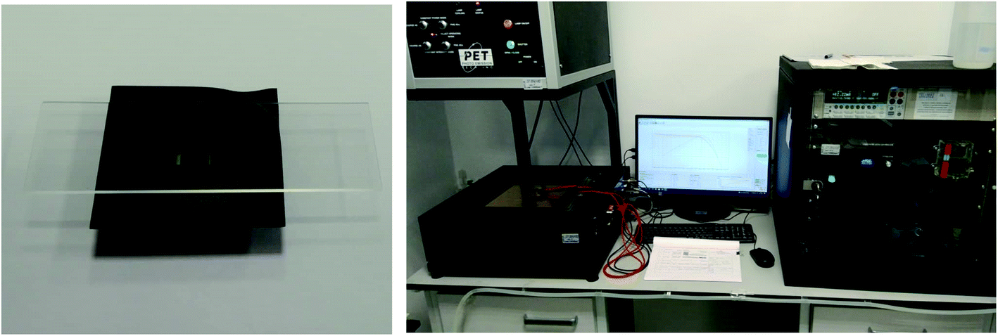 | ||
| Fig. 1 Images of dye-sensitized solar cells with a glass substrate coated by R3 together with the photovoltaic equipment used. | ||
To the best of our knowledge, this is the first paper investigating the influence of molecular weight of new siloxane resins on:
(i) The photovoltaic properties of both silicon and dye-sensitized solar cells and.
(ii) Thermal and electrical behaviour together with surface defects using a thermographic camera.
Experimental
Materials
All silanes and solvents were purchased from Sigma Aldrich Poland and used as received.A silicon solar cell with dimensions of 5 cm × 2 cm and parameters: VOC = 0.622 V; ISC = 328.4 mA; FF = 0.726; PCE = 14.8%, Rs = 204.45 mΩ and Rsh = 10.02 Ω, was obtained from Soltec (Warszawa, Poland).
A dye-sensitized solar cell (NR ref. 51201) with the active area of 0.36 cm2 and parameters of VOC = 0.669 V; ISC = 328.4 mA; FF = 0.726; PCE = 14.8%, Rs = 204.45 mΩ, and Rsh = 10.02 Ω, was provided by Solaronix (Aubonne, Switzerland).
Preparation of coating solutions
The resins were applied to the surface of the tested substrates from solutions of various concentrations in dibutyl ether or hexane using the spin-coating technique. The stock solutions of the resins were prepared by dissolving 6 g of each resin in 12 g of dibutyl ether or hexane, to which, after homogenization, 0.3 g of titanium tetrabutoxide as the condensation catalyst was added. Lower concentrations of the solutions were obtained by diluting the stock solutions with the appropriate solvent to the desired concentration. For comparison, the solutions of the silanes S1 and S2 used for the synthesis of the resins were prepared in the same manner.Methods
Infrared (FT-IR) spectra were recorded on a Bruker Tensor 27 Fourier transform spectrophotometer equipped with a diamond ATR unit. In all cases, 16 scans at a resolution of 2 cm−1 were collected to record the spectra in the range of 4000–500 cm−1.Gel permeation chromatography (GPC) analyses were performed using a Waters Alliance 2695 system equipped with a Waters 2414 RI detector and a set of three serially connected Waters HR columns (Waters Styragel HR1, HR2, and HR4). The measurements were carried out with THF as the mobile phase at a flow rate of 0.60 mL min−1; the column oven temperature was 35 °C and the detector temperature 40 °C. All molecular weight (Mn, Mw) and polydispersity index (PDI) values were calculated based on the calibration curve using polystyrene standards (Shodex) in the range of 1.31 × 10³ to 3.64 × 10⁶ Da.
Topography measurements were performed using a Nanosurf FlexAFM atomic force microscope (AFM) in intermittent contact mode. A PPP-NCLR cantilever with a resonance frequency of 190 kHz and stiffness of 48 N m−1 was used. Measurements were carried out in an air atmosphere.
Thermogravimetric analysis (TGA) was carried out using a TA Instruments TGA Q50 analyzer. The measurements were conducted in an air or N2 atmosphere at a flow rate of 60 mL min−1, in the temperature range of room temperature (RT) to 1000 °C at a heating rate of 10 K min−1.
Differential scattering calorimetry (DSC) measurements were carried out using a Mettler Toledo DSC-1 differential scanning calorimeter. Each sample was placed in 40 μL aluminum pans with a pierced lid and analyzed in an N2 atmosphere at a flow rate of 25 mL min−1 in the temperature range of −70 °C to 100 °C at a heating/cooling rate of 10 K min−1.
Transmission UV–Vis spectra in absorbance and transmittance mode in the range of 200–800 nm were acquired using an A360 UV–Vis spectrophotometer (AOR Instruments, Shanghai, China) with an interval of 0.2 nm and medium scan speed for thin layer samples. Samples were prepared via the spin coating technique (2000 rpm, 3000 rpm or 4000 rpm, 60 s) on sapphire glass, sodium lime glass or indium–tin oxide-coated glass as the support.
The reflectance was measured using a UV-visible-near infrared JascoV-770 spectrophotometer (Germany) equipped with an ILN-925 integrating sphere accessory for solid samples. The measured range was 190–800 nm at a scan rate of 100 nm min−1 with correction on the dark baseline.
Static contact angle measurements were carried out using an optical goniometer (Ossila Ltd, Sheffield, UK) supported by dedicated software. For the tests, a water drop (7 μL) was deposited on the sample surface. The contact angle was calculated using the tangent to the surface at the point of contact of three phases, i.e., solid, liquid and gas. The hydrophobic coating sample was cast on a surface of sapphire glass, sodium lime glass or indium–tin oxide-coated glass via spin coating (2000 rpm, 3000 rpm or 4000 rpm, 60 s).
Thermal behaviour was observed upon applying a potential using a thermographic camera (VIGOcam v50, VIGO System S.A, Ożarów Mazowiecki, Poland) and a multichannel potentiostat-galvanostat (PGStat Autolab M101, Metrohm, Barendrecht, Nederland), as described in detail elsewhere.35,36
The electrical parameters of the tested photovoltaic cells were determined using a measuring stand equipped with a solar radiation simulator of AAA class, model SS200AAA EM, manufactured by Photo Emission Tech., Inc. and an SS I–V CT-02 measurement system with software for determining the electrical parameters of the cells and the advanced analysis PV Test Solutions from Wrocław, Poland.37
The durability test was performed via the successive immersion of a glass substrate covered with a hydrophobic layer in a water bath for 5 min and swapping with cotton cloth. This procedure was repeated 5 times. After the experiment, contact angle measurements and photovoltaic tests were performed on a silicon cell placed on the top glass substrate covered with a hydrophobic layer.
Results and discussion
Synthesis of siloxane resins
The synthesis of siloxane resins was carried out based on the hydrolytic polycondensation of methyltrimethoxysilane (S1) in the case of the R1 resin or the hydrolytic co-polycondensation of methyltrimethoxysilane (S1), isobutyltrimethoxysilane (S2) and 3-methacroiloxypropyltrimethoxysilane or methyltrimethoxysilane (S1) and n-octyltriethoxysilane and 3-methacroiloxypropyltrimethoxysilane in the case of R2, and R3 resins, respectively, under alkaline conditions using tetrahydrofuran (THF) as the solvent according to the equations shown in Scheme 1.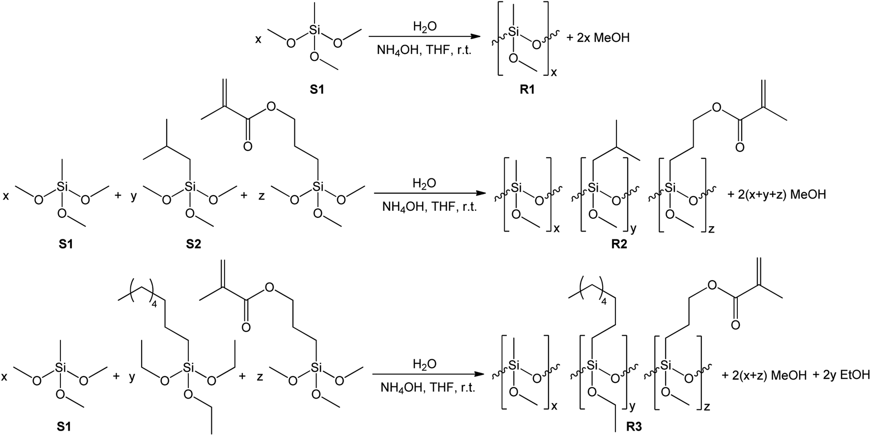 | ||
| Scheme 1 Synthesis of R1, R2, and R3 siloxane resins. | ||
The synthesis of the R1, R2, and R3 resins was carried out in a closed system under an air atmosphere at room temperature for 24 h with vigorous stirring. Methyltrimethoxysilane (in the case of R1) or a mixture of methyltrimethoxysilane, isobutyltrimethoxysilane, or n-octyltriethoxysilane and 3-methacroiloxypropyltrimethoxysilane (in case of R2 or R3 resins, respectively) were placed in the reactor together with THF as the solvent of volume equal to the mass of used organosilicon monomers. Next, ammonia-water solution was added dropwise to the obtained mixtures with vigorous stirring. The amount of water introduced in the reaction system was ca. 66% stoichiometric deficiency based on the number of alkoxy groups present in the organosilicon monomers. The exact amount of the reagents used for the synthesis of each of the resulting resins are shown in Table 1.
| Substrate | Resin | ||
|---|---|---|---|
| R1 | R2 | R3 | |
| Methyltrimethoxysilane (S1) [g] | 50 | 35 | 35 |
| Isobutyltrimethoxysilane (S2) [g] | — | 12.5 | — |
| n-Octyltriethoxysilane [g] | — | — | 12.5 |
| 3-Methacroiloxypropyltrimethoxysilane [g] | — | 2.5 | 2.5 |
| H2O [g] | 5.5 | 5 | 4.5 |
| NH4OHaq [g] | 1.5 | 1.5 | 1.5 |
| THF [mL] | 50 | 50 | 50 |
The R1, R2, and R3 resins were isolated from the reaction mixtures by evaporating the solvent and the alcohols formed during the hydrolytic condensation process under reduced pressure using a rotary evaporator. The obtained products in the form of viscous colorless liquid resins were subjected to spectroscopic (FT-IR) and chromatographic (GPC) analysis, and subsequently used for the preparation of the coating solutions.
FT-IR analysis
The obtained resins R1, R2, and R3 were subjected to FT-IR spectroscopic analysis to confirm their structure. The recorded FT-IR spectra of the prepared resins R1, R2, and R3 together with the spectra of the silanes used for their synthesis are presented in Fig. 2.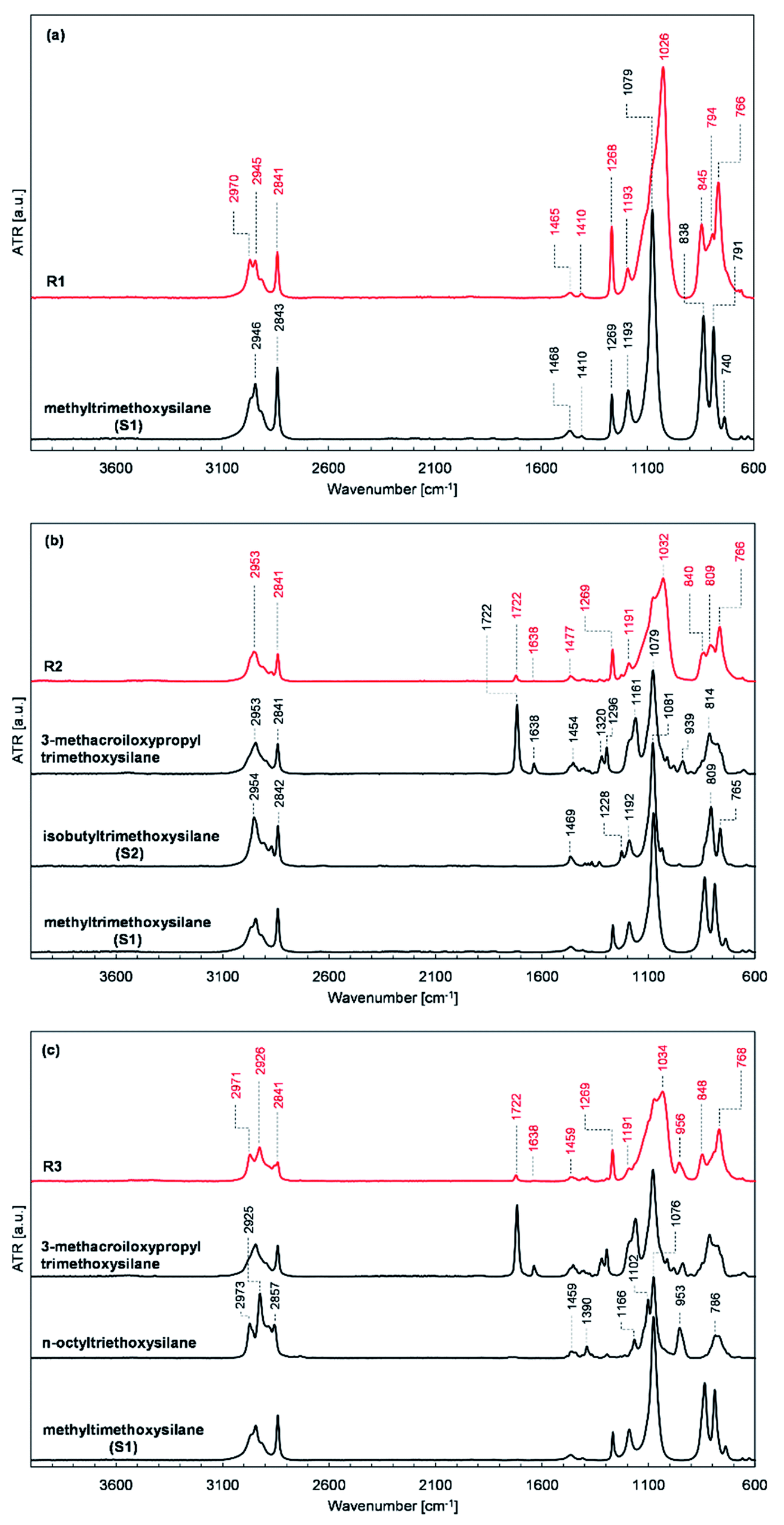 | ||
| Fig. 2 FT-IR spectra of (a) R1 resin and methyltrimethoxysilane, (b), R2 resin, 3-methacroiloxypropyltrimethoxysilane, isobutyltrimethoxysilane and, methyltrimethoxysilane, and (c) R3 resin, 3-methacroiloxypropyltrimethoxysilane, n-octyltriethoxysilane and methyltrimethoxysilane. | ||
The location and intensity of the absorption bands present in the FT-IR spectra of the prepared resins confirm their assumed structure and the expected course of the condensation process. The formation of siloxane bonds as a result of the condensation of the silanes used was evidenced by the appearance of high-intensity bands with maxima at about 1030 and 776 cm−1 in the spectra of resins R1, R2, and R3 (shown in Fig. 2a–c, respectively), which are characteristic of the stretching vibrations of the Si–O–Si bonds. Also, a reduction in the intensity of the characteristic band with a maximum at about 1090 cm−1 derived from Si–O–C bonds was present in the spectra of the silanes used compared to the characteristic band intensity with a maximum at 1270 cm−1 for Si–C bonds, which proves the assumed partial consumption of alkoxy groups in the starting monomers. The changes in the relative intensity and position of the bands present in the spectra of the tested resins in the range of 3000–2800 cm−1, which are characteristic for the stretching vibrations of the C–H bonds of the methyl and methylene groups and at 1722 and 1638 cm−1 present in the spectra of R2 and R3 resins (Fig. 2b and c, respectively), characteristic for the stretching vibrations of the C![[double bond, length as m-dash]](https://www.rsc.org/images/entities/char_e001.gif) O and CC bonds of the methacrylic group, compared to the relative intensity of bands present at the discussed wavenumbers in the spectra of the substrates used also prove the consumption of the OCH3 and OC2H5 groups.
O and CC bonds of the methacrylic group, compared to the relative intensity of bands present at the discussed wavenumbers in the spectra of the substrates used also prove the consumption of the OCH3 and OC2H5 groups.
GPC analysis
To determine the degree of polymerization and the molecular weight and molecular weight distribution of the obtained resins R1, R2 and, R3, their samples were subjected to GPC analysis. The molecular weight distribution plots and the measured molecular weights and their dispersity indices are presented in Fig. 3 and Table 2, respectively.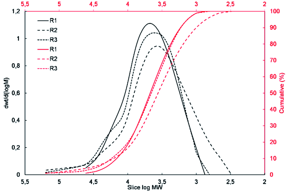 | ||
| Fig. 3 Molecular weight distribution plots for R1, R2, and R3 resins. | ||
| Resin | Mn [Da] | Mw [Da] | PDI | Resin composition |
|---|---|---|---|---|
| R1 | 3586 | 7084 | 1.975 | 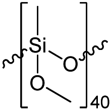 |
| R2 | 2325 | 10![[thin space (1/6-em)]](https://www.rsc.org/images/entities/char_2009.gif) 370 370 |
4.460 | 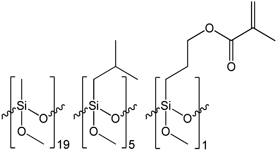 |
| R3 | 3528 | 10689 |
3.030 | 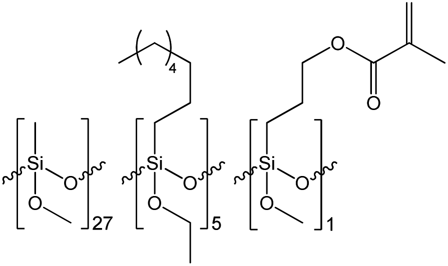 |
The results of the GPC analysis showed that the obtained resins were characterized by a rather low number average molecular weight (Mn) in the range of 2300 to 3600 Da and weight average molecular weight (Mw) in the range of 7100 to 10700 Da, which is characteristic for this type of materials.38,39 It can also be seen that the change in the type of reagents used and their molar ratio had an impact on the molecular weight and molecular weight distribution of the resulting resins. R1 resin obtained as a result of the polycondensation of only methyltrimethoxysilane (S1) was characterized by the lowest polydispersity index, which did not exceed 2. In the case of resins R2 and R3, which were obtained via the co-polycondensation of three different silanes, their polydispersity index increased to over 4 and 3, respectively. It can be observed that the increase in the molecular weight distribution is correlated with an increase in the molar fraction of the co-monomer used and affected by its different reactivity in the hydrolysis and condensation process.
Based on the results of the GPC analysis, the composition of the reaction mixtures, and the results of the FT-IR analysis, the probable compositions of the obtained resins were proposed and presented in Table 2.
TGA and DSC analysis
To assess the influence of the chemical composition of the resins on their thermal properties, the condensed resin samples were subjected to TGA and DSC analyses. The samples for analysis were prepared by pouring 2 g of each resin solution into a Petri dish and leaving them for 24 hours in the open air at room temperature to cross-link. The cross-link resins were peeled off the surface of the dishes and analyzed. The recorded TG and DTG curves in N2 and air atmosphere are shown in Fig. 4. | ||
| Fig. 4 TG and DTG curves for R1, R2 and, R3 resins in N2 atmosphere (a and b) and in air atmosphere (c and d), respectively. | ||
The results of the thermogravimetric analysis carried out in the N2 atmosphere (Fig. 4a and b) show that although the decomposition process of all the investigated resins proceeds similarly in four stages, their chemical structure (the amount of organic phase) has a key impact on their thermal stability. The maximum decomposition rate of the samples in their main decomposition stage taking place in the temperature range from about 375 °C to 600 °C increased from 0.05% °C−1 at 504 °C the R1 resin to 0.11% °C−1 at 519 °C for the R2 resin and 0.19% °C−1 at 484 °C for the R3 resin (Fig. 4b). The weight loss of the tested samples, observed in the discussed temperature range, also increased from 6.86% to 13.68% and 21.83% for the R1, R2 and, R3 resins, respectively (Fig. 4a). Simultaneously, the residue after analysis measured at 995 °C for the R1 resin sample was 81.7% of its initial weight, which decreased for the R2 and R3 resins to 75.1% and 67.4%, respectively (Fig. 4a).
An analogous dependence of the thermal stability of the tested samples on their chemical structure was observed for the analysis carried out in an air atmosphere (Fig. 4c and d). In this case, the difference observed was in the decomposition process, which proceeded in two stages in the temperature range of 200 °C to 450 °C and 450 °C to 650 °C. The maximum decomposition rate of the R1, R2, and R3 resin samples observed in the first stage increased from 0.08% °C−1 to 0.17% °C−1 and 0.22% °C−1, respectively (Fig. 4d). Simultaneously, the temperature of the maximum decomposition rate of the discussed samples decreased from 384 °C to 323 °C and 311 °C determined for the samples R1, R2, and R3, respectively. An inverse trend was observed in the second decomposition step in the range of 450 to 650 °C. The highest maximum decomposition rate of 0.14% °C−1 was observed in this case for the sample of resin R1 at 494 °C, which for the R2 and R3 resins samples dropped to 0.11% °C−1 at 510 °C and 0.08% °C−1 at 523 °C, respectively (Fig. 4d). The char yield after analysis measured at 995 °C for the R1, R2, and R3 resins was 79.4%, 68.9% and 64.4%, respectively (Fig. 4c).
The results of the thermogravimetric analysis showed that the R1 resin with the lowest organic fraction was characterized by the highest thermal resistance. The discussed values correlate well with the share of the organic fraction present in the tested resins, where a greater fraction affected the deterioration of the thermal properties of the investigated resins.
To further assess the influence of the chemical structure of the investigated resins on their thermal properties, their samples were also subjected to DSC analysis in the range of −70 °C to 100 °C (determined based on the TG analysis results). Unfortunately, the analysis of the obtained heat flow curves did not reveal any transitions in the discussed temperature range. The lack of a glass transition and melting and crystallization points can be explained by the high degree of cross-linking in the examined resins and their amorphous structure. Presumably, the glass transition point for the discussed systems occurs much higher than the initial temperature for their decomposition (100 °C), which is characteristic of many siloxane resins with a highly cross-linked structure.38
AFM analysis
To assess the influence of the structure of the active agent used for surface modification on the morphology of the modified substrates, they were analyzed using the AFM technique. Granular structures were observed on all analyzed samples, as shown in Fig. 5.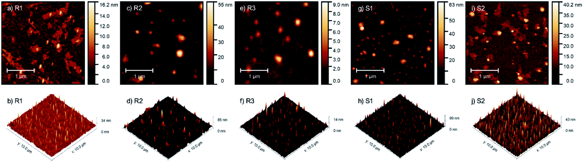 | ||
| Fig. 5 AFM micrographs and pseudo-3D images of glass substrates coated with R1 (a and b), R2 (c and d) and R3 (e and f) resins and S1 (g and h) and S2 (i and j) silanes. | ||
For sample S1, most of the structures had lateral dimensions of around 100 nm, whereas the single structures had dimensions of up to 400 nm in diameter. In sample S2, the observed structures also had two dimensions (about 70 and about 200 nm in diameter) but were additionally surrounded by non-regular islands, which were 3–4 nm high. These islands were in the form of a layer from which the granular structures grew. For sample R1, its morphology is similar to that of S2, where the only difference is the observation of only small granular objects with diameters of up to 100 nm. Sample R2 contained 100–200 nm grains, sometimes surrounded by a thin layer, but the area of the surrounding layer was much smaller than that on samples S2 and R1. The grains appearing on sample R3 were the most regular. Their diameter did not differ from that of the other samples, but their thickness was the smallest (not more than 10 nm). A roughness analysis of the characterized layers was also performed. The highest RMS roughness (Rq) value for the 3 × 3 micrometer area was observed for samples S1 (Rq = 5.25 nm) and R2 (Rq = 4.96 nm), and the lowest for R3 (Rq = 0.76 nm). The difference between them was more than six-fold. In contrast, S2 and R1 possessed Rq = 3.56 nm and 1.90 nm, respectively.
The issue of the influence of the chemical composition of the obtained resins on the surface morphology of the modified substrates is indeed interesting and requires in-depth research. Based on the comparison of the differences in the morphology of the samples modified with the use of silane S1 and resin R1 (with an analogous chemical composition), it can be concluded that the molecular structure (molecular or polymeric) determines the surface properties of the modified substrates. Alternatively, it is necessary to consider the different reactivities (susceptibility to hydrolysis and condensation) of the alkoxy groups present in silane S1 and resin R1, resulting from the different surroundings of the silicon atom to which these groups are attached, simultaneously bonding to the surface and to each other after deposition. Considering the partial similarity of the morphology of the substrates treated with silane S2 and resin R1, as well as the differences in the morphology of the samples treated with resins R2 and R3 with a different organic fraction, it should be considered that the type and number of organic groups also had a significant impact on the surface properties of the modified substrates, which is a known and widely used phenomenon, and on the above-mentioned reactivity of the alkoxy groups. The influence of the type of substrate was also significant, the change in which may also determine the other behaviors of the discussed modifiers. In conclusion, in our opinion, it is not only one factor, but the result of many variables (spatial structure, molecular weight, and functionality of modifier used and modified surface-starting properties). Considering this and to avoid drawing incorrect conclusions and generalizations based on insufficient data, the issue of the relationship between the morphology and chemical structure of the preparations used is not further discussed. We believe that planned, extended, and systematic research involving a greater number of silanes and resins will allow us to supplement the state of the art and answer emerging questions in the future.
UV-Vis study in absorbance, transmittance and reflectance mode
Firstly, the spectral study via UV-Vis spectroscopy was carried out for thin layers of R1, R2, R3, S1 and S2 on different glass substrates. The hydrophobic coating samples were cast on the surface of sapphire glass, sodium lime glass and indium-tin oxide-coated glass via spin coating (2000 rpm, 3000 rpm and 4000 rpm, 60 s). To register the signal coming from the used hydrophobic coatings, sapphire glass was used due to its very low absorption in the studied range. Fig. 6a presents a comparison of the spectral characteristics of all the samples. It was observed that in all the cases, the absorption in their UV-Vis spectrum is very flat with a signal below 300 nm. The R-family showed a broad single peak, with almost exponentially changing intensity, exhibited an increasing order of R1 < R2 < R3. The different intensities of the absorption maximum for the R-family are notable. M. Fujiki et al.40 reported that an increase in the length of the aliphatic substituents connected to silicon causes an increment in the intensity of the absorption maximum, which was also observed in our case. In the case of the S-family, the difference between both samples was not very significant and their intensity was comparable to that of the R1 sample.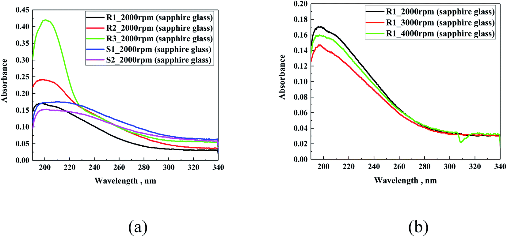 | ||
| Fig. 6 UV-Vis absorption spectra of all the investigated samples on sapphire glass at 2000 rpm (a) and sample R1 prepared at three different spreading velocities of 2000 rpm, 3000 rpm or 4000 rpm (b). | ||
In the second step, a comparison of the different layer thicknesses was performed. To ensure the difference in the thickness of the layer with the same coating, three different spin velocities were selected including 2000 rpm, 3000 rpm and 4000 rpm (Fig. 6b). For all the samples, the use of different velocities during the preparation process did not significantly influence the intensity of the signal, as can be observed for R1. These results raised a possible issue related to the uneven distribution of material during the solution spreading process, as confirmed in the AFM studies; however, it can be expected that with an increase in the spin velocity, the absorption spectra should show a decrease in the maximum signal intensity. Another possible explanation may be related to the formation of a porous structure after evaporation of the solvent.
In following step, the spectra of the samples prepared on different glass substrates were evaluated. For the study using sapphire glass with the lowest absorption in the tested range, and soda lime glass or indium–tin oxide-coated glass (ITO glass), as the most frequently used substrates for solar application, they were coated with a solution of different hydrophobic coatings. Fig. 7 presents the cumulative spectra of R1 on the three substrates, as an example. In the cases of soda lime glass and ITO glass, the characteristic absorbance of the studied materials was insignificantly low compared to the basic spectra of both supports, meaning that for future application the siloxane layer will not contribute to the overall absorption of glass-based substrates. In summary, the spectral characteristics of the five hydrophobic solutions clearly demonstrated that their use as an external coating as a protection should not limit the transparency of glass substrates.
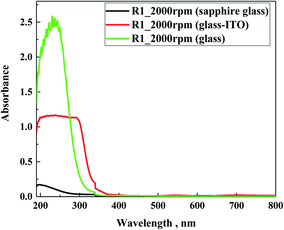 | ||
| Fig. 7 UV-Vis absorption spectra of R1 prepared on three different substrates. | ||
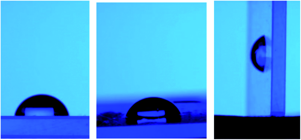
The transmittance spectra of the investigated samples (Fig. 8a) prepared on sapphire glass were very similar to that obtained in the absorption mode, as expected. All the samples showed a reduction in transmittance below 280 nm, which is in the same range as sodium lime glass. Moreover, Fig. 8b presents a photo of R3 prepared on soda lime glass at different dilutions.
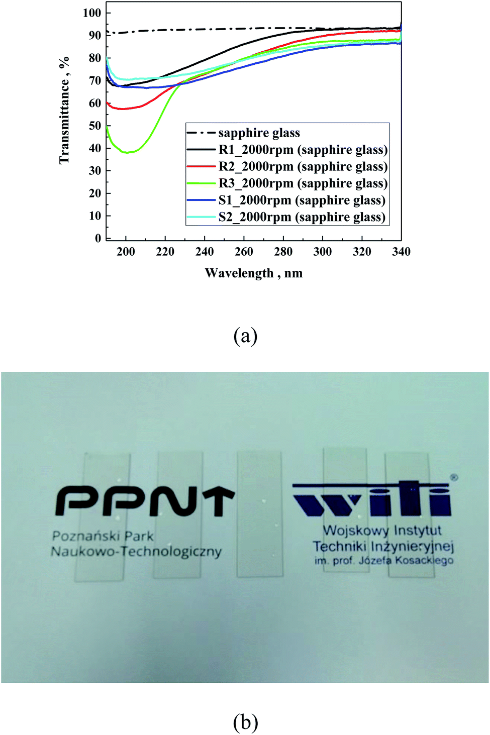 | ||
| Fig. 8 Transmittance spectra of samples prepared on sapphire glass (a) and photo of R3 (b), as an example prepared on sodium lime glass at different dilutions (from left to right): concentrated, 1:1, 1:2, 1:3 and 1:4. | ||
Also, the reflectance of the investigated samples on soda lime glass was tested (Fig. 9). As can be observed, the silane samples (S1 and S2) showed slightly higher refraction than the polysilane (R1–R3) of about 2.5%, which is lower than that on soda lime glass. In the case of the R-family samples, their refraction appeared below the glass substrate of about 1%. This suggests some antireflection properties, which follows the decreasing order of R1 < R3 < R2, particularly reflecting the average amount of methylmethoxysilane units in the polymeric chain of 40, 27 and 19 for R1, R3 and R2, respectively. Zha et al.41 observed that layers of mesoporous polysiloxane coatings can work as broadband antireflection coatings for samples containing methyltrimethoxy silane. In our case, it is evident that the higher the content of methylmethoxysilane units, the better the antireflecting properties.
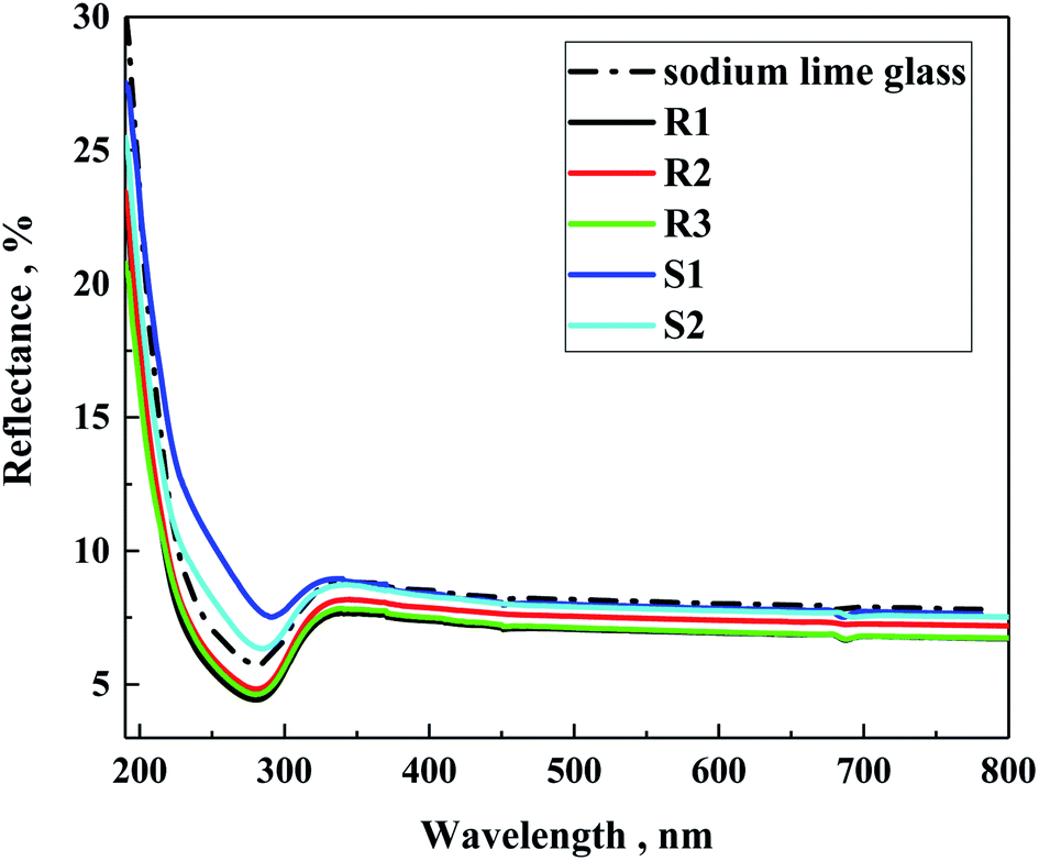 | ||
| Fig. 9 Reflectance spectra of the prepared samples on sodium lime glass. | ||
Static contact angle measurements
As their second feature, the hydrophobic nature of the formed layers was investigated using static contact angle measurements. The contact angle was calculated using the Ossila software and by measuring the angle between three phases including solid, liquid and gaseous. Table 3 contains the average contact measurement results. All the tested layers prepared with the R and S samples demonstrated a hydrophobic nature, as expected. The measured angles were above 100°. The highest angle value was observed for S2, which was 114.09°, whereas the lowest value was observed for S1. The shape of the drop did not change over a period of 5 h, evidencing that no moistening effect or penetration of the layer occurred.| Code | Contact angle, ° | Image |
|---|---|---|
| Glass | 45.30 | 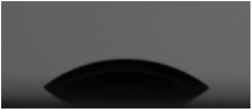 |
| R1 | 111.13 | 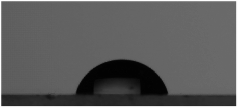 |
| R2 | 105.91 | 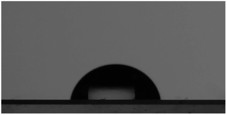 |
| R3 | 109.16 | 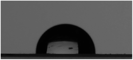 |
| S1 | 104.39 | 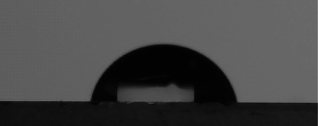 |
| S2 | 114.09 | 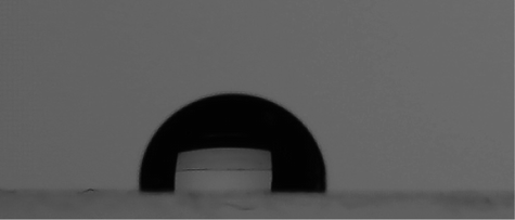 |
Table 4 presents the results of the water contact angle measurements for the R3 layers prepared from two different solvents used to prepare the developing solution (hexane or dibutyl ether) and in dilutions of 1:1, 1:2, 1:3, and 1:4. The dilutions were made by mixing the starting solution of silane in hexane or dibutyl ether with the same pure solvent. No mixed solutions were made to prepare the developing solutions. The results showed that the contact angle value did not change drastically with the dilution. The average value of the contact angle was found to be 108.30° ± 1.48°, which is consistent with the results presented in Table 3 for R3, confirming that regardless of the amount of solution used, the behaviour remained the same.
| Code | Contact angle, ° | Image |
|---|---|---|
| R3 (hexane) | 107.42 |  |
| R3 (1:1) |
110.45 | 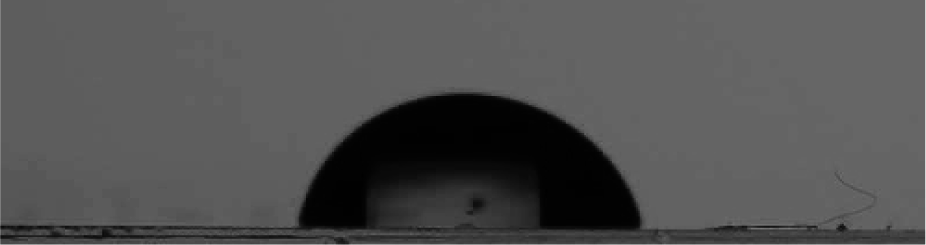 |
| R3 (1:2) |
106.64 |  |
| R3 (1:3) |
106.42 | 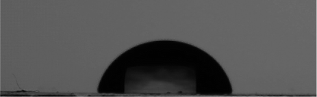 |
| R3 (1:4) |
107.2 | 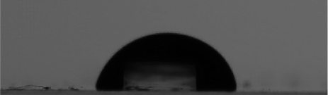 |
| R3 (dibutyl ether) | 108.61 | 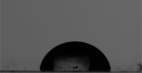 |
| R3 (1:1) |
110.08 | 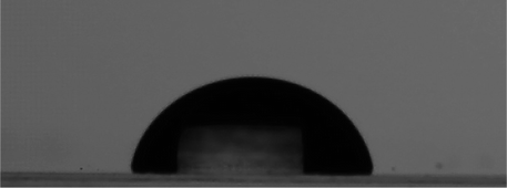 |
| R3 (1:2) |
110.00 | 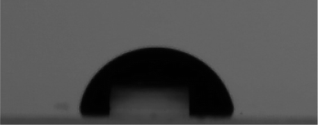 |
| R3 (1:3) |
107.59 |  |
| R3 (1:4) |
108.60 | 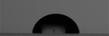 |
Additionally, after the water drop was deposited on the tested surface, the glass slide was inclined to initially reach 45°, and then 90° (see Fig. 10). It was observed that the adhesion forces between each coating and water drop were very strong. Additionally, the contact angle measurements for the R3 samples subjected to the durability test did not show any significant change in contact angle, which remained in the range observed for the other untreated samples, giving angles in the range of 106° to 110°.
 | ||
| Fig. 10 Water drop over the tested surface at an inclination angle (starting from the left): 0°, 45° and 90°. | ||
Thermal imaging study
To detect the possible formation of imperfections on the coatings based on the R- or S- component, the thermal images were recorded, while applying an external potential for devices with different architectures of glass/ITO/hydrophobic coating (see Fig. 11). In principle, all the hydrophobic coatings presented insulator-like behaviour, and therefore the measurement setup was prepared as follows: a single ITO-coated glass was coated completely with the hydrophobic coating via the spin coating method (2000 rpm, 60 s). Next, at both shorter sides of the glass, metal electrodes were pressed on the surface. To obtain the conductivity through the hydrophobic coating, silver conductive paste was used. When interpreting the results, it should be considered that the registered electric behaviour does not come only from studied layer but is a sum of factors such as porosity of the hydrophobic layer, mixing the properties of the layer with silver paste. In the case of thermal imaging, the heating effect is a secondary heating transferred from the conductive ITO layer to the hydrophobic coating. | ||
| Fig. 11 Current–voltage plot for all the samples performed in forward (a) and reverse (b) direction. | ||
Fig. 11 presents the recorded current–voltage curves for the different hydrophobic coatings. The fact that conductive behaviour was observed demonstrates that the principally non-conductive coatings mixed with silver conductive paste showed a certain level of conductivity. This finding suggests that the hydrophobic coating resembles a porous structure, enabling the formation of electrically conductive pathways. Moreover, a difference in conductive behaviour was observed. In the R-family, the conductivity followed the increasing order of R1 < R2 < R3, whereas that for the S-family was S1 < S2. It was observed that the conductivity of S2–R3 and S1–R2 was very similar (Fig. 11). The conductivity experiment was conducted in both directions, which means that after the first experiment, the polarization of the electrode switched, and thus the experiment was conducted in the opposite direction. It was found that the general tendency remained almost unchanged regardless the direction of the current flow.
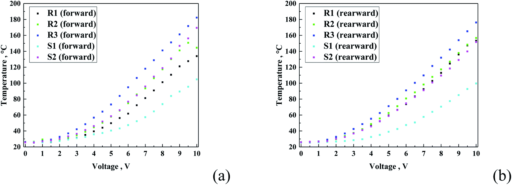
Fig. 12 presents the temperature vs. voltage graph. As expected, all the curves show a logarithmic-like shape, characteristic for heating transferred to the top layer. Also, in this case, the R-family exhibited the same increasing order, starting from the lowest observed temperature with R1 < R2 < R3, and for the S-family S1 < S2. In can be expected that the current values exhibited a proportional heating effect for all the samples. The results confirm this tendency only partially, namely, only in each family. It can be observed that the S-family coatings showed a lower temperature, as anticipated from the current–voltage curves. This can be related either to the specific composition of each sample or difference in porosity of the coating.
 | ||
| Fig. 12 Temperature vs. voltage graphs for all the samples for both forward (a) and reverse (b) directions. | ||
The analysis of the thermal images allowed the detection of different anomalies in the prepared coatings. As can be observed for the R-family coatings (Fig. 13a–c), small dotted imperfections were detected mainly close to the glass edges. These images suggest the formation of a continuous layer of the protective coating especially close to the surface borders. The analysis of the S-family show the absence of imperfections. Only an unusual overheating zone was observed at the centre of the sample. This may be partially related to the reflective nature of the used coatings. Also, the R3 samples prepared with different concentrations and two solvents were investigated. The results did not display a difference among the obtained results, within a measuring error of approx. 5%. These findings demonstrate that the formed thinner layers did not affect the total recorded images, which suggests that all the layers were formed in uniform fashion.
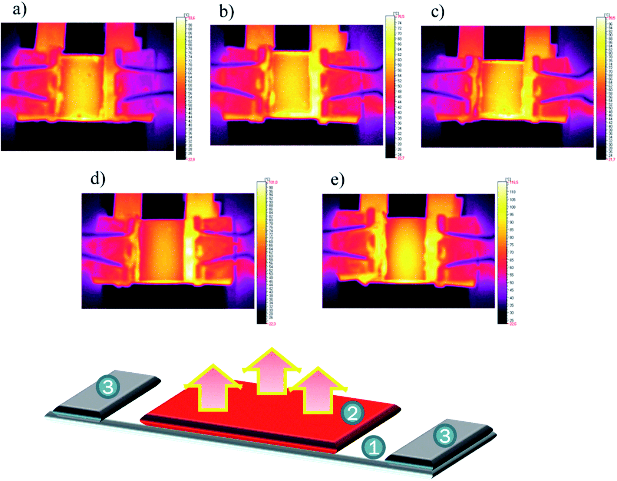 | ||
| Fig. 13 Thermal images of samples at 8 V: R1 (a), R2 (b), R3 (c), S1 (d) and S2 (e) together with a scheme of the experiment, where 1: glass/ITO, 2: investigated layer, and 3: electrodes. | ||
Photovoltaic study
Finally, the influence of the presence of a coating layer on two types of commercially available photovoltaic (PV) cells, i.e., silicon solar cells and dye-sensitized solar cells (DSSC), which are inorganic and organic solar cells, respectively, was studied. To reduce the influence of the organic components of the hydrophobic solution on the PV cell, the coatings were prepared on a glass slide and used to cover the device. The I–V parameters of the silicon solar cells covered with a pristine glass slide was open circuit voltage (Voc) of 603.88 mV, short circuit current (Isc) of 300.12 mA, fill factor (FF) of 0.69 and power conversion efficiency (PCE) of 12.25% (see Table 5). When the cover glass was replaced for the glass coated with a hydrophobic layer, the photovoltaic did not differ significantly from the original values, on the range of Voc 598.71–606.79 mV, Isc 300.09–319.67 mA and PCE 12.12–12.26%.| Code | ISC, mA | VOC, mV | Imax, mA | Vmax, mV | Pmax, mW | FF | PCE, % |
|---|---|---|---|---|---|---|---|
| Silicon solar cells | |||||||
| Glass cover | 300.12 | 603.88 | 272.23 | 460.61 | 125.39 | 0.69 | 12.25 |
| Glass/R1 | 301.30 | 600.95 | 274.45 | 457.26 | 125.50 | 0.69 | 12.26 |
| Glass/R2 | 300.09 | 600.88 | 273.33 | 457.98 | 125.18 | 0.69 | 12.25 |
| Glass/R3 | 300.47 | 598.71 | 273.15 | 455.75 | 124.49 | 0.69 | 12.18 |
| Glass/S1 | 323.40 | 606.59 | 294.29 | 459.77 | 135.31 | 0.69 | 12.25 |
| Glass/S2 | 319.67 | 600.79 | 289.70 | 456.47 | 132.24 | 0.69 | 12.12 |
Similar PV experiments were performed for the DSSC solar cells, as presented in Table 6. Deep analysis of the obtained results suggests that the type of used compounds did not influence the photovoltaic parameters of the investigated DSSCs. In this case, almost identical PV parameters were found for the DSSC without and with coating layers. As it can be seen in Fig. 14 and the data in Table 6, only a negligible fluctuation of approx. 1% was observed, which is consistent with the experimental error.
| Sample name | ISC, mA | VOC, mV | Imax, mA | Vmax, mV | Pmax, mW | FF | PCE, % |
|---|---|---|---|---|---|---|---|
| DSSC | |||||||
| Glass cover | 4.42 | 650.3 | 3.938 | 464.59 | 1.83 | 0.64 | 2.78 |
| Glass/R1 | 4.54 | 652.4 | 4.059 | 457.40 | 1.86 | 0.63 | 2.78 |
| Glass/R2 | 4.56 | 652.8 | 4.103 | 456.21 | 1.87 | 0.63 | 2.80 |
| Glass/R3 | 4.56 | 653.6 | 4.039 | 458.49 | 1.85 | 0.62 | 2.78 |
| Glass/S1 | 4.52 | 653.6 | 4.047 | 458.00 | 1.85 | 0.63 | 2.78 |
| Glass/S2 | 4.52 | 652.6 | 4.049 | 459.86 | 1.86 | 0.63 | 2.78 |
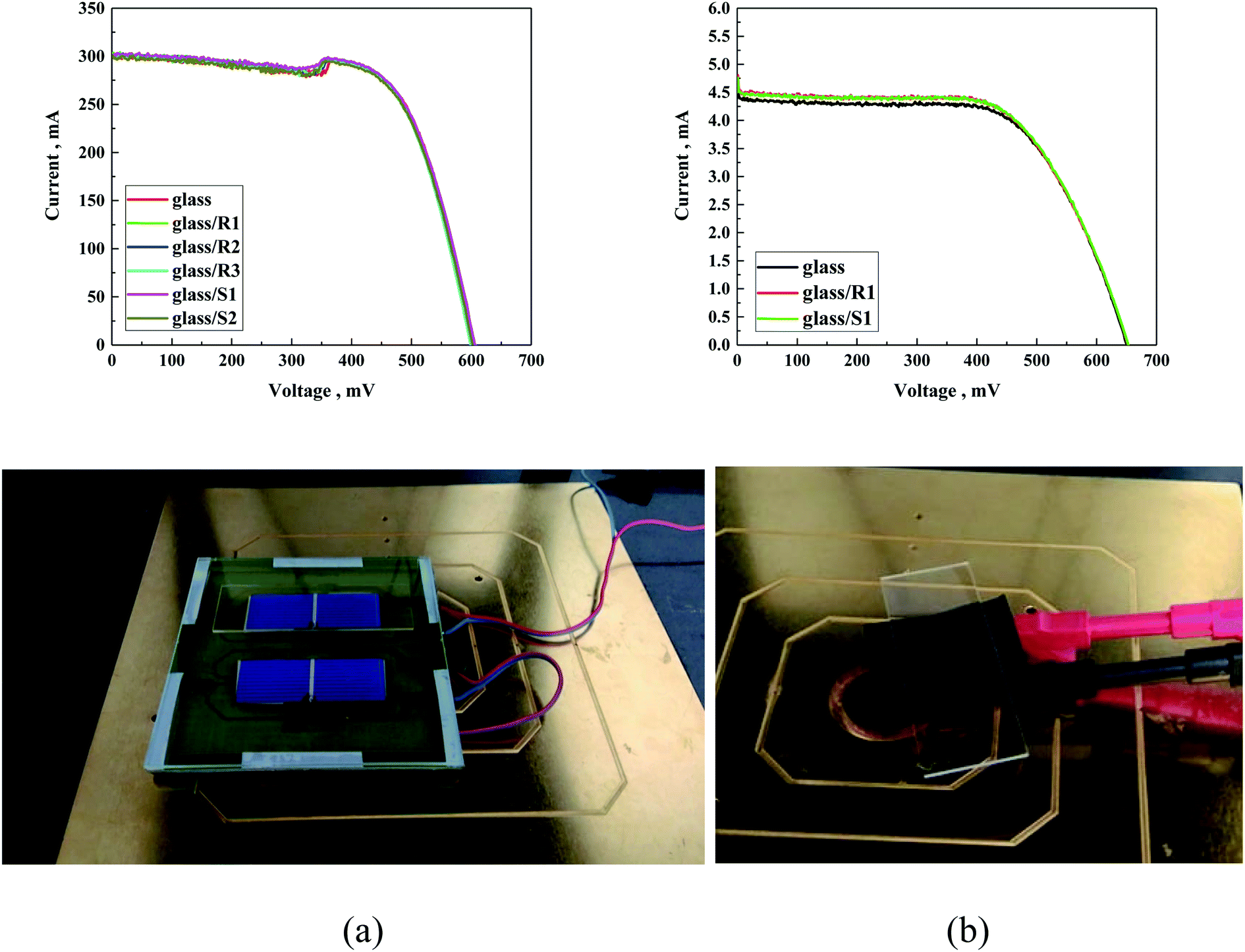 | ||
| Fig. 14 I–V curve of (a) silicon solar cells and (b) DSSC solar cells covered with differently modified glass and with photo of investigated solar cells. | ||
The small deviation in the values of some of the parameters can be ascribed to the slight temperature fluctuation in the solar cell. The approach of coating a protective layer on glass instead of directly covering the PV did not change the I–V characteristics of the used solar cell (Fig. 14).
Moreover, the experiment performed using samples that underwent durability tests did not present any deviation from the standard sample related to experimental error, both for the silicon and DSSC cells (Fig. 15).
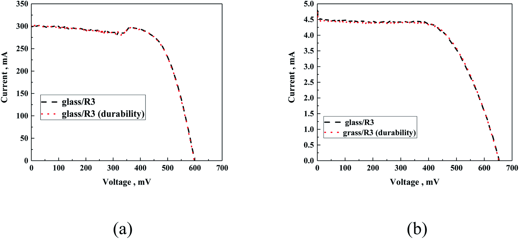 | ||
| Fig. 15 Exemplary I–V curves of silicon cell (a) and DSSC (b) covered with glass/R3 before and after the durability test. | ||
The obtained results are very significant compared to that with the use of TiO2 and TiO2–Ag by us previously as self-cleaning coatings for PV panels.37
Before presenting the conclusions, organosilicon derivatives of molecular or macromolecular structures (silanes, siloxanes, polysiloxanes, silsesquioxanes and silicone resins) are a group of compounds commonly applied as additives or precursors of formulations for the surface modification of various substrates. In this case, the choice of silicone resins as precursors of coating materials for the modification of the surface of photovoltaic panels and their chemical composition was dictated by both economic and technical considerations (the properties of the resins themselves). The materials for this type of application, due to their large-area use and the growing interest in the use of photovoltaic panels, should be characterized by a relatively low price, ease of application (not only in the laboratory but also in relevant/operational environment) and long application shelf life, while meeting key technical requirements (i.e., transparency, thermal, UV and oxidative stability and water repellency). Methyltrimethoxysilane (S1), which was used as the main component of the obtained resins, is the cheapest and most easily available trialkoxysilyl derivative on the market, which significantly reduces the cost of the materials obtained. Also, the method used for the synthesis of the resins does not require the use of complicated technological operations, equipment, and maintenance of specific process conditions, simultaneously enabling them to be obtained in high yield, which makes the whole process easily scalable. Silicone resin after drying and crosslinking enables the formation of durable films, which confer remarkable properties to the treated surfaces. They offer effective protection at constant temperatures of up to 250 °C and can withstand exposure to peak temperatures of up to 500 °C for short periods. They resist oxidation to and have good dielectric properties, even at temperatures of up to 250 °C, making them suitable for use in high-performance electrical insulation products. They also have excellent water-repellent characteristics and release properties, which prompted us to choose them as precursors of protective coatings for photovoltaic panels.
The advantage of using polymers (silicone resins) instead of silanes to modify the surface of photovoltaic cells is also based on the available knowledge and experience gathered during previous research, where it has been observed that low-molecular compounds (silanes) are much better for impregnating porous substrates, where by penetrating the pores of the material, they protect it from weather conditions, while maintaining the “breathability” of the material, which is not required in the case of photovoltaic panels. Alternatively, compounds with a macromolecular structure are much better at creating continuous and tight protective coatings on the surface of modified substrates without penetrating their pores. Therefore, in our opinion, the low porosity of the substrates used in the discussed research predetermined the use of resins in this case.
The ability of resins to create uniform coatings was also confirmed by the results of the AFM microscopic measurements presented herein. The surface of the sample treated with the S1-based formulation was much rougher than that of the sample covered with the R1 resin with an analogous chemical composition. The roughness of the samples treated with silane S2 and resin R2 was relatively high and close, which may be the result of the steric hindrance caused by the presence of isobutyl groups. The sample covered with R3 resin was characterized by the most homogeneous and smoothest surface. Overall, this seems to confirm the theory that the use of resins instead of silanes to modify low porosity substrates enables the formation of more homogeneous coatings.
Conclusions
In summary, three new siloxane resins were synthesized and verified in depth by experimental studies. Selected properties of the siloxane resins were compared with silanes as comonomers. As mentioned, the different reactivities of the alkoxy groups present in the used comonomers influenced the molecular weight and molecular weight distribution of the obtained polymers. This was also the result of the different mass fraction of organic functional groups present in the tested resins compared to the mass fraction of the inorganic phase (siloxane chains). This was reflected in the measured thermal, optical, and electrical parameters, the changes of which always followed the same trend (R1 < R2 < R3) with an increase in the amount of organic phase. A similar dependency was also observed for the tested silanes (S1 and S2), which also differed in the mass fraction of the organic part.The main conclusions are as follows:
• The layers prepared with different dilutions showed the same behaviour regardless of their thickness, suggesting that the external layer has the same hydrophobic character.
• The transmittance and reflectance of the organic layers showed that they did not affect the properties of the glass support, and in the case of the studied polymers, antireflective behaviour was observed.
• The use of concentrated solutions to prepare the samples was beneficial for the mechanical resistance of the protective layer, where even thinner layers (obtained using diluted samples) possessed the same properties in terms of hydrophobicity and thermoelectrical properties.
• Proposed siloxane resins can be used as self-cleaning coatings for inorganic and organic solar cells as simple to prepare compounds, which did not influence the photovoltaic parameters of the solar cells.
Our study showed that the proposed siloxane resins can be used as self-cleaning layers prepared via single-step coating and are attractive compared with commercial hydrophobic surfaces based on the Lotus effect considering environmental and cost aspects. The estimated cost of obtaining the resin based on the current unit cost of individual materials is around 10–30 Euro kg−1 (depending on the resin type), which would be reduced with global production. The proposed process of protecting solar cells with glass covered with a self-cleaning layer has both protective and utility functions given that the proposed solutions can be used many times for various generations of solar cells, which should reduce the amount of waste generated, in accordance with the principles of green chemistry and recycling.
Author contributions
Krzysztof Artur Bogdanowicz: investigation, analyses, writing – oOriginal draft preparation, Michał Dutkiewicz: investigation, analyses, writing – original draft preparation, Hieronim Maciejewski: writing – reviewing and editing, Marek Nowicki: investigation, Wojciech Przybył: investigation, Ireneusz Plebankiewicz: investigation, Agnieszka Iwan: writing – original draft preparation, writing – reviewing and editing, conceptualization, analyses. All authors have read and agreed to the published version of the manuscript.Conflicts of interest
There are no conflicts to declare.Acknowledgements
Authors (AI and KAB) are grateful for financial support from Polish National Centre of Research and Development (TECHMATSTRATEG1/347431/14/NCBR/2018).References
- N. F. Zainuddin, M. N. Mohammed, S. Al-Zubaidi and S. I. Khogali, Design and Development of Smart Self-Cleaning Solar Panel System, 2019 IEEE International Conference on Automatic Control and Intelligent Systems, 2019, pp. 40–43, 978-1-7281-0784-4/19/$31.00©2019 IEEE Search PubMed.
- C. S. Psomopoulos, K. D. Mardikis, N. G. Katsikas and G. C. Ioannidis, Harvesting the sun's energy in EU-27. A review, Proceedings of the 12th International Conference on Protection and Restoration of the Environment, ed. A. Liakopoulos, A. Kungolos, C. Christodoulatos and A. Koutsopsyros, 2014, pp. 999–1006, ISBN 978-960-88490-6-8 Search PubMed.
- Solar Energy in the United States, accessed online on February 21st 2022, webpage, https://www.energy.gov/eere/solar/solar-energy-united-states Search PubMed.
- H. Can Baş, Strong growth predicted for Middle Eastern solar PV, accessed online on February 21st 2022, https://www.pv-magazine.com/2021/06/25/strong-growth-predicted-for-middle-eastern-solar-pv/ Search PubMed.
- A. Blakers, J. Luther and A. Nadolny, Asia Pacific Super Grid – Solar electricity generation, storage and distribution, Green, 2012, 2(4), 189–202, DOI:10.1515/green-2012-00.
- G. He, C. Zhou and Z. Li, Review of Self-Cleaning Method for Solar Cell Array, Procedia Eng., 2011, 16, 640–645, DOI:10.1016/j.proeng.2011.08.1135.
- B. Kobin, Self-cleaning Technologies for Solar Panels, n-tech Research Publication, Glen Allen, Virginia, US, 2018 Search PubMed.
- K. Midtdal and B. P. Jelle, Self-cleaning glazing products: A state-of-the-art review and future research pathways, Sol. Energy Mater. Sol. Cells, 2013, 109, 126–141, DOI:10.1016/j.solmat.2012.09.034.
- P. Centeno, M. F. Alexandre, M. Chapa, J. V. Pinto, J. Deuermeier, T. Mateus, E. Fortunato, R. Martins, H. Águas and M. J. Mendes, Self-Cleaned Photonic-Enhanced Solar Cells with Nanostructured Parylene-C, Adv. Mater. Interfaces, 2020, 2000264, DOI:10.1002/admi.202000264.
- C. M. Gronet and J. K. Truman, Self-cleaning protective coatings for use with photovoltaic cells, US Pat., 8344238B2, 2013 Search PubMed.
- K. Abushgair and R. Al-Waked, Effects of Coating Materials as a Cleaning Agent on the Performance of Poly-Crystal PV Panels, Coatings, 2021, 11, 544, DOI:10.3390/coatings11050544.
- Z. Liang, Z. Zhou, L. Zhao, B. Donga and S. Wang, Fabrication of transparent, durable and self-cleaning superhydrophobic coatings for solar cells, New J. Chem., 2020, 44, 14481–14489, 10.1039/D0NJ01402H.
- P. Wang, H. Wang, J. Li, L. Ni, L. Wang and J. Xie, A superhydrophobic film of photovoltaic modules and self-cleaning performance, Sol. Energy, 2021, 226, 92–99, DOI:10.1016/j.solener.2021.08.018.
- S. Sutha, S. Suresh, B. Raj and K. R. Ravi, Transparent alumina based superhydrophobic self–cleaning coatings for solar cell cover glass applications, Sol. Energy Mater. Sol. Cells, 2017, 165, 128–137, DOI:10.1016/j.solmat.2017.02.027.
- A. Ayaz, H. Ahmad, F. Ahmad, A. Khan, S. M. Hasnain Tarmazi, R. M. Gul and S. Saher, Self-cleaning of glass surface to maximize the PV cell efficiency, IOP Conf. Ser.: Mater. Sci. Eng., 2020, 899, 012006 CrossRef CAS.
- S. Maharjan, K.-S. Liao, A. J. Wang, K. Barton, A. Haldar, N. J. Alley, H. J. Byrne and S. A. Curran, Self-cleaning hydrophobic nanocoating on glass: a scalable manufacturing process, Mater. Chem. Phys., 2019, 239, 122000 CrossRef.
- C. Robeyns, L. Picard and F. Ganachaud, Synthesis, characterization and modification of silicone resins: An “Augmented Review”, Prog. Org. Coat., 2018, 125, 287–315, DOI:10.1016/j.porgcoat.2018.03.025.
- Silicon Containing Polymers: The Science and Technology of Their Synthesis and Applications, ed. R. G. Jones, W. Ando and J. Chojnowski, Springer, Dordrecht, 2000, DOI:10.1007/978-94-011-3939-7.
- M. Le Cramer, G. D. Correll and N. L. Osenbach, US2005/0065294 A1, 2005.
- R. Wen, J. Huo, J. Lv, Z. Liu and Y. Yu, Effect of silicone resin modification on the performance of epoxy materials for LED encapsulation, J. Mater. Sci.: Mater. Electron., 2017, 28, 14522–14535, DOI:10.1007/s10854-017-7316-5.
- M. Kujawa, WO2012/052439A1, 2012.
- H. Mayer, Masonry protection with silanes, siloxanes and silicone resins, Surf. Coat. Int., 1998, 81(2), 89–93, DOI:10.1007/BF02692337.
- A. J. Burzynski and R. E. Martin, FR1443437A, 1965.
- P. J. Varaprath and P. J. M. Vincent, US5152984A, 1992.
- I. MacKinnon, D. L. Ou and P. M. Chevalier, WO2002/081552A1, 2002.
- T. D. Bekemeier, US2013/0030115A1, 2013.
- S. Liu, Y. Fu, Z. Jiang, J. Zhao and C. Zhang, Synthesis and characterization of soluble and meltable poly(aminopropyl/phenylsilsesquioxane), J. Wuhan Univ. Technol., Mater. Sci. Ed., 2009, 24, 945–951, DOI:10.1007/s11595-009-6945-9.
- V. Rerat and D. Pierre, WO2013/072370A2, 2013.
- M. Kilinc, D. Pierre and V. Rerat, US2014/316045A1, 2014.
- M. Backer, P. Chevalier, Z. Liu, A. Marques, S. Onodera, V. Rerat and M. Sasaki, US2013/0066009A1, 2013.
- B. Q. H. Nguyen, A. Shanmugasundaram, T.-F. Hou, J. Park and D.-W. Lee, Realizing the flexible and transparent highly-hydrophobic film through siloxane functionalized polyurethane-acrylate micro-pattern, Chem. Eng. J., 2019, 373, 68–77, DOI:10.1016/j.cej.2019.04.197.
- H. Zhong, Y. Hu, Y. Wang and H. Yang, TiO2/silane coupling agent composed of two layers structure: A super-hydrophilic self-cleaning coating applied in PV panels, Appl. Energy, 2017, 204, 932–938, DOI:10.1016/j.apenergy.2017.04.057.
- T.-F. Hou, A. Shanmugasundaram, B. Q. H. Nguyen and D.-W. Lee, Fabrication of surface-functionalized PUA composites to achieve superhydrophobicity, Micro Nano Syst. Lett., 2019, 7, 12, DOI:10.1186/s40486-019-0090-9.
- S.-S. Yoon, G.-R. Lee and D.-Y. Khang, Contact-printed ultrathin siloxane passivation layer for high-performance Si-PEDOT:PSS hybrid solar cells, Microelectron. Eng., 2017, 170, 1–7, DOI:10.1016/j.mee.2016.12.006.
- A. Różycka, K. A. Bogdanowicz, N. Górska, J. Rysz, M. Marzec, A. Iwan, R. Pich and A. Januszko, Influence of TiO2 nanoparticles on liquid crystalline, structural and electrochemical properties of (8z)-n-(4-((z)-(4-pentylphenylimino)methyl)benzylidene)-4-pentylbenzenamine, Materials, 2019, 12, 1097, DOI:10.3390/ma12071097.
- K. A. Bogdanowicz and A. Iwan, Review on thermoelectrical properties of selected imines in neat and multicomponent layers towards organic opto-electronics and photovoltaics, Opto-Electron. Rev., 2021, 29, 201–212, DOI:10.24425/opelre.2021.139754.
- A. Gonciarz, R. Pich, K. A. Bogdanowicz, K. Drabczyk, A. Sypien, Ł. Major and A. Iwan, TiO2 and TiO2–Ag powders and thin layer toward self-cleaning coatings for PV panel integrated with sound-absorbing screens: Technical approaches, Journal of Power Sources Advances, 2021, 8, 100053, DOI:10.1016/j.powera.2021.100053.
- E. Tatarinova, N. Vasilenko and A. Muzafarov, Synthesis and Properties of MQ Copolymers: Current State of Knowledge, Molecules, 2017, 22, 1768, DOI:10.3390/molecules22101768.
- T. Takahashi, J. Kaschta and H. Munstedt, Melt rheology and structure of silicone resins, Rheol. Acta, 2001, 40, 490–498, DOI:10.1007/s003970100173.
- M. Fujiki, J. R. Koe, K. Terao, T. Sato, A. Teramoto and J. Watanabe, Optically Active Polysilanes. Ten Years of Progress and New Polymer Twist for Nanoscience and Nanotechnology, Polym. J., 2003, 35, 297–344, DOI:10.1295/polymj.35.297.
- J. Zha, X. Lu and Z. Xin, A rational design of double layer mesoporous polysiloxane coatings for broadband antireflection, J. Sol-Gel Sci. Technol., 2015, 74, 677–684, DOI:10.1007/s10971-015-3648-x.
| This journal is © The Royal Society of Chemistry 2022 |