 Open Access Article
Synergistic effect of reduced graphene oxide/carbon nanotube hybrid papers on cross-plane thermal and mechanical properties
Yan Yang ,
Honglie Shen*,
Jiale Yang,
Kai Gao
 ,
Zehui Wang and
Luanhong Sun
College of Materials Science and Technology, Jiangsu Key Laboratory of Materials and Technology for Energy Conversion, Nanjing University of Aeronautics and Astronautics, Nanjing, 210016, PR China. E-mail: hlshen@nuaa.edu.cn
First published on 30th June 2022
Abstract
Graphene paper has attracted great attention as a heat dissipation material due to its excellent thermal conductivity and mechanical properties. However, the thermal conductivity of graphene paper in the normal direction is relatively poor. In this work, the cross-plane thermal conductivities (K⊥) and mechanical properties of the reduced graphene oxide/carbon nanotube papers with different CNT loadings were studied systematically. It was found that the K⊥ decreased from 0.0393 W m−1 K−1 for 0 wt% paper to 0.0250 W m−1 K−1 for 3 wt% paper, and then increased to 0.1199 W m−1 K−1 for 20 wt% paper. The papers demonstrated a maximum elastic modulus of 6.1 GPa with 10 wt% CNT loading. The CNTs acted as scaffolds to restrain the graphene sheets from corrugating and to reinforce the mechanical properties of the hybrid papers. The more CNTs that filled the gaps between graphene sheets, the greater the number of channels of the transmission of phonons and the looser the structure in the cross-plane direction. Further mechanism analysis revealed the synergistic effects of CNT loadings and graphene sheets on enhancing the thermal and mechanical performance of the papers.
1. Introduction
Modern electronic devices with increasing power densities require ultrahigh heat dissipation materials to dissipate the temperature of thermosensitive components. Advanced heat dissipation materials, including carbon allotropes and their derivatives,1,2 have become essential for the reliability and long service life of these electronic devices due to their unique ability of high thermal conductivity, flexibility, lightweight and excellent corrosion resistance.In recent years, paper-like graphene films as lateral heat spreaders have attracted extensive attention for their ultrahigh in-plane thermal conductivity and flexibility.3,4 Gao et al.5 reported that the free-standing graphene papers with in-plane thermal conductivity of 1940 W m−1 K−1 and high fracture elongation of 16% were successfully fabricated by thermal annealing up to 3000 °C. The outstanding performances of thermal conductivity for the free-standing graphene paper were mainly attributed to the restoration of the sp2 structure in the 3000 °C graphitization process. However, when it comes to thermal management systems,6,7 such as the gaskets of aircrafts in aerospace industries, the heat can be transmitted in the normal direction. Thus, the thermal and mechanical performances of graphene paper in the cross-plane are very critical, which gives graphene paper wider application, such as in electronic sensors8 and pressure sensors.9
Carbon nanotubes (CNTs) are generally used as nano-fillers to enhance the thermal conductivity of polymeric composites10–12 and the theoretical thermal conductivity of CNTs in the axial direction is ∼3000–3500 W m−1 k−1.13 With the high axial conductivity of CNTs, it is reasonable to build graphene/CNTs (G/CNTs) hybrids structure aiming at improving the cross-plane thermal conductivity of rGO papers. Varshney et al.14 investigated thermal transportation in a novel 3-D pillared-graphene architecture, and the nonequilibrium molecular dynamics simulations suggested that the introduction of carbon nanoring (CNR) significantly enhanced the thermal conductivity in an axial direction. Jiang et al.15 fabricated a 3D bridged CNR/graphene hybrid paper by in situ growth of CNR, in which the CNRs were covalently bonded to the graphene sheets and a favorable thermal conductivity of 5.81 W m−1 K−1 was obtained. Feng et al.16 prepared CNTs/exfoliated graphite block (EGB) by growing CNTs at the surface of SiO2-coated exfoliated graphite plate (EGP), and the results showed a maximum K⊥ of 38 W m−1 K−1 and an increased bending strength (76 MPa), which could be attributed to the bridge of CNTs and EGPs in the cross-plane direction. Tai et al.17 found that the cross-plane thermal conductivity of the rGO/CNTs hybrid films increased with the increase of CNTs loadings. A considerable improvement of K⊥ (0.091 W m−1 K−1) was obtained, mainly because the CNTs provide more heat transfer pathways in the cross-plane direction than in the in-plane direction.
However, the aforementioned methods for growing CNTs in graphene intercalation to improve the cross-plane thermal conductivities and mechanical properties are not suitable for industrial production due to low outputs. The feasible way to produce graphene materials for industry-scale applications in thermal management is to first prepare GO by the Hummers' method,18 and then reduce GO by thermal reduction,19 chemical reduction20 or laser reduction methods.21 Moreover, the mechanical mold sacrifices the flexibility of the graphene films. Therefore, despite the high heat transfer performance and excellent flexibility of individual graphene sheets, it is still a great challenge for macroscopically assembled materials to have great mechanical properties and high thermal conductivity at the same time. The cross-plane properties of the hierarchies rGO/CNTs papers and the synergistic effects between CNTs and rGO sheets are seldom reported. The cross-plane thermal and mechanical properties of the rGO/CNTs hybrid papers should be further investigated for future various applications, such as thermal management15,16 and strain sensor.22
In this paper, the rGO/CNTs hybrid papers with different CNTs loadings were prepared by vacuum filtration followed by thermal reduction. The cross-plane thermal conductivities were evaluated by the laser flash method. The nanoindentation was employed to study the elastic modulus and hardness of the rGO/CNTs papers. To reveal the synergistic effects between CNTs and rGO sheets in the hierarchical rGO/CNTs hybrid paper, the effects of different CNTs loadings on the cross-plane thermal conductivities and mechanical properties of the hybrid papers were systematically studied. As a result, a favorable cross-plane thermal conductivity and elastic modulus for rGO/CNTs hybrid paper were obtained. It is suggested by a synergistic effect that CNTs intercalated in rGO sheets reinforced the paper structure and played a positive role in providing more paths for phonon transmission, therefore improving thermal conductivity.
2. Experimental section
2.1 Materials
Graphene oxide powder was prepared by a modified Hummers' method by natural graphite (325 mesh, Shanghai Macklin Biochemical Co., Ltd, China). Details of the method were reported everywhere.18,23 CNTs powder (TNM3, outer diameter between 10–20 nm, length between 10–20 μm) was purchased from Chengdu Organic Chemicals Co., Ltd, China. The as-received CNTs were purified by thermal treatment in argon at 450 °C for 60 min to remove amorphous carbon.2.2 Preparation of rGO/CNTs papers
The preparation process of rGO/CNTs paper mainly consists of two steps. In the first step, the hybrid GO/CNTs papers with different amounts of CNTs doping were successfully fabricated by vacuum filtration. The mixture of the as-papered GO powder (20 mg) and different amounts of CNTs (0 wt%, 1 wt%, 3 wt%, 5 wt%, 10 wt%, 15 wt%, 20 wt%) was added into deionized water by probe ultrasonication for 15 min at the power of 350 W. The GO/CNTs papers were prepared by vacuum filtration of the pre-mixture by using nylon-66 membranes filters (50 mm in diameter, 0.45 μm in pore size). The as-prepared papers were dried at 45 °C followed by peeling off from the membranes.In the second step, The GO/CNTs papers were annealed at 1000 °C for the deoxidation process. The thermal treatment process is as follows: first, the GO/CNTs papers were heated from room temperature to 300 °C at a rate of 1 °C min−1, and kept at 300 °C for 60 min under an argon flow of 300 sccm; then the temperature was increased from 300 °C to 1000 °C at a rate of 2 °C min−1, and kept at 1000 °C for 60 min under an argon flow of 300 sccm. Afterward, the samples were naturally cooled to room temperature with argon protection at a flow of 300 sccm. The as-prepared samples were described as rGO, rGO/CNTs-1%, rGO/CNTs-3%, rGO/CNTs-5%, rGO/CNTs-10%, rGO/CNTs-15%, rGO/CNTs-20%, respectively.
2.3 Characterization
The morphologies of as-prepared samples were characterized by scanning electron micrometer (SEM, TESCAN, LYRA3) and transmission electron microscopy (TEM, JEOL 2100F). The diffraction behavior was characterized by X-ray diffraction (XRD, an X'Pert PRO MPD). Raman spectroscopy was performed using a Renishaw inVia apparatus (excitation laser k = 532 nm) on the prepared papers. X-ray photoelectron spectroscopy (XPS) was carried out on an ESCALAB250Xi spectrometer. The mechanical properties of the prepared papers were characterized by the nanoindentation device (CSM Nano Indenter, NHT2+MST) equipped with a Berkovich diamond probe with a radius of approximately 100 nm.The thermal conductivity (k) of all samples was calculated using eqn (1):
| k = ρ·Cp·α | (1) |
| ρ = m·V−1 | (2) |
| V = πr2d | (3) |
3. Results and discussion
3.1 Samples preparation and structure characterizations
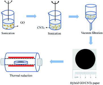
The hydrophilic groups such as hydroxyl, epoxy, and carboxyl groups on the basal plane and edges of the GO sheets allow it to form a stable aqueous solution.24 However, the hydrophobicity of CNTs makes them difficult to disperse in water. When GO powder and CNTs were mixed to prepare an aqueous solution, the sidewalls of CNTs adhered to the GO basal plane through π–π supramolecular interaction and the hydrophilic groups of GO sheets maintain the water dispersibility of GO/CNTs.24,25 Fig. 1 presents the schematic diagram of the preparation of rGO/CNTs papers. CNTs were mixed with GO solution followed by probe ultrasonication. A stable dispersion was formed and then the hybrid GO/CNTs papers were prepared by vacuum filtration method. The thermal reduction at 1000 °C was employed to obtain the hybrid rGO/CNTs papers. The optical photograph of the hybrid rGO/CNTs papers with different CNTs loadings is displayed in Fig. 2(a). The color of the hybrid rGO/CNTs papers changes from gray to black with the increasing CNTs loadings. The rGO paper without CNTs shows a rough surface and contains many bubbles and wrinkles. The amounts of wrinkles and bubbles show a decreasing trend with the increasing CNTs loadings, which is attributed to the prevention of graphene sheet corrugation by CNTs.26 The addition of CNTs macroscopically improves the smoothness of the hybrid rGO/CNTs papers and reinforces the hybrid papers. The obtained rGO/CNTs-10% paper shown in Fig. 2(b) exhibited flexibility and metallic luster and the corresponding cross-plane SEM image in Fig. 2(c) shows uniform dispersion of CNTs across the rGO layers. The macroscopic smooth surface can reduce the phono scattering and the seamless structure lessen the modulus mismatch of phonons transmission in the cross-plane,17 which increases the cross-plane thermal and mechanical properties of the hybrid papers.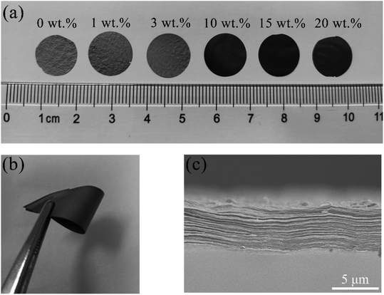 | ||
| Fig. 2 (a) Photograph of rGO/CNTs papers of different CNTs loadings. (b) Photograph of the rGO/CNTs-10% paper. (c) The corresponding cross-plane SEM image of the RGO/CNTs-10% paper. | ||
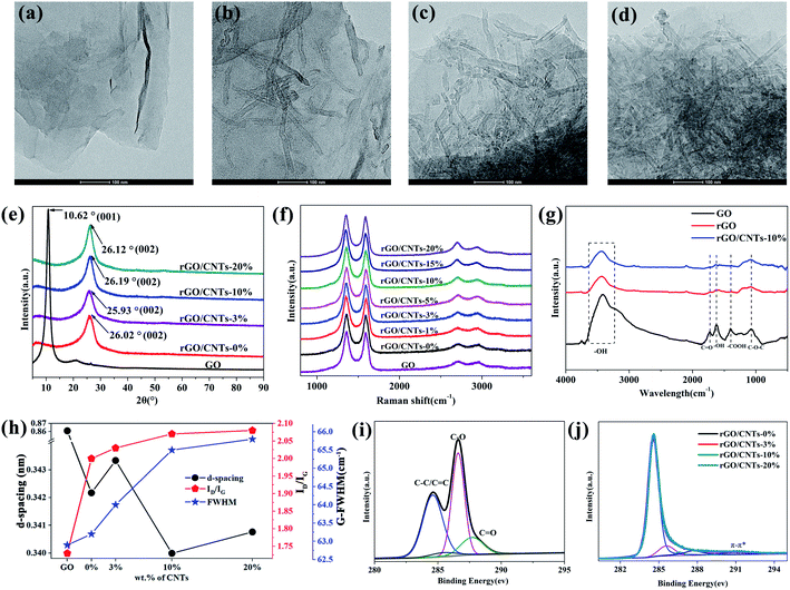
As for the rGO/CNTs hybrid papers, CNTs are intercalated into the graphene sheets. TEM was adopted to inspect the microstructural observation of rGO/CNTs hybrid papers, as depicted in Fig. 3(a)–(d). The micrographs shown in Fig. 3(a) clearly illustrated that the CNTs rGO/CNTs-0% possess a layered structure. Fig. 3(b)–(d) exhibit that the graphene sheets are homogeneously co-dispersed with CNTs. When the loadings of CNTs are as high as 20 wt%, there is slight agglomeration.
XRD was employed to investigate the structure evolution from GO to rGO/CNTs. As shown in Fig. 3(e), GO shows a peak at 10.62° corresponding to the (001) plane.17,27 According to the Bragg equation, the d-spacing of the GO paper is 8.61 Å, which is larger than that of natural graphite (26.5°, d-spacing ∼ 3.35 Å),15 owing to oxygen-containing functional groups introduced by intercalation reaction in the oxidation process. After thermal reduction, the XRD pattern of rGO shows that the peak becomes the border and the position shifts to around 26°. Moreover, the characteristic diffraction peaks of rGO/CNTs-0%, rGO/CNTs-3%, rGO/CNTs-10%, rGO/CNTs-20% are at 26.02°, 25.93°, 26.19° and 26.12°, respectively. The corresponding d-spacing of these samples are 3.42 Å, 3.43 Å, 3.40 Å and 3.41 Å, respectively. The d-spacing variation as a function of different CNTs loadings is presented in Fig. 3(h). The d-spacing increased from 3.42 Å for rGO/CNTs-0% to 3.43 Å for rGO/CNTs-3%, which may be due to the loading of carbon nanotubes limiting the ripple during the deoxidation of rGO plates at 1000 °C,26 the slightly straightened graphene sheets will make the graphene layers looser. The macroscopic corrugations of rGO/CNTs-3% in the photograph illustrated in Fig. 2(a) also prove that the graphene sheets are not fully straightened. After continuing to increase the loading of carbon nanotubes, the d-spacing decreases to 3.40 Å for rGO/CNTs-10%, which is due to the fact that the graphene sheets are continuously straightened by the more carbon nanotubes, and the straightened graphene sheets without corrugations are easier to align stacked together. The macroscopically smooth surface of rGO/CNTs-10% in the photograph illustrated in Fig. 2(a) proves that the graphene sheets are further straightened. The increased d-spacing of rGO/CNTs-20% should be due to the fact that excess disordered carbon nanotubes would mess up the aligned graphene sheets, leading to the loose stacking of graphene sheets.
Fig. 3(f) shows the Raman spectra of GO and rGO/CNTs hybrid papers. The peak at around 1360 cm−1 (D peak) is assigned to defects (non-carbon atoms, vacancies, disordered structure and so on) in graphitic structure.28 The D peak is interpreted as disorder-induced Raman modes, which is caused by the double resonant Raman scattering process involving κ-point phonons.29 It is worth noting that there is no D peak in the single-crystal graphite. The peak at about 1590 cm−1 (G peak) corresponds to the first-order Raman scattering of an E2g optical mode, representing a highly ordered structure in graphite.30 The relative intensity ratio of ID/IG and the full width at half maximum (FWHM) of the G peak are used to characterize the degree of structure disorder.30 Fig. 3(h) shows that the ID/IG ratio is 1.73 for GO, 2.00 for rGO/CNTs-0%, 2.03 for rGO/CNTs-3%, 2.07 for rGO/CNTs-10% and 2.08 for rGO/CNTs-20%, respectively. Besides, a similar trend shown in Fig. 3(f) is observed for the FWHM of the G peak. The FWHM of the G peak increase with the increasing CNTs loadings. The increases in ratios of ID/IG from 1.73 for GO to 2.00 for rGO/CNTs-0% are owing to the desorption of oxygen bonded saturated sp3 carbons as CO2 and CO. Various topological defects and vacancies are generated in the graphene lattice.27 The ratio ID/IG and the FWHM of the G peak increase slightly with the increasing CNTs loadings, which may be due to the fact that the straightened graphene sheets generated more defects. More recovery of the sp2 region in graphitic lattice requires further graphitization at above 2000 °C, which is uneconomic in industry and unavailable for our experimental conditions.26
The functional groups of the rGO/CNTs hybrid papers were investigated by FTIR, as shown in Fig. 3(g). All the samples show a wide peak at approximately 3400 cm−1, which is attributed to the –OH stretching vibration mode in intercalated H2O and/or carboxyl.31 The peaks at 1730 cm−1 for C![[double bond, length as m-dash]](https://www.rsc.org/images/entities/char_e001.gif) O stretching vibration, 1389 cm−1 for –OH bending vibration, and 1062 cm−1 for C–OH stretching vibration in the spectra of GO/CNTs-0% and GO/CNTs-10% become almost invisible compared with those of GO, indicating that the functional groups have been mostly removed after thermal reduction. The remaining strong peak at approximately 1630 cm−1 is attributed to C
O stretching vibration, 1389 cm−1 for –OH bending vibration, and 1062 cm−1 for C–OH stretching vibration in the spectra of GO/CNTs-0% and GO/CNTs-10% become almost invisible compared with those of GO, indicating that the functional groups have been mostly removed after thermal reduction. The remaining strong peak at approximately 1630 cm−1 is attributed to C![[double bond, length as m-dash]](https://www.rsc.org/images/entities/char_e001.gif) C stretching vibration from the effective sp2 hybrid region repairing during thermal reduction. Therefore, it is confirmed that the thermal reduction used in this study can effectively remove most of the oxygen-containing functional groups, as a result, enhancing the mechanical and electrical properties of rGO and rGO/CNTs papers.
C stretching vibration from the effective sp2 hybrid region repairing during thermal reduction. Therefore, it is confirmed that the thermal reduction used in this study can effectively remove most of the oxygen-containing functional groups, as a result, enhancing the mechanical and electrical properties of rGO and rGO/CNTs papers.
XPS was used to further characterize the chemical bonding and the valance states of the samples. C 1s XPS spectra for the original GO paper and the rGO/CNTs hybrid papers are shown in Fig. 3(i) and (j). The C 1s spectrum can be deconvoluted into four Gaussian peaks arising from sp2 C (∼284.6 eV), sp3 C (∼285.5 eV), C–O (∼286.5), C![[double bond, length as m-dash]](https://www.rsc.org/images/entities/char_e001.gif) O (∼287.9).19 The C 1s spectrum shown in Fig. 3(j) for the rGO/CNTs-0%, rGO/CNTs-3%, rGO/CNTs-10%, rGO/CNTs-20% almost completely overlapped. For the rGO/CNTs hybrid papers, the low-intensity broad peaks observed at binding energies of ∼291.1 eV can be assigned to a (π–π*) shakeup satellite peak.
O (∼287.9).19 The C 1s spectrum shown in Fig. 3(j) for the rGO/CNTs-0%, rGO/CNTs-3%, rGO/CNTs-10%, rGO/CNTs-20% almost completely overlapped. For the rGO/CNTs hybrid papers, the low-intensity broad peaks observed at binding energies of ∼291.1 eV can be assigned to a (π–π*) shakeup satellite peak.
3.2 Morphology of the rGO/CNTs hybrid papers
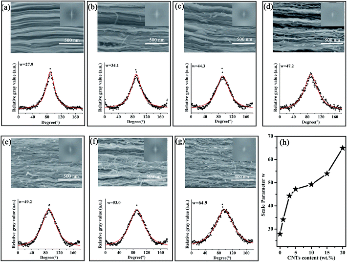
Fig. 4 shows the cross-sectional SEM images of rGO/CNTs hybrid papers (left). The cross-sectional observation of rGO in Fig. 4(a) shows nearly perfectly aligned rGO sheets. As shown in Fig. 4(b–g), the rGO/CNTs hybrid papers with different CNTs loading shows a sandwich structure with CNTs embedded into the interlayer of reduced graphene oxide layers. As the loading of CNTs increases, the thickness of the rGO/CNTs hybrid papers increases from 2.9 μm for rGO paper to 6.8 μm for rGO/CNTs-20%. The thicknesses of the hybrid papers are presented in Table 1.| Sample | rGO | rGO/CNTs-1% | rGO/CNTs-3% | rGO/CNTs-5% | rGO/CNTs-10% | rGO/CNTs-15% | rGO/CNTs-20% |
|---|---|---|---|---|---|---|---|
| Thickness (μm) | 2.9 | 3.3 | 3.5 | 3.9 | 4.3 | 5.2 | 6.8 |
In this paper, the fast Fourier transform (FFT) method was used to quantitatively characterize the degree of alignment of rGO/CNTs hybrid papers.32–34 In SEM images, each pixel possesses its gray value. The fast Fourier transform (FFT) is to convert the gray distribution spectrum f(x, y) of the image into the frequency distribution spectrum F(u, v) of the image. Using the software ImageJ, FFT is implemented on each 1.1 μm × 1.5 μm SEM image in Fig. 4(a–g) (up), the frequency spectrums can be easily obtained by the following formula:
 | (4) |
The as-obtained FFT frequency curves are shown in Fig. 4(a–g) (inset). Furthermore, the frequency distribution spectrum characterizes the amplitude variation of the gray value, which is the gradient of grayscale on the two-dimensional plane. Consequently, the frequency spectrum obtained by the FFT method can be processed for analyzing the spatial alignment properties of carbon fiber and collagen bundles.35 The following Cauchy-Lorentz distribution is used to fit the angle distribution of the intensity in the frequency spectrum:
 | (5) |
3.3 Cross-plane thermal conductive performance of the rGO/CNTs hybrid papers
The cross-plane thermal conductivity (K⊥) and cross-plane thermal diffusivity (α⊥) of the rGO/CNTs hybrid papers are summarized in Fig. 5(a) and (b), respectively. When the CNTs loadings increase from 0 wt% to 3 wt%, both the K⊥ and α⊥ are reduced; K⊥ decreases from 0.0393 to 0.0250 W m−1 K−1 and α⊥ descends from 0.0256 to 0.0167 mm2 s−1. In contrast, when the CNTs loading keeps increasing, the K⊥and α⊥ are significantly increased to 0.1199 W m−1 K−1 and 0.0983 mm2 s−1 for rGO/CNTs-20%, respectively.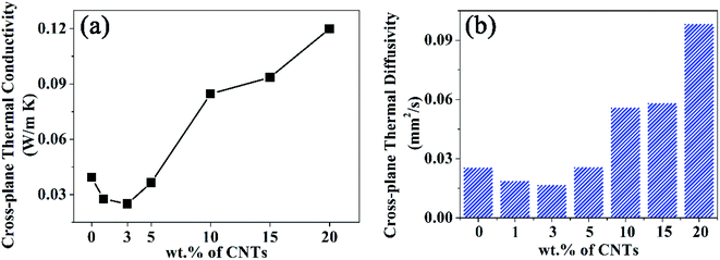 | ||
| Fig. 5 (a) Cross-plane thermal conductivities and (b) cross-plane thermal diffusivities for hybrid rGO/CNTs papers as a function of CNTs loadings. | ||
As can be seen from the macro photo shown in Fig. 2(a), the surfaces of the rGO/CNTs hybrid papers become smoother with the increasing loading CNTs, which is also confirmed by the top-view SEM images in Fig. 6(a,c and e). The top-view of SEM images of the hybrid papers and the corresponding schematic diagram of rGO/CNTs hybrid structure with different spacer CNTs loadings are shown in Fig. 6. The rGO paper exhibits a corrugated surface (Fig. 6(a)), as commonly found in pure rGO paper.36 The corrugated rGO sheets provide paths for heat conduction in the cross-plane direction. As shown in Fig. 6(c), the 3 wt% CNTs are sparsely and uniformly dispersed on the graphene layer. The smoother surfaces obtained by the introduction of CNTs are owning to the CNTs restraining the corrugation of graphene sheets during the deoxygenation process. When the rGO/CNTs hybrid papers contain high loadings of CNTs (Fig. 6(e)), the CNTs will be stacked to form a layered network dispersed on the graphene layer. The CNTs layered stacked network forms a loose structure in the vertical direction of rGO/CNTs hybrid papers.
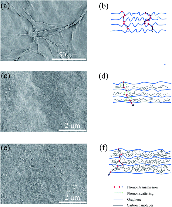 | ||
| Fig. 6 The top-view SEM images for rGO, rGO/CNT-3%, rGO/CNTs-20% (a, c and e). The corresponding schematic diagram of rGO/CNTs hybrid structure with different spacer CNTs loadings (b, d and f). | ||
It is considered that the cross-plane thermal conductivity performance of rGO/CNTs hybrid papers comes from the 3D bridged CNTs/graphene sheets via the synergistic effect. On one hand, the introduction of sparse CNTs restrains the corrugation of graphene sheets and straightens the graphene sheets during deoxygenation at 1000 °C. The corrugated graphene sheets observed in Fig. 6(b) are not completely aligned perpendicularly to the cross-plane direction and then a significant contribution to the K⊥ is made by the in-plane thermal conductivity of the graphene sheets with a theoretical K∥ up to 5300 W m−1 K−1. However, the graphene sheets straightened by sparse CNTs disappear the contribution of in-plane graphene sheets' heat conduction to the cross-plane direction, and this makes the interlayer of films filled with air, which is not conducive to the transfer of heat. Therefore, when the amount of CNTs is less than 3 wt%, the K⊥ exhibits a decreasing trend with the increasing CNTs loading. On the other hand, the induction of CNTs fills the interspace of graphene sheets and bridges the graphene sheets. The CNTs network provides channels for phonons transmission in a cross-plane direction. Therefore, when the introduction of CNTs is more than 3 wt%, the K⊥ exhibits an increasing trend with the increasing CNTs loading. The K⊥ of 0.1199 W m−1 K−1 for rGO/CNTs-20% is about three times as much as that of rGO (0.0393 W m−1 K−1). It is suggested that CNTs play an important role in improving the cross-plane thermal conductivity of the hybrid rGO/CNTs papers.
3.4 Cross-plane mechanical performance of the rGO/CNTs hybrid papers
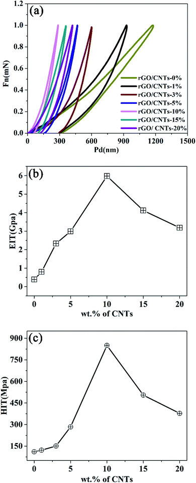
To evaluate the potential application for the rGO/CNTs hybrid papers, the mechanical properties of the rGO/CNTs hybrid papers were investigated by typical nanoindentation. Atomic force microscopy (AFM) is unstable due to the discontinuous movement of the microcantilever.37 However, the nanoindentation system has good stability. Fig. 7(a) shows the load–displacement curves of the rGO/CNTs hybrid papers with maximum constant loads of 1 mN. The elastic modulus and hardness of the rGO/CNTs hybrid papers are calculated by the load–displacement curves using the Oliver–Pharr method.38The elastic modulus (EIT) and hardness (HIT) of the rGO/CNTs papers are examined as a function of the loading of CNTs. As shown in Fig. 7(b), the rGO paper has an elastic modulus of 0.39 GPa; and the value increases to 6.1 GPa with the CNTs loading increasing to 10%. However, the elastic modulus rapidly drops to 3.19 GPa in terms of 20% CNTs. The hardness illustrated in Fig. 7(c) shows similar patterns compared with the elastic modulus curves. As the introduction of CNTs increases from 0 wt% to 10 wt%, the hardness of the rGO/CNTs paper increases from 110.80 MPa to 850.24 MPa, and then decreases to 377.79 MPa when it comes to 20%. As shown in Fig. 7(b and c), the 10 wt% appears to be a critical percentage of CNTs in the rGO/CNTs hybrid papers. This is because when the loading of CNTs is 10 wt%, the stack of rGO/CNTs-10% hybrid paper is the most aligned, and the distance between the graphene sheets (d-spacing) is the smallest, which is supported by the XRD pattern (Fig. 3(e)). The dense structure makes EIT and HIT the largest when the CNTs loading is 10%.
Fig. 6(c) shows that the CNTs are encapsulated by graphene sheets as uniform paper. Meanwhile, the SEM cross-plane images indicate that CNTs are sandwiched in the interspace of the graphene sheets with almost every CNT fully covered. In this full-carbon architecture, the CNTs and graphene sheets are stacked layer by layer to form a 3D hierarchical structure. Herein, the CNTs are selected as the scaffolds to reinforce the mechanical properties of the rGO/CNTs hybrid papers.
As shown in Fig. 6(e), when the CNTs loading is more than 20 wt%, the CNTs network is formed due to the restricted space for encapsulated CNTs. Therefore, some of the CNTs are bent or overlapped at the interspace of graphene sheets, where alignments of the rGO/CNTs hybrid papers decrease (as shown in Fig. 4(h)). The overlapped CNTs network leads to a relatively loose structure of the rGO/CNTs papers, which causes declines in the elastic modulus and hardness of the rGO/CNTs papers. The loose structure caused by CNTs can be applied to pressure sensors.39
4. Conclusion
The rGO/CNTs hybrid papers were prepared by utilizing CNTs intercalation in graphene layers. The results showed that rGO/CNTs hybrid paper with the 20 wt% CNTs loadings showed an optimal cross-plane thermal conductivity of 0.1199 W m−1 K−1, which was about three times to that of rGO papers (0.0393 W m−1 K−1). Moreover, the rGO/CNTs hybrid paper with the 3 wt% CNTs loadings possesses a minimum cross-plane thermal conductivity of 0.0250 W m−1 K−1, which is 64 percent of that of rGO papers (0.0393 W m−1 K−1). However, the hybrid paper with 10 wt% CNTs loadings showed the maximum elastic modulus of 6.1 GPa, which is 15 times greater than that of rGO papers (0.39 GPa). These were ascribed to the hierarchical architecture, in which CNTs were employed to restrain the graphene sheets corrugated during high temperatures and filled the interspace in the graphene layers. When the loading of CNTs is 10 wt%, the stack of rGO/CNTs-10% hybrid paper is the most aligned and the dense structure makes EIT and HIT the largest when the CNTs loading is 10%. Besides, the CNTs network formed at higher CNTs loading (such as 20 wt%) provided efficient transmission channels for phonons. The combined improved cross-plane thermal conductivity and mechanical properties render the rGO/CNTs hybrid paper advanced materials in thermal management.Conflicts of interest
There are no conflicts to declare.Acknowledgements
This work has been financially supported by the National Natural Science Foundation of China (61774084), the Priority Academic Program Development of Jiangsu Higher Education Institutions, the special fund of Jiangsu Province for the transformation of scientific and technological achievements (BA2019047), the open project of Key Laboratory of Materials Preparation and Protection for Harsh Environment, Ministry of Industry and Information Technology (XCA20013-3) and by funding of Jiangsu Innovation Program for Graduate Education (KYCX19_0175).References
- Y. Zhu, Q. Y. Peng, Y. Y. Qin, X. Zhao, L. L. Xu, Q. Chen, Y. Li, Z. H. Xu and X. D. He, Graphene-Carbon Composite Films as Thermal Management Materials, ACS Appl. Nano Mater., 2020, 3, 9076–9087, DOI:10.1021/acsanm.0c01754.
- G. Q. Xin, H. T. Sun, T. Hu, H. Rasisi Fard, X. Sun, N. Koratkar, T. Borca-Tasciuc and J. Lian, Large-Area Freestanding Graphene Paper for Superior Thermal Management, Adv. Mater., 2014, 26, 4521–4526, DOI:10.1002/adma.201400951.
- P. Li, M. Yang, Y. Liu, H. Qin and C. Gao, Continuous crystalline graphene papers with gigapascal strength by intercalation modulated plasticization, Nat. Commun., 2020, 11, 2645, DOI:10.1038/s41467-020-16494-0.
- H. L. Li, S. C. Dai, J. Miao, X. Wu, N. Chandrasekharan, H. X. Qiu and J. H. Yang, Enhanced thermal conductivity of graphene/polyimide hybrid film via a novel “molecular welding” strategy, Carbon, 2017, 126, 319–327, DOI:10.1016/j.carbon.2017.10.044.
- L. Peng, Z. Xu, Z. Liu, Y. Guo, P. Li and C. Gao, Ultrahigh Thermal Conductive yet Superflexible Graphene Films, Adv. Mater., 2017, 29, 1700589, DOI:10.1002/adma.201700589.
- S. Sihn, S. Ganguli, A. K. Roy, L. T. Qu and L. M. Dai, Enhancement of through-thickness thermal conductivity in adhesively bonded joints using aligned carbon nanotubes, Compos. Sci. Technol., 2008, 68, 658–665, DOI:10.1016/j.compscitech.2007.09.016.
- H. Jung, S. Yu, N. S. Bae, S. M. Cho, R. H. Kim, S. H. Cho, I. Hwang, B. Jeong, J. S. Ryu, J. Hwang, S. M. Hong, C. M. Koo and C. Park, High through-plane thermal conduction of graphene nanoflake filled polymer composites melt-processed in an L-shape kinked tube, ACS Appl. Mater. Interfaces, 2015, 7, 15256–15262, DOI:10.1021/acsami.5b02681.
- S. Zhang, S. Li, Z. Xia and K. Y. Cai, A review of electronic skin: soft electronics and sensors for human health, J. Mater. Chem. B, 2020, 8, 852–862, 10.1039/C9TB02531F.
- D. Y. Wang, L. Q. Tao, Y. Liu, T. Y. Zhang, Y. Pang, Q. Wang, S. Jiang, Y. Yang and T. L. Ren, High performance flexible strain sensor based on self-locked overlapping graphene sheets, Nanoscale, 2016, 8, 20090–20095, 10.1039/c6nr07620c.
- A. J. Wang, K. S. Liao, S. Maharjan, Z. Zhu, B. McElhenny, J. M. Bao and S. A. Curran, Percolating conductive networks in multiwall carbon nanotube-filled polymeric nanocomposites: towards scalable high-conductivity applications of disordered systems, Nanoscale, 2019, 11, 8565–8578, 10.1039/C9NR00216B.
- S. X. Nie, J. L. Mo, Y. H. Zhang, C. Y. Xiong and S. F. Wang, Ultra-high thermal-conductive, reduced graphene oxide welded cellulose nanofibrils network for efficient thermal management, Carbohydr. Polym., 2020, 250, 116971, DOI:10.1016/j.carbpol.2020.116971.
- S. Sathyanarayana, C. Hüebner, J. Diemert, P. Pötschke and F. Henning, Influence of peroxide addition on the morphology and properties of polypropylene-multiwalled carbon nanotube nanocomposites, Compos. Sci. Technol., 2013, 84, 78–85, DOI:10.1016/j.compscitech.2013.05.008.
- M. Fujii, X. Zhang, H. Q. Xie, H. Ago, K. Takahashi, T. Ikuta, H. Abe and T. Shimizu, Measuring the Thermal Conductivity of a Single Carbon Nanotube, Phys. Rev. Lett., 2005, 95, 065502, DOI:10.1103/PhysRevLett.95.065502.
- V. Varshney, S. S. Patnaik, A. K. Roy, G. Froudakis and B. L. Farmer, Modeling of thermal transport in pillared-graphene architectures, ACS Nano, 2010, 4, 1153–1161, DOI:10.1021/nn901341r.
- J. W. Zhang, G. Shi, C. Jiang, S. Ju and D. Z. Jiang, 3D Bridged Carbon Nanoring/Graphene Hybrid Paper as a High-Performance Lateral Heat Spreader, Small, 2016, 11, 6197–6204, DOI:10.1002/smll.201501878.
- M. M. Qin, Y. Y. Feng, T. X. Ji and W. Feng, Enhancement of cross-plane thermal conductivity and mechanical strength via vertical aligned carbon nanotube@graphite architecture, Carbon, 2016, 104, 157–168, DOI:10.1016/j.carbon.2016.04.001.
- T. W. Pan, W. S. Kuo and N. H. Tai, Tailoring anisotropic thermal properties of reduced graphene oxide/multi-walled carbon nanotube hybrid composite films, Compos. Sci. Technol., 2017, 151, 44–51, DOI:10.1016/j.compscitech.2017.07.015.
- J. Guerrero-Contreras and F. Caballero-Briones, Graphene oxide powders with different oxidation degree, prepared by synthesis variations of the Hummers method, Mater. Chem. Phys., 2015, 153, 209–220, DOI:10.1016/j.matchemphys.2015.01.005.
- X. J. Chen, D. L. Meng, B. Wang, B. W. Li, W. Li, C. W. Bielawski and R. S. Ruoff, Rapid thermal decomposition of confined graphene oxide films in air, Carbon, 2016, 101, 71–76, DOI:10.1016/j.carbon.2016.01.075.
- X. K. Ye, Q. L. Zhou, C. Y. Jia, Z. H. Tang, Y. C. Zhu and Z. Q. Wan, Producing large-area, foldable graphene paper from graphite oxide suspensions by in-situ chemical reduction process, Carbon, 2017, 114, 424–434, DOI:10.1016/j.carbon.2016.11.081.
- D. Y. Wang, L. Q. Tao, Y. Liu, T. Y. Zhang, Y. Pang, Q. Wang, S. Jiang, Y. Yang and T. L. Ren, High performance flexible strain sensor based on self-locked overlapping graphene sheets, Nanoscale, 2016, 8, 20090–20095, 10.1039/C6NR07620C.
- X. Zhao, L. L. Xu, Q. Chen, Q. Y. Peng, M. L. Yang, W. Q. Zhao, Z. S. Lin, F. Xu, Y. B. Li and X. D. He, Highly Conductive Multifunctional rGO/CNT Hybrid Sponge for Electromagnetic Wave Shielding and Strain Sensor, Adv. Mater. Technol., 2019, 4, 1900443, DOI:10.1002/admt.201900443.
- N. I. Kovtyukhova, P. J. Ollivier, B. R. Martin, T. E. Mallouk, S. A. Chizhik, E. V. Buzaneva and A. D. Gorchinskiy, Layer-by-Layer Assembly of Ultrathin Composite Films from Micron-Sized Graphite Oxide Sheets and Polycations, Chem. Inf., 1999, 11, 771–778, DOI:10.1021/cm981085u.
- L. L. Tian, M. J. Meziani, F. S. Lu, C. Y. Kong, L. Cao, T. J. Thorne and Y. P. Sun, Graphene oxides for homogeneous dispersion of carbon nanotubes, ACS Appl. Mater. Interfaces, 2010, 2, 3217–3222, DOI:10.1021/am100687n.
- X. Y. Liu, X. Liu, J. J. Jia, X. Shen and J. K. Kim, Electrical and mechanical properties of carbon nanofiber/graphene oxide hybrid papers, Compos. Sci. Technol., 2014, 100, 166–173, DOI:10.1016/j.compscitech.2014.06.012.
- H. F. Lu, J. Zhang, J. Luo, W. B. Gong, C. W. Li, Q. L. Liu, K. Zhang, M. Hu and Y. G. Yao, Enhanced thermal conductivity of free-standing 3D hierarchical carbon nanotube-graphene hybrid paper, Composites, Part A, 2017, 102, 1–8, DOI:10.1016/j.compositesa.2017.07.021.
- N. J. Song, C. M. Chen, C. X. Lu, Z. Liu, Q. Q. Kong and R. Cai, Thermally reduced graphene oxide films as flexible lateral heat spreaders, J. Mater. Chem. A, 2014, 2, 16563–16568, 10.1039/C4TA02693D.
- A. C. Ferrari, J. C. Meyer, V. Scardaci, C. Casiraghi, M. Lazzeri, F. Mauri, S. Piscanec, D. Jiang, K. S. Novoselov and S. Roth, Raman spectrum of graphene and graphene layers, Phys. Rev. Lett., 2006, 97, 187401, DOI:10.1103/PhysRevLett.97.187401.
- F. An, X. F. Li, P. Min, H. F. Li, Z. Dai and Z. Z. Yu, Highly anisotropic graphene/boron nitride hybrid aerogels with long-range ordered architecture and moderate density for highly thermally conductive composites, Carbon, 2018, 126, 119–127, DOI:10.1016/j.carbon.2017.10.011.
- M. A. Pimenta, G. Dresselhaus, M. S. Dresselhaus, L. G. Cancado, A. Jorio and R. Saito, Studying disorder in graphite-based systems by Raman spectroscopy, Phys. Chem., 2007, 9, 1276–1290, 10.1039/b613962k.
- P. T. Araujo, M. Terrones and M. S. Dresselhaus, Defects and impurities in graphene-like materials, Mater. Today, 2012, 15, 98–109, DOI:10.1016/S1369-7021(12)70045-7.
- R. Cicchi, D. Kapsokalyvas, V. D. Giorgi, V. Maio, A. V. Wiechen, D. Massi, T. Lotti and F. S. Pavone, Scoring of Collagen Organization in Healthy and Diseased Human Dermis by Multiphoton Microscopy, J. Biophotonics, 2010, 3, 34–43, DOI:10.1002/jbio.200910062.
- R. A. Smith, L. J. Nelson, M. J. Mienczakowski and R. Challis, Automated Analysis and Advanced Defect Characterisation from Ultrasonic Scans of Composites, Insight, 2009, 51, 82–87, DOI:10.1784/insi.2009.51.2.82.
- X. Y. Lin, X. Shen, Q. B. Zheng, N. Yousefi, L. Ye, Y. M. Mai and J. K. Kim, Fabrication of Highly-Aligned, Conductive, and Strong Graphene Papers Using Ultralarge Graphene Oxide Sheets, ACS Nano, 2012, 6, 10708–10719, DOI:10.1021/nn303904z.
- K. C. Lu, J. X. Chen, S. M. Zhuo, L. Q. Zheng, X. S. Jiang, X. Q. Zhu and J. J. Zhao, Multiphoton Laser Scanning Microscopy of Localized Scleroderma, Skin Res. Technol., 2009, 15, 489–495, DOI:10.1111/j.1600-0846.2009.00395.x.
- J. D. Renteria, S. Ramirez, H. Malekpour, B. Alonso, A. Centeno, A. Zurutuza, A. I. Cocemasov, D. L. Nika and A. A. Balandin, Strongly Anisotropic Thermal Conductivity of Free-Standing Reduced Graphene Oxide Films Annealed at High Temperature, Adv. Funct. Mater., 2015, 25, 4664–4672, DOI:10.1002/adfm.201501429.
- S. H. Kang, T. H. Fang, Z. H. Hong and C. H. Chuang, Mechanical properties of free-standing graphene oxide, Diamond Relat. Mater., 2013, 38, 73–78, DOI:10.1016/j.diamond.2013.06.016.
- W. C. Oliver and G. M. Pharr, An improved technique for determing hardness and elastic modulus using load and displacement sensing indentation experiments, J. Mater. Res., 1992, 7, 1564–1583, DOI:10.1557/JMR.1992.1564.
- C. W. Li, L. J. Pan, C. H. Deng, T. Z. Cong, P. H. Yin and Z. L. Wu, A highly sensitive and wide-range pressure sensor based on a carbon nanocoil network fabricated by an electrophoretic method, J. Mater. Chem. C, 2017, 5, 11892, 10.1039/C7TC04166G.
| This journal is © The Royal Society of Chemistry 2022 |

