
 Open Access Article
 This Open Access Article is licensed under a Creative Commons Attribution-Non Commercial 3.0 Unported Licence
Strategy for enhanced performance of silicon nanoparticle anodes for lithium-ion batteries†
Xusheng Chena,
Jian Zheng a,
Luming Lib and
Wei Chu*a
a,
Luming Lib and
Wei Chu*a
aSchool of Chemical Engineering, Sichuan University, Chengdu 610065, China. E-mail: chuwei1965@scu.edu.cn
bInstitute for Advanced Study, Chengdu University, 610106, China
First published on 16th June 2022
Abstract
The modification of silicon nanoparticles for lithium-ion battery anode materials has been a hot exploration subject in light of their excellent volume buffering performance. However, huge volume expansion leads to an unstable solid electrolyte interface (SEI) layer on the surface of the silicon anode material, resulting in short cell cycle life, which is an important factor limiting the application of silicon nanoparticles. Herein, a dual protection strategy to improve the cycling stability of commercial silicon nanoparticles is demonstrated. Specifically, the Si/s-C@TiO2 composite was produced by the hydrothermal method to achieve the embedding of commercial silicon nanoparticles in spherical carbon and the coating of the amorphous TiO2 shell on the outer surface. Buffering of silicon nanoparticle volume expansion by spherical carbon and also the stabilization of the TiO2 shell with high mechanical strength on the surface constructed a stable outer surface SEI layer of the new Si/s-C@TiO2 electrode during longer cycling. In addition, the spherical carbon and lithiated TiO2 further enhanced the electronic and ionic conductivity of the composite. Electrochemical measurements showed that the Si/s-C@TiO2 composite exhibited excellent lithium storage performance (780 mA h g−1 after 100 cycles at a current density of 0.2 A g−1 with a coulombic efficiency of 99%). Our strategy offers new ideas for the production of high stability and high-performance anode materials for lithium-ion batteries.
1. Introduction
High-capacity rechargeable lithium-based batteries have been a hot topic of research in both academic and industrial society, while there are increasingly high needs of energy storage for consumer electronics, electric vehicles and large-scale energy storage. An incredible assortment of emerging anode and cathode materials for lithium-ion batteries stands out enough to be noticed, including S and O2 for the cathode, Si and Li metal for the anode, and so on.1–7 Among these materials, as the most encouraging anode material, silicon not only has a large theoretical specific capacity, but also a relatively low operating potential (∼0.4 V vs. Li/Li+), which ensures higher energy density of the batteries.8–10 In any case, there are a number of scientific and technical challenges associated with silicon-based anode materials for lithium-ion batteries. The complete alloying of lithium and silicon during lithium insertion results in volume expansion of up to 400% and significant volume shrinkage during lithium extraction.11,12 From one perspective, the huge volume expansion prompts the crushing of silicon, the deficiency of electrical contact, and finally the decline of capacity.13,14 Then again, the expansion and contraction of the volume can create an unstable SEI on the silicon surface, contributing to too many repetitive side reactions caused by the electrolyte and eventually makes the ground electrode develop in a worse direction.15,16A number of solutions have been proposed to solve these problems, including nanosized silicon, compositing active Si with inactive components, exploring more suitable binders for Si and so on.17,18 The problem of pulverisation and fragmentation of silicon can be effectively alleviated by different structures of nanosized Si materials, such as nanoparticles,19,20 nanowires,21 nanotubes22 and porous spheres.23,24 Nanosized silicon exhibits excellent properties due to its large specific surface area, rapid transport of electrons and Li+, and great volume buffering capacity.8,25 From the perspective of material design, the combination of active component silicon and inactive component material is a more effective method.26–30 For example, Shen et al. used hydrothermal method to embed silicon nanoparticles into glucose carbon spheres to buffer the volume effect of silicon nanoparticles during charging and discharging through carbon matrix, and this Si/C composite sphere exhibited a steady capacity of 581 mA h g−1 after 100 cycles at 0.2 A g−1 (a capacity retention rate of 77.4% was achieved).31 This strategy of encapsulating silicon nanoparticles in a carbon matrix is of interest because of their good electrical conductivity. More importantly, it allows the silicon active material to be isolated from the electrolyte to avoid unstable SEI.32–34 However, owing to the uncontrollable volume expansion of silicon, the structure of silicon carbon composite is difficult to be completely preserved, and various structural designs for constructing the internal space have emerged, including yolk–shell,15 porous structures,35 etc. These methods are often accompanied by the etching of HF, the use of template agents and structures that are often not mechanically strong enough to be suitable for industrial calendering processes. As an alternative to carbon, titanium dioxide (TiO2) is of great interest, not only because it has the same rapid rate of lithium insertion as carbon and a very small volume expansion, but also because of its greater mechanical strength. Moreover, the higher operating voltage of TiO2 also avoids safety problems caused by the formation of dendritic lithium during cycling.36–38 For example, Cui et al. successfully used the TiO2 shell to realize the self-healing SEI for silicon nanoparticles, which confirms the strong mechanical strength and the ability of the TiO2 shell to stabilize SEI.39 Therefore, integrating the advantages of these strategies can address the challenges of silicon-based anodes if properly designed.
Inspired by previous studies, this study achieved stabilization of the surface SEI by controlling the expansion of Si nanoparticles through a dual protection strategy to enhance the cycling stability of silicon nanoparticles anode. The dual protection strategy, specifically, includes hydrothermal preparation of mesoporous spherical carbon from glucose solution and TiO2 layer on the surface. On the one hand, mesoporous spherical carbon not just buffered the volume expansion of the Si nanoparticles embedded in it, yet additionally gave high conductivity of electrons and Li+. On the other hand, the strong mechanical strength of TiO2 layer could further help to construct a stable SEI layer on the outer surface quickly, and furthermore upgrade the conductivity after activation. Based on such a structural design, Si/s-C@TiO2 composite exhibited 780 mA h g−1 after 100 cycles at a current density of 0.2 A g−1 with a coulomb efficiency of 99%. Our strategy offers new ideas for the large-scale development of silicon-based anode materials for high-performance lithium-ion batteries.
2. Experimental
2.1 Synthesis of Si/s-C composite
4 g of glucose anhydrous (AR, Xilong Science Co., Ltd, China) was dissolved in 30 mL of deionized water, then 50 mg of Si NPs (99.9%, 80 nm, Shanghai ST-Nano Science & Technology Co., Ltd, China) were added and dispersed in the above glucose solution by sonication for 30 min. Afterward, the blend was moved to an autoclave and allowed to remain in a stove at 180 °C for a whole day. The brown solid acquired was washed a few times and afterward dried. Finally, the dried sample was roasted for 3 h at 600 °C under nitrogen.2.2 Synthesis of Si/s-C@TiO2 composite
Firstly, 200 mg of Si/s-C composite (uncalcined) was sonicated in an appropriate amount of ethanol to obtain an ethanol-dispersed mixture, then 0.2 mL ammonia (AR, 25–28 wt%, Chengdu Kelong Chemical Co., Ltd, China) and 0.25 mL butyl titanate (AR, Chengdu Kelong Chemical Co., Ltd, China) were added dropwise to the blend and stirred at 45 °C for a whole day. Afterward, the solid precipitate in the mixture was enriched by centrifugation, washed, and dried. Finally, the dried sample was roasted for 3 h at 600 °C under nitrogen.2.3 Characterization of these new samples
The microscopic appearance and construction of the prepared samples were observed by SEM (TESCAN VEGA3) and TEM (JEM-2100). The crystal structure of the samples was described using X-ray diffraction (XRD, DX-2700, Cu Kα). N2 adsorption–desorption isotherms were gauged utilizing a NOVA 1000e Instrument. The specific surface area and pore size distribution of the pre-arranged examples were determined using the Brunauer–Emmett–Teller (BET) and BJH (Barrett–Joyner–Halenda) methods, separately. Thermogravimetric investigation of the examples was done on a TGA Q500 contraption from room temperature to 800 °C with a ramp-up rate of 10 °C min−1 in air. The silicon and carbon structures were measured on a HORIBA Scientific LabRAM HR Evolution using an Ar-ion laser of 514 nm. The chemical composition of the samples and the SEI was analyzed by an X-ray photoelectron spectrometer (XPS, Thermo Scientific K-Alpha).2.4 Electrochemical measurements
All electrochemical tests were completed by applying a slurry of electrode material to the collector fluid to form electrodes and assembling them in coin-type half cells (CR2032) with Li foil as a counter electrode. The electrode slurry was ready by blending active materials, acetylene black (conductive agent) and sodium carboxymethyl cellulose (LR, ≥1200 mPa s, Chengdu Kelong Chemical Co., Ltd, China) with a mass proportion of 6![[thin space (1/6-em)]](https://www.rsc.org/images/entities/char_2009.gif) :2:2 into a homogeneous slurry in deionized water. The well-mixed slurry was evenly coated on the outer layer of the copper foil and then dried under vacuum at 80 °C for 10 h. The loading of the active substance on the copper foil was approximately 0.7 mg cm−2 for all the electrodes. The main component of the electrolyte of the half-cell was 1 M LiPF6 and the solvent was a mixture of ethylene carbonate (EC) and diethylene carbonate (DEC) (v/v = 1:1) with 10% fluoroethylene carbonate (FEC). Furthermore, the half-cell used celgards 2400 as the separator. The electrochemical exhibitions of the batteries were tested with a Xinwei CT-3008 battery test framework in the voltage scope of 0.01 V to 1.5 V (vs. Li/Li+). Electrochemical impedance spectroscopic (EIS) and cyclic voltammetry (CV) measurements were performed on an Chenhua Chi660E electrochemical workstation. CV was tested at a scan rate of 0.1 mV s−1 between 0.01 and 2.5 V. EIS was measured by imposing an oscillating voltage of 5 mV over a frequency range of 100 kHz to 0.01 Hz.
:2:2 into a homogeneous slurry in deionized water. The well-mixed slurry was evenly coated on the outer layer of the copper foil and then dried under vacuum at 80 °C for 10 h. The loading of the active substance on the copper foil was approximately 0.7 mg cm−2 for all the electrodes. The main component of the electrolyte of the half-cell was 1 M LiPF6 and the solvent was a mixture of ethylene carbonate (EC) and diethylene carbonate (DEC) (v/v = 1:1) with 10% fluoroethylene carbonate (FEC). Furthermore, the half-cell used celgards 2400 as the separator. The electrochemical exhibitions of the batteries were tested with a Xinwei CT-3008 battery test framework in the voltage scope of 0.01 V to 1.5 V (vs. Li/Li+). Electrochemical impedance spectroscopic (EIS) and cyclic voltammetry (CV) measurements were performed on an Chenhua Chi660E electrochemical workstation. CV was tested at a scan rate of 0.1 mV s−1 between 0.01 and 2.5 V. EIS was measured by imposing an oscillating voltage of 5 mV over a frequency range of 100 kHz to 0.01 Hz.
3. Results and discussion
Detailed morphology and microstructure were measured by SEM and TEM, it was demonstrated that Si NPs were well encapsulated in the composite, which was of great significance for the construction of surface stable SEI layer to improve the cycle stability. As displayed in Fig. 1a, the Si/s-C@TiO2 composite was abstracted as the state of individual or connected spherical particles, and the particle size of spherical particles was mainly concentrated around 500 nm. Compared with its precursor commercial Si NPs (Fig. 1b), it could be observed that most of the Si nanoparticles were wrapped by spherical carbon formed by hydrothermal glucose, with few exposed Si NPs. The nanostructures were further observed by TEM. Fig. S1† show that the precursor commercial Si NPs presented a connected particle state with a particle size of about 80 nm. As displayed in Fig. 1c, TEM images for Si/s-C@TiO2 composite show that the Si NPs were well embedded in the spherical carbon. Moreover, the occurrence of crystalline Si nanoparticles in spherical carbon was further confirmed by the (111), (220) and (311) planes and amorphous ring pattern in corresponding selected area diffraction (SAED) of Si/s-C@TiO2. In addition, according to Fig. S2 and Table S1,† the uniform distribution of Si, C and Ti elements in Si/s-C@TiO2 composite also further provided evidence that Si NPs were encapsulated in carbon matrix and the wrapping of TiO2 shell. Such a structure allowed Si NPs to be embedded in an amorphous carbon matrix, which not only buffered its volume expansion somewhat and prevented the formation of an unstable SEI layer through direct contact between the Si NPs and the electrolyte, but also improved the conductivity of electrons and Li+ of the electrode. | ||
| Fig. 1 SEM images of (a) Si/s-C@TiO2 composite and (b) commercially available silicon nanoparticles; (c) TEM image for Si/s-C@TiO2 and (d) magnified TEM image for Si/s-C@TiO2 composite and corresponding SAED pattern. | ||
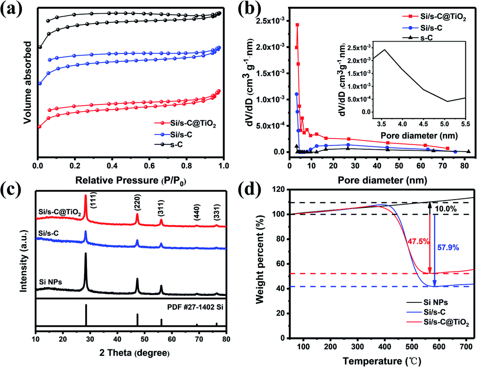
The specific surface area and pore size distribution of the silicon-free spherical carbon (s-C), Si/s-C and Si/s-C@TiO2 composites were characterized by the BET and BJH methods, respectively. It is obvious that nitrogen sorption isotherms of all the three samples exhibited typical IV curves with distinct H4 hysteresis loops with a fairly high adsorption capacity in the low-pressure range (Fig. 2a), implying the presence of a large number of microporous and mesopores in these samples, which was also confirmed by the relevant pore size distribution (Fig. 2b). The pore size distribution of Si/s-C@TiO2 showed a peak at around 3.6 nm (Fig. 2b inset), and the number of pores under this aperture is much more than spherical carbon (s-C) and Si/s-C. These mesopores accelerate Li+ and electron transport and relieve stress, thus improving electrochemical performance.40 Moreover, probably owing to the surface coating of TiO2, relative to the specific surface area of 285.6 m2 g−1 of Si/s-C composite, the specific surface area of Si/s-C@TiO2 composite was just 245.1 m2 g−1, which helped to improve the initial coulomb efficiency (CE) (Table S2†).41 The XRD patterns are shown in Fig. 2c to determine the phase changes of the composites during the preparation process. The diffraction peaks of 28.4°, 47.3°, 56.1°, 69.1° and 76.5° coordinated well with the highly crystalline Si (JCPDS card No. 27-1402) of (111), (220), (311), (440) and (331). And these showed that Si nanoparticles in Si/s-C@TiO2 composites and Si/s-C composites remain in its crystalline state after thermal and treatments. No diffraction peaks corresponding to TiO2 and graphitic carbon were observed in the XRD pattern, implying that the TiO2 and spherical carbon in the composites appeared as amorphous states. Fig. 2d shows the thermogravimetric (TG) curves of the composite. And the Si content of the sample was determined by burning the carbon matrix in the composite in air. Due to the partial oxidation of Si NPs, the weight of bare silicon samples increased by 10.0 wt%. The carbon content of Si/s-C and Si/s-C@TiO2 composites were about 67.9 wt% and 57.5 wt%, observed by the TG characterization, respectively. Therefore, the silicon content of Si/s-C composite was determined to be 32.1%. Since Si/s-C@TiO2 composite was ready on the basis of Si/s-C composite, they have a similar mass proportion of silicon to carbon. The silicon content of the Si/s-C@TiO2 composite was then calculated from the following equation:

 | ||
| Fig. 2 (a) N2 adsorption–desorption isotherms for s-C, Si/s-C, and Si/s-C@TiO2. (b) Relevant BJH pore size distribution (inset: magnified plot of Si/s-C@TiO2); (c) XRD patterns of the three samples above; (d) TG curves of the three samples above from 50 °C to 730 °C in air. | ||
The chemical composition of the Si/s-C@TiO2 composites was further determined by XPS characterization. The comparison of the XPS survey spectra of the Si NPs and Si/s-C@TiO2 composites is shown in Fig. 3a. Relative to the survey spectra of Si NPs, the survey spectra of Si/s-C@TiO2 composites presented an obvious Ti 2p peak at 457.95 eV. While the C 1s peak increased greatly, the Si 2S and Si 2p peaks decreased greatly. Since XPS is a surface analysis test characterization, it showed that silicon nanoparticles were well embedded in spherical carbon, and there was TiO2 protective layer on the outer surface. In addition, the corresponding element content of the Si/s-C@TiO2 composites by XPS is shown in Table S3.† The Fig. 3b shows the high-resolution spectrum of Ti 2p. The peaks at 459.38 eV and 465.06 eV correspond to Ti 2p 3/2 and Ti 2p 1/2 respectively, and the peak spacing of 5.70 eV also indicates that titanium was present as Ti4+ in TiO2.37 The high-resolution Si 2p and O 1s spectrum are shown in Fig. S3.† The peak at 99.74 eV in the high-resolution Si 2p spectrum corresponded to Si, while the peak at 103.10 eV corresponded to SiO2, probably due to the natural SiO2 layer produced on the surface of the Si nanoparticles by exposure to air. The peaks at 532.68 eV and 530.71 eV in the high-resolution O 1s spectra corresponded to SiO2 and TiO2 respectively, again confirming the presence of SiO2 and TiO2 layers on the surface of the Si/s-C@TiO2 composites.
 | ||
| Fig. 3 (a) XPS survey spectra of Si NPs and Si/s-C@TiO2 composites; (b) high resolution XPS spectra of Ti 2p. | ||
To assess the lithium storage characteristics of Si/s-C@TiO2 composite, a series of electrochemical tests were performed. The lithium/delithium performance of the electrodes were first tested by CV to characterise the discharge/charge process of the electrodes. The primary discharge processes (Si-alloying) of the Si/s-C@TiO2 (Fig. 4a) showed the broad cathode peak at <0.7 V and the sharp peak beneath 0.1 V, corresponding to the construction of the SEI layer and the alloying of crystalline silicon and lithium during first lithium insertion process, respectively. And it was also observed that in the latter cycle there was not only a peak at <0.1 V but also an additional characteristic peak at ∼0.2 V, which was due to the phase transition of silicon from the crystalline to the amorphous state after the Initial alloying reaction. Accordingly, two distinct anode peaks appeared near 0.31 V and 0.48 V during charging, derived from the transformation of LixSi de-alloying to amorphous silicon, which is similar to those previously reported.42,43 More significantly, there was an exceptional anode peak at 1.40 V (Fig. 3a inset) that appeared in the initial discharge scan was originated from the irreversible phase transition from the amorphous TiO2 to Li2Ti2O4, which again confirmed the existence of amorphous TiO2 shell. And the amorphous TiO2 shell produces lower diffusion resistance and faster transport of lithium ions compared to crystalline TiO2.37 Cyclic voltammetry measurements were also performed on bare Si NPs electrodes for comparison purposes (Fig. 4b). After the first cycle, the cathode peak on the discharge cycle curve shifted significantly to the left, which can be made sense of by the larger polarisation of the Si NPs electrodes, resulting in poor reversible stability. Anyway, the CV curves of the Si/s-C@TiO2 electrode were not significantly shifted after the first cycle and the peak intensity was more stable, indicating enhanced cyclic performance in the subsequent cycles.44
 | ||
| Fig. 4 Cyclic voltammetry curves for the first five cycles of (a) Si/s-C@TiO2 and (b) Si NPs (inset: enlargements of indicated voltage ranges). | ||
Fig. 5a shows the charging and discharging curves of Si/s-C@TiO2 composite after different number of cycles (100 mA g−1 for the initial cycle and 200 mA g−1 for 2nd to 100th cycles). A plateau of <0.7 V was evident in the initial discharge curve and vanished in the following cycles, which was related to the generation of the SEI layer on the electrode and was consistent with the CV results. The long plateau of about 0.1 V corresponded to the alloying reaction of crystalline silicon with Li+, which was shifted to about 0.25 V in the following cycles because of the higher working potential of amorphous silicon. The initial discharge and charge capacities of the Si/s-C@TiO2 composite were 1805 mA h g−1 and 1145 mA h g−1, respectively, and its coulombic efficiency was 63.4%. Large irreversible capacity loss in the initial charge/discharge, which was related to the construction of the SEI layer and the trapping of excess Li+ by spherical carbon with large specific surface area during the first lithium insertion process, which was associated with the spherical carbon with a well-developed pore structure.45 This was evidenced by the first charge and discharge process of pure spherical carbon (Fig. S4†). After the initial discharge of Si/s-C@TiO2, the charge/discharge curves afterwards were highly overlapping, indicating a critical decrease of its irreversible capacity as well as the stability of the SEI layer. Fig. 5b exhibits the comparison of the cycling stability of commercial Si NPs anode and Si/s-C@TiO2 composite. Commercial Si NPs anode showed severe capacity degradation during cycling, with a secondary discharge capacity retention rate of just 10.8% after 100 cycles, resulting in a final specific capacity of 219 mA h g−1. Furthermore, it was achieved with a new sodium carboxymethyl cellulose binder, which is considered to be a good binder for Si anodes.46 In contrast, the reversible capacity of the Si/s-C@TiO2 electrode was increased to 780 mA h g−1 with a secondary discharge specific capacity retention of 83.1% after 100 cycles. In addition, the coulomb efficiency of the electrode reached 98% in the fourth cycle and remained more than 98% in the following cycles. The excellent coulombic efficiency and cycling stability could be abstracted as the following excellent characteristics: (1) the spherical carbon provided a high-speed conductive channel for the Si NPs, making most Si NPs electrochemically active; (2) the encapsulated carbon matrix buffered the severe volume expansion of the Si NPs, allowing the main SEI layer to be generated on the external surface of the composite rather than on the surface of the Si NPs, consequently guaranteeing the integrity and steadiness of the electrode structure and SEI layer; (3) the strong mechanical strength of the TiO2 shell layer further ensured the stability of the SEI layer on the outer surface of the electrode. Furthermore, the Si/s-C@TiO2 electrode exhibited excellent rate performance. As displayed in Fig. 5c, it achieved reversible capacities of 898 mA h g−1, 807 mA h g−1, 681 mA h g−1, and 588 mA h g−1 at 0.2 A g−1, 0.4 A g−1, 1.6 A g−1, and 3.2 A g−1, respectively, significantly greater than the Si/s-C electrode without the TiO2 shell coating. Additionally, once the current density had finally returned to 0.2 A g−1, the capacity of the Si/s-C@TiO2 composite could reach 776 mA h g−1 in the 50th cycle (86% of the first segment), indicating full recovery and stability in the following cycles. This outstanding rate performance was credited to the large specific surface area and mesoporous structure, which ensured complete penetration of the active substance and high conductivity of electrons and Li+. In order to reveal the importance of spherical carbon and TiO2 shell in Si/s-C@TiO2 composites, cycling tests were carried out using the same current density for two electrodes-TiO2 directly encapsulated Si NPs (Si@TiO2) and a spherical carbon encapsulated silicon–carbon composite without TiO2 shell (Si/s-C) (Fig. 5d). It could be noticed that the specific capacity of Si@TiO2 dropped significantly after few cycles owing to the lack of the conductive matrix and volume buffer provided by the carbon matrix. Meanwhile, relative to 83.1% capacity retention of Si/s-C@TiO2 electrode, the Si/s-C electrode achieved a capacity retention of 61.3% after 100 cycles, mainly attributed to the somewhat low CE in the initial 20 cycles. It indicated that the presence of TiO2 layer helped the generation of electrode stabilized SEI layer.
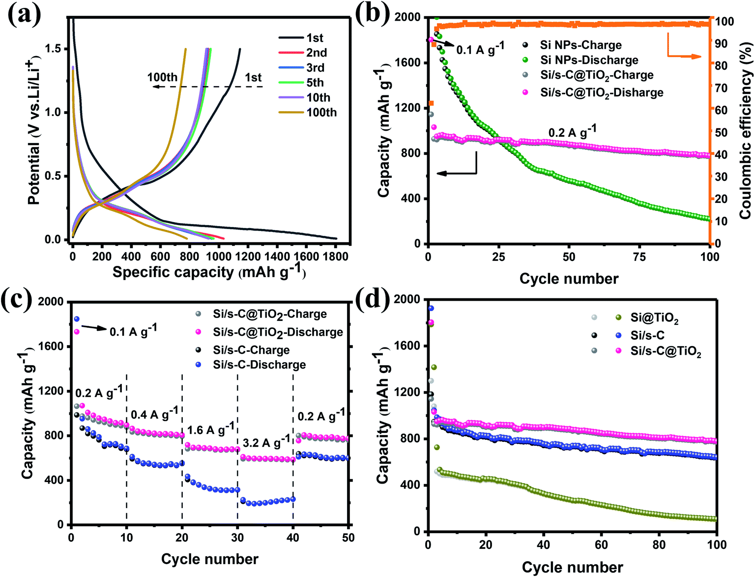 | ||
| Fig. 5 (a) Charge and discharge voltage profiles of Si/s-C@TiO2 composite for the 1st, 2nd, 3rd, 5th, 10th and 100th cycles; (b) cycling stability for Si/s-C@TiO2 composite compared to commercial Si NPs at 0.2 A g−1 and (c) rate performance of Si/s-C and Si/s-C@TiO2 at 0.2 A g−1, 0.4 A g−1,1.6 A g−1,3.2 A g−1 and 0.2 A g−1. (d) cycling test for Si/s-C@TiO2 compared to Si/s-C and Si@TiO2 electrodes at 0.2 A g−1. | ||
The charge transfer kinetics of the Si/s-C@TiO2 as well as the Si/s-C and Si NPs electrode were studied by EIS. Fig. 6a demonstrates the Nyquist plots of Si/sC@TiO2, Si/s-C and Si NPs electrodes before cycling. The semicircle in the high frequency region is caused by the interfacial charge transfer resistance,47–49 and the corresponding fitted values were listed in Table S4.† It could be seen that the unactivated Si/sC@TiO2 composite had the highest Rct, which was related to the low electrical conductivity of TiO2. The slope line in the low frequency region was related to the diffusion behaviour of Li+ in the electrode. From Fig. 6b, it could be seen that the slopes of the Si/s-C and Si/s-C@TiO2 composites were below the Si NPs, demonstrating facile diffusion kinetics of lithium ions in electrode,50 which was due to the rich mesoporous structure of the spherical carbon. After 100 cycles, Nyquist curves were further obtained to assess the condition of the electrodes after cycling. As shown in Fig. 6c, the Nyquist plot after 100 cycles had two additional semicircles in the high frequency region and low frequency region, which were derived from the current conductance behaviour at the transition between electrode and current collector and the construction of the SEI layer, respectively.51 It was significant that the Si/s-C@TiO2 composite demonstrated the lowest charge transfer resistance (Rct) value of 17.53 Ω in contrast to the high Rct in the initial state, which was due to the excellent conductive substrate originated from the spherical carbon and activated TiO2 shell. For the Si/sC@TiO2 electrode, the Nyquist plots were almost overlapped during cycling, indicating that the impedance induced by the SEI layer remained essentially unchanged or even decreased to some extent, indicating the construction of a stable and thin SEI layer (Fig. 6d).
 | ||
| Fig. 6 (a) Nyquist plots of the Si NPs, Si/s-C and Si/s-C@TiO2 composites in fresh state and the equivalent circuit model used for fitting; (b) corresponding liner fits (relationship between Z′ and ω−1/2) in low-frequency region originated from Fig. 5 (a); (c) Nyquist plots of the three electrodes above after 100 cycles, and (d) the Nyquist plots of the Si/s-C@TiO2 composite after different cycles. | ||
XPS surface test analysis of post-cycled Si NPs and Si/s-C@TiO2 electrodes was carried out to show the specifics of the SEI layer on the electrode surface after cycling. Fig. 7 showed the high-resolution C 1s, O 1s, f 1s, Si 2p, Li 1s and Ti 2p spectra after 100 cycles. In the C 1s spectrum of Fig. 7a, the peak at 284.80 eV was the C–C bond, which was due to hydrocarbon contamination of the surface. The peak at 286.26 eV was due to residues of the ether used to clean the electrodes. The peaks at 288.15 eV and 289.59 eV represented carbonaceous substances such as O![[double bond, length as m-dash]](https://www.rsc.org/images/entities/char_e001.gif) C–O, CO3, which were the main components of the SEI layer.52 These peaks may also be from the sodium carboxymethyl cellulose used as the binder. Fig. 7b represented the F 1s spectrum of the electrodes after cycling. The peak at 685.32 eV marked the presence of LiF and the intensity of the LiF peak on the Si/s-C@TiO2 electrode was much greater than that of the Si NPs electrode. While the peak at 687.72 eV indicated LixPFy, which was obtained from the decomposition of LiPF6 in the electrode solution. The presence of LiF in the Si/s-C@TiO2 electrode after cycling was also confirmed by the peak at 55.72 eV in the Fig. 7c Li 1s spectrum. The peak at 55.06 eV in Fig. 7c Li 1s spectrum and the peak at 531.57 eV in Fig. 7d O 1s spectrum confirmed the existence of Li2CO3 in the cycled Si NPs electrode. The peak at 532.40 eV in Fig. 7d O 1s spectrum corresponded to the Si–O bond, which indicated that the naturally oxidised SiO2 layer is still present on the Si surface in the electrode cycling. The peak at 102.52 eV in Fig. 7e Si 2p spectrum corresponded to the substance LixSiOy, which was an important component of the SEI film, indicating the presence of a dense SEI layer on the surface of the electrode, similar to a metal oxide coating, which improves the alloying reaction of silicon with lithium.53 As can be seen from Fig. 7f Ti 2p spectra, there were no obvious peaks of elemental Ti on the surface of the Si/s-C@TiO2 electrode after cycling. This was because elemental Ti will no longer be observed by XPS after cycling when the electrode surface was covered with SEI film. As shown above, the cycled Si/s-C@TiO2 composite electrode exhibited a large amount of LiF, which has been reported by a large number of researchers to be associated with the SEI film that enhances the cycling stability of the silicon anode, and the high concentration of LiF may also be associated with the FEC additive added to the electrolyte.54,55 In contrast, the Si NPs electrode after cycling exhibited a very weak LiF signal, which was replaced by a higher Li2CO3 signal, also an important component of the SEI layer, which was more stable chemically and easier to form. The lower LiF signal may be due to the huge volume expansion of the Si NPs, which made it difficult to stabilise the LiF. In addition, Fig. S5† showed XPS survey spectra of two electrodes after cycling. In addition to the F 1s, O 1s, C 1s, Si 2p and Li 1s spectra mentioned above, peaks for P 2s, P 2p and Na 2s were also observed, which were attributed to the LixPFy produced by the decomposition of the electrolyte and the binder sodium carboxymethyl cellulose, respectively.
C–O, CO3, which were the main components of the SEI layer.52 These peaks may also be from the sodium carboxymethyl cellulose used as the binder. Fig. 7b represented the F 1s spectrum of the electrodes after cycling. The peak at 685.32 eV marked the presence of LiF and the intensity of the LiF peak on the Si/s-C@TiO2 electrode was much greater than that of the Si NPs electrode. While the peak at 687.72 eV indicated LixPFy, which was obtained from the decomposition of LiPF6 in the electrode solution. The presence of LiF in the Si/s-C@TiO2 electrode after cycling was also confirmed by the peak at 55.72 eV in the Fig. 7c Li 1s spectrum. The peak at 55.06 eV in Fig. 7c Li 1s spectrum and the peak at 531.57 eV in Fig. 7d O 1s spectrum confirmed the existence of Li2CO3 in the cycled Si NPs electrode. The peak at 532.40 eV in Fig. 7d O 1s spectrum corresponded to the Si–O bond, which indicated that the naturally oxidised SiO2 layer is still present on the Si surface in the electrode cycling. The peak at 102.52 eV in Fig. 7e Si 2p spectrum corresponded to the substance LixSiOy, which was an important component of the SEI film, indicating the presence of a dense SEI layer on the surface of the electrode, similar to a metal oxide coating, which improves the alloying reaction of silicon with lithium.53 As can be seen from Fig. 7f Ti 2p spectra, there were no obvious peaks of elemental Ti on the surface of the Si/s-C@TiO2 electrode after cycling. This was because elemental Ti will no longer be observed by XPS after cycling when the electrode surface was covered with SEI film. As shown above, the cycled Si/s-C@TiO2 composite electrode exhibited a large amount of LiF, which has been reported by a large number of researchers to be associated with the SEI film that enhances the cycling stability of the silicon anode, and the high concentration of LiF may also be associated with the FEC additive added to the electrolyte.54,55 In contrast, the Si NPs electrode after cycling exhibited a very weak LiF signal, which was replaced by a higher Li2CO3 signal, also an important component of the SEI layer, which was more stable chemically and easier to form. The lower LiF signal may be due to the huge volume expansion of the Si NPs, which made it difficult to stabilise the LiF. In addition, Fig. S5† showed XPS survey spectra of two electrodes after cycling. In addition to the F 1s, O 1s, C 1s, Si 2p and Li 1s spectra mentioned above, peaks for P 2s, P 2p and Na 2s were also observed, which were attributed to the LixPFy produced by the decomposition of the electrolyte and the binder sodium carboxymethyl cellulose, respectively.
 | ||
| Fig. 7 High resolution XPS spectra of (a) C 1s, (b) F 1s, (c) Li 1s, (d) O1s, (e) Si 2p and (f) Ti 2p of Si NPs and Si/s-C@TiO2 after 100 cycles. | ||
To further understand the enhanced cyclic stability of electrodes, SEM tests were carried out on three electrodes before and after 100 cycles to verify the connection between stable structure and cycling stability of the electrodes. As shown in Fig. 8a–c, the surface of all the three electrodes were flat and compact at the fresh state. After 100 cycles, as displayed in the Fig. 8f, the Si/s-C@TiO2 electrode retained its original structure after cycling with no significant morphological damage, which was owing to the rigid TiO2 layer in the coating and spherical carbon to buffer the expansion of active Si NPs, which greatly supported the stability of the structure. However, in the absence of a TiO2 layer, the Si/s-C composite demonstrated a certain degree of pulverization after 100 cycles due to volume effect, as displayed in Fig. 8e. In addition, the pure Si NPs anode showed significant fracture after cycling (Fig. 8d), which might be brought about by uncontrollable volume expansion. Moreover, the surface of the Si/s-C@TiO2 electrode after cycling was covered with a stable SEI layer confirmed by the region in the circle in Fig. 8f, further demonstrating the stability of the structure during cycling.56 SEM images of Si/s-C@TiO2 electrode in the delithiated state before and after 1000 cycles were further taken. As shown in Fig. S6,† the surface of the Si/s-C@TiO2 electrode before cycling appeared porous due to the support of the spherical carbon. While after cycling, the surface of the electrode presented a dense state due to a certain volume expansion and the coverage of the surface SEI film, but there were no obvious cracks. As can be seen from the enlarged view in the inset, the spherical state of the Si/s-C@TiO2 nanostructure still appeared to remain intact after 1000 cycles, and the stable SEI film covering the surface can be seen. These further demonstrated the stability of the Si/s-C@TiO2 electrode structure.
 | ||
| Fig. 8 SEM images of (a) Si NPs, (b) Si/s-C and (c) Si/s-C@TiO2 before cycling; SEM images of (d) Si NPs, (e) Si/s-C and (f) Si/s-C@TiO2 after 100 cycles. | ||
4. Conclusions
In conclusion, a hydrothermal method using low-cost glucose as a precursor to carbon was utilized to achieve spherical carbon encapsulation of commercial silicon nanoparticles, which enhanced the electrical conductivity while buffering the expansion of Si NPs during the discharging and charging process. In addition, a thin amorphous TiO2 layer was covered on the outer surface of the composite electrode, forming a stable SEI layer on the external surface of the electrode, which further improved the cycling stability of the composite electrode. Based on such a structural design, the new Si/s-C@TiO2 composite exhibited 780 mA h g−1 after 100 cycles at a current density of 0.2 A g−1 with a coulombic efficiency of 99%. Such performance was at the forefront compared to those of other reports for the protection of Si NPs (Table S5†). In a word, our dual protection strategy provides good results for structural optimization of silicon negative electrodes, but also it provides insights for improving other potential electrode materials with inhibiting their large volume variations of the counterparts.Conflicts of interest
There are no conflicts to declare.Acknowledgements
We are grateful for the financial support from the cooperation project of Sichuan University with Sichuan Qingquan Technology Company (18H0691) and the funds of Sichuan University.Notes and references
- Y. Liu, P. He and H. Zhou, Adv. Energy Mater., 2018, 8, 1701602 CrossRef.
- G. Zhou, A. Yang, G. Gao, X. Yu, J. Xu, C. Liu, Y. Ye, A. Pei, Y. Wu and Y. Peng, Sci. Adv., 2020, 6, eaay5098 CrossRef CAS PubMed.
- Z. Lu, N. Liu, H.-W. Lee, J. Zhao, W. Li, Y. Li and Y. Cui, ACS Nano, 2015, 9, 2540–2547 CrossRef CAS PubMed.
- D.-H. Liu, Z. Bai, M. Li, A. Yu, D. Luo, W. Liu, L. Yang, J. Lu, K. Amine and Z. Chen, Chem. Soc. Rev., 2020, 49, 5407–5445 RSC.
- H. Chen, R. Ren, M. Wei and W. Chu, Ionics, 2020, 26, 6013–6022 CrossRef CAS.
- J. Li, N. Wang, J. Deng, W. Qian and W. Chu, J. Mater. Chem. A, 2018, 6, 13012–13020 RSC.
- J. Deng, Y. Dai, H. Dai and L. Li, Appl. Sci., 2020, 10, 2220 CrossRef CAS.
- C. K. Chan, H. Peng, G. Liu, K. McIlwrath, X. F. Zhang, R. A. Huggins and Y. Cui, Nat. Nanotechnol., 2008, 3, 31–35 CrossRef CAS PubMed.
- M. Obrovac, L. Christensen, D. B. Le and J. R. Dahn, J. Electrochem. Soc., 2007, 154, A849 CrossRef CAS.
- W.-J. Zhang, J. Power Sources, 2011, 196, 13–24 CrossRef CAS.
- H. Wu, G. Zheng, N. Liu, T. J. Carney, Y. Yang and Y. Cui, Nano Lett., 2012, 12, 904–909 CrossRef CAS PubMed.
- L. Beaulieu, K. Eberman, R. Turner, L. Krause and J. Dahn, Electrochem. Solid-State Lett., 2001, 4, A137 CrossRef CAS.
- P. Raimann, N. Hochgatterer, C. Korepp, K.-C. Möller, M. Winter, H. Schröttner, F. Hofer and J. Besenhard, Ionics, 2006, 12, 253–255 CrossRef CAS.
- X.-W. Zhang, P. K. Patil, C. Wang, A. J. Appleby, F. E. Little and D. L. Cocke, J. Power Sources, 2004, 125, 206–213 CrossRef CAS.
- N. Liu, H. Wu, M. T. McDowell, Y. Yao, C. Wang and Y. Cui, Nano Lett., 2012, 12, 3315–3321 CrossRef CAS PubMed.
- Y. Jin, S. Li, A. Kushima, X. Zheng, Y. Sun, J. Xie, J. Sun, W. Xue, G. Zhou and J. Wu, Energy Environ. Sci., 2017, 10, 580–592 RSC.
- J. Guo, D. Dong, J. Wang, D. Liu, X. Yu, Y. Zheng, Z. Wen, W. Lei, Y. Deng and J. Wang, Adv. Funct. Mater., 2021, 2102546 CrossRef CAS.
- P. Li, H. Kim, S.-T. Myung and Y.-K. Sun, Energy Storage Mater., 2021, 35, 550–576 CrossRef.
- T. H. Hwang, Y. M. Lee, B.-S. Kong, J.-S. Seo and J. W. Choi, Nano Lett., 2012, 12, 802–807 CrossRef CAS PubMed.
- Y. Oumellal, N. Delpuech, D. Mazouzi, N. Dupre, J. Gaubicher, P. Moreau, P. Soudan, B. Lestriez and D. Guyomard, J. Mater. Chem., 2011, 21, 6201–6208 RSC.
- M. Scagliotti, M. Salvato, F. Frezza, D. Catone, L. Di Mario, M. Boscardin, M. De Crescenzi and P. Castrucci, Appl. Sci., 2021, 11, 606 CrossRef CAS.
- M.-H. Park, M. G. Kim, J. Joo, K. Kim, J. Kim, S. Ahn, Y. Cui and J. Cho, Nano Lett., 2009, 9, 3844–3847 CrossRef CAS PubMed.
- F. H. Du, B. Li, W. Fu, Y. J. Xiong, K. X. Wang and J. S. Chen, Adv. Mater., 2014, 26, 6145–6150 CrossRef CAS PubMed.
- H. Ma, F. Cheng, J. Y. Chen, J. Z. Zhao, C. S. Li, Z. L. Tao and J. Liang, Adv. Mater., 2007, 19, 4067–4070 CrossRef CAS.
- H. Wu and Y. Cui, Nano today, 2012, 7, 414–429 CrossRef CAS.
- F. M. Hassan, R. Batmaz, J. Li, X. Wang, X. Xiao, A. Yu and Z. Chen, Nat. Commun., 2015, 6, 1–11 Search PubMed.
- J. Chang, X. Huang, G. Zhou, S. Cui, P. B. Hallac, J. Jiang, P. T. Hurley and J. Chen, Adv. Mater., 2014, 26, 758–764 CrossRef CAS PubMed.
- N. Kim, S. Chae, J. Ma, M. Ko and J. Cho, Nat. Commun., 2017, 8, 1–10 CrossRef CAS PubMed.
- S. Jeong, J.-P. Lee, M. Ko, G. Kim, S. Park and J. Cho, Nano Lett., 2013, 13, 3403–3407 CrossRef CAS PubMed.
- M. Ko, S. Chae, J. Ma, N. Kim, H.-W. Lee, Y. Cui and J. Cho, Nat. Energy, 2016, 1, 1–8 Search PubMed.
- T. Shen, X.-h. Xia, D. Xie, Z.-j. Yao, Y. Zhong, J.-y. Zhan, D.-h. Wang, J.-b. Wu, X.-l. Wang and J.-p. Tu, J. Mater. Chem. A, 2017, 5, 11197–11203 RSC.
- N. Liu, Z. Lu, J. Zhao, M. T. McDowell, H.-W. Lee, W. Zhao and Y. Cui, Nat. Nanotechnol., 2014, 9, 187–192 CrossRef CAS PubMed.
- J. Liu, S. Z. Qiao, H. Liu, J. Chen, A. Orpe, D. Zhao and G. Q. Lu, Angew. Chem., 2011, 123, 6069–6073 CrossRef.
- G. He, S. Evers, X. Liang, M. Cuisinier, A. Garsuch and L. F. Nazar, ACS Nano, 2013, 7, 10920–10930 CrossRef CAS PubMed.
- H. Jia, P. Gao, J. Yang, J. Wang, Y. Nuli and Z. Yang, Adv. Energy Mater., 2011, 1, 1036–1039 CrossRef CAS.
- W. Luo, Y. Wang, L. Wang, W. Jiang, S.-L. Chou, S. X. Dou, H. K. Liu and J. Yang, ACS Nano, 2016, 10, 10524–10532 CrossRef CAS PubMed.
- J. Yang, Y. Wang, W. Li, L. Wang, Y. Fan, W. Jiang, W. Luo, Y. Wang, B. Kong and C. Selomulya, Adv. Mater., 2017, 29, 1700523 CrossRef PubMed.
- D. Xu, W. Chen, Y. Luo, H. Wei, C. Yang, X. Cai, Y. Fang and X. Yu, Appl. Surf. Sci., 2019, 479, 980–988 CrossRef CAS.
- Y. Jin, S. Li, A. Kushima, X. Q. Zheng, Y. M. Sun, J. Xie, J. Sun, W. J. Xue, G. M. Zhou, J. Wu, F. F. Shi, R. F. Zhang, Z. Zhu, K. P. So, Y. Cui and J. Li, Energy Environ. Sci., 2017, 10, 580–592 RSC.
- C. Xiao, N. Du, X. Shi, H. Zhang and D. Yang, J. Mater. Chem. A, 2014, 2, 20494–20499 RSC.
- S. Guo, X. Hu, Y. Hou and Z. Wen, ACS Appl. Mater. Interfaces, 2017, 9, 42084–42092 CrossRef CAS PubMed.
- Y. Zhang, N. Du, Y. Chen, Y. Lin, J. Jiang, Y. He, Y. Lei and D. Yang, Nanoscale, 2018, 10, 5626–5633 RSC.
- R. Yi, F. Dai, M. L. Gordin, S. Chen and D. Wang, Adv. Energy Mater., 2013, 3, 295–300 CrossRef CAS.
- D. Shao, D. Tang, Y. Mai and L. Zhang, J. Mater. Chem. A, 2013, 1, 15068–15075 RSC.
- Z.-L. Xu, Y. Gang, M. A. Garakani, S. Abouali, J.-Q. Huang and J.-K. Kim, J. Mater. Chem. A, 2016, 4, 6098–6106 RSC.
- S. Komaba, K. Shimomura, N. Yabuuchi, T. Ozeki, H. Yui and K. Konno, J. Phys. Chem. C, 2011, 115, 13487–13495 CrossRef CAS.
- L. Shi, W. Wang, A. Wang, K. Yuan, Z. Jin and Y. Yang, J. Mater. Chem. A, 2015, 3, 18190–18197 RSC.
- W. Ren, Y. Wang, Z. Zhang, Q. Tan, Z. Zhong and F. Su, J. Mater. Chem. A, 2016, 4, 552–560 RSC.
- D. Xie, D. Wang, W. Tang, X. Xia, Y. Zhang, X. Wang, C. Gu and J. Tu, J. Power Sources, 2016, 307, 510–518 CrossRef CAS.
- B. Li, W. Zhao, Z. Yang, C. Zhang, F. Dang, Y. Liu, F. Jin and X. Chen, J. Power Sources, 2020, 466, 228339 CrossRef CAS.
- M. Steinhauer, S. Risse, N. Wagner and K. A. Friedrich, Electrochim. Acta, 2017, 228, 652–658 CrossRef CAS.
- J. John, B. Gangaja, S. V. Nair and D. Santhanagopalan, Electrochim. Acta, 2017, 235, 191–199 CrossRef CAS.
- J. Kim, O. B. Chae and B. L. Lucht, J. Electrochem. Soc., 2021, 168, 030521 CrossRef CAS.
- E. Markevich, G. Salitra, F. Chesneau, M. Schmidt and D. Aurbach, ACS Energy Lett., 2017, 2, 1321–1326 CrossRef CAS.
- E. Markevich, K. Fridman, R. Sharabi, R. Elazari, G. Salitra, H. Gottlieb, G. Gershinsky, A. Garsuch, G. Semrau and M. Schmidt, J. Electrochem. Soc., 2013, 160, A1824 CrossRef CAS.
- Z. Yi, N. Lin, T. Xu and Y. Qian, Chem. Eng. J., 2018, 347, 214–222 CrossRef CAS.
Footnote |
| † Electronic supplementary information (ESI) available. See https://doi.org/10.1039/d2ra02007f |
| This journal is © The Royal Society of Chemistry 2022 |