
 Open Access Article
 This Open Access Article is licensed under a Creative Commons Attribution-Non Commercial 3.0 Unported Licence
Rational design of large flat nitrogen-doped graphene oxide quantum dots with green-luminescence suitable for biomedical applications
Michael Nazarkovskya,
Albina Mikhraliieva a,
Carlos A. Acheteb,
Luiz Anastacio Alvesc,
Joyce Araujob,
Bráulio S. Archanjob,
José Júnior França de Barrosd,
Liana Monteiro da Fonseca Cardosoc,
José Nelson S. S. Couceiroe,
Fernanda Davi Marquesb,
Bruno S. Oliveirab,
Rafael Nascimento Dias de Souzab,
Ayla Josma Teixeirac,
Thiago L. Vasconcelosb and
Vladimir Zaitsev*af
a,
Carlos A. Acheteb,
Luiz Anastacio Alvesc,
Joyce Araujob,
Bráulio S. Archanjob,
José Júnior França de Barrosd,
Liana Monteiro da Fonseca Cardosoc,
José Nelson S. S. Couceiroe,
Fernanda Davi Marquesb,
Bruno S. Oliveirab,
Rafael Nascimento Dias de Souzab,
Ayla Josma Teixeirac,
Thiago L. Vasconcelosb and
Vladimir Zaitsev*af
aDepartment of Chemistry, Pontifical Catholic University of Rio de Janeiro, Marques de Sao Vicente, 225, 22451-900, Rio de Janeiro, Brazil
bInstituto Nacional de Metrologia, Qualidade e Tecnologia, Inmetro, Av. Nossa Senhora das Graças, 50, Xerém, Duque de Caxias, 25250-020, Brazil
cLaboratory of Cellular Communication, Oswaldo Cruz Institute, Oswaldo Cruz Foundation, 4365 Manguinhos, Rio de Janeiro 21045-900, Brazil
dLaboratório de Virologia Molecular-LVM-IOC/FIOCRUZ/Rio de Janeiro-RJ-Brasil, CEP 21041-210, Brazil
eInstituto de Microbiologia Paulo de Góes, Universidade Federal do Rio de Janeiro, Rio de Janeiro, RJ 21941-902, Brazil
fNational University of Kyiv-Mohyla Academy, 2 Skovorody Vul., Kyiv, 04070, Ukraine. E-mail: v.zaytsev@ukma.edu.ua
First published on 12th May 2022
Abstract
Rational synthesis and simple methodology for the purification of large (35–45 nm in lateral size) and flat (1.0–1.5 nm of height) nitrogen-doped graphene oxide quantum dots (GOQDs) are presented. The methodology allows robust metal-free and acid-free preparation of N-GOQDs with a yield of about 100% and includes hydrothermal treatment of graphene oxide with hydrogen peroxide and ammonia. It was demonstrated that macroscopic impurities can be separated from N-GOQD suspension by their coagulation with 0.9% NaCl solution. Redispersible in water and saline solutions, particles of N-GOQDs were characterized using tip-enhanced Raman spectroscopy (TERS), photoluminescent, XPS, and UV-VIS spectroscopies. The size and morphology of N-GOQDs were studied by dynamic light scattering, AFM, SEM, and TEM. The procedure proposed allows nitrogen-doped GOQDs to be obtained, having 60–51% of carbon, 34–45% of oxygen, and up to 7.2% of nitrogen. The N-GOQD particles obtained in two hours of synthesis contain only pyrrolic defects of the graphene core. The fraction of pyridine moieties grows with the time of synthesis, while the fraction of quaternary nitrogen declines. Application of TERS allows demonstration that the N-GOQDs consist of a graphene core with an average crystallite size of 9 nm and an average distance between nearest defects smaller than 3 nm. The cytotoxicity tests reveal high viability of the monkey epithelial kidney cells Vero in the presence of N-GOQDs in a concentration below 60 mg L−1. The N-GOQDs demonstrate green luminescence with an emission maximum at 505 nm and sedimentation stability in the cell culture medium.
1 Introduction
Carbon dots (CDs) is a general term that is currently used for a new class of carbonaceous fluorescent nanoscale objects1–3 that was discovered in 2004 by the electrophoretic purification of oxidized single-wall carbon nanotubes.4 CDs demonstrate photoluminescence (PL) not seen for earlier known fullerenes and nanodiamonds, can be obtained from various carbon-containing precursors in gram-scale,5 and can produce stable suspensions in water. Unlike other photoluminescent nano-objects such as porous silicon,6 metal halide perovskite nanocrystals,7 and semiconductor quantum dots, CDs are metal-free nano-objects and thus they are much more environmentally friendly and biocompatible. Finally, the production and application of CDs are very sustainable. They can be obtained from various organic objects,8 and degrade in a natural environment. Due to their low-toxic nature and biocompatibility CDs have great potential in biotechnology and nanomedicine,1,9,10 cell imaging and biolabeling,11–14 for drug release,15 theranostics,9,16 and photodynamic therapy.17CDs can be synthesized using a wide variety of top-down and bottom-up approaches. The top-down one is based on the shredding of large carbon objects such as graphite, graphene oxide,18 and nanodiamonds19 by using arc discharge,4 laser ablation,20 chemical or electrochemical oxidation.21 Bottom-up approach has been proposed more recently as an alternative to the top-down one.22–24 Due to facile preparation and promising characteristics, research on CDs has rapidly developed and in the last three years demonstrates high activity with more than 3000 publications per year (according to Scopus). It is obvious that such rapid development in CDs preparation methodology is accompanied by many errors and misconceptions and results even in nomenclature perplexity.25 Unclear mechanism of nanoparticle formation from molecular precursors stimulates speculative research on the synthesis of poorly characterized carbon nanodots (CNDs) from almost any organic compound.26–32 Commonly CNDs have small (1–5 nm) particle size and spherical topology, and no obvious graphene nature of the core.26,33 Contrary, chemistry of the nanoparticles synthesized from carbon macro objects is much clear.34 Such nanoparticles have an atomically thin graphitic plane (typically <2 nm thick) and much larger lateral dimensions.35,36 The bandgap of such nanoparticles is size-dependent,36 and therefore depending on oxygen content they have been called graphene quantum dots (GQDs) or graphene oxide quantum dots (GOQDs). Generally speaking, the top-down approaches facilitate the fabrication of GOQDs with high crystallinity and a relatively intact structure, while the bottom-up approach has resulted in a mixture of various CNDs.37
The biomedical application of CDs requires strict control of the particle size, chemical composition, and morphology.38 These characteristics determine the properties of the nanoparticles such as toxicity, permeability, and stability of the particle suspensions.39–42 For example, while large GOQDs particles have low cytotoxicity, small CNDs may have the potential of passing through the blood–brain barrier.43 Also it was demonstrated that CDs prepared in the bottom-up approach from bamboo demonstrate different cytotoxicity and cell permeability depending on the carbonization procedure.41 Since information on the composition and morphology of CNDs is much less intact it is more appropriate to use better-defined GOQDs for their biomedical application than poorly characterized CNDs.44,45
A general approach for the preparation of GOQDs is based on the shredding of different carbon-containing materials such as coal, carbon black, graphite, carbon fibers, fullerenes, etc. Exfoliated GO can be chemically shredded to GOQDs with good yield by W18O49, KMnO4, KHSO5, and KO2.2,12,46,47 Although powerful oxidants showed high efficiency, it is a tedious task to purify the nanoparticles for metal ion impurities,36 which may cause undesirable phenomena, such as lowered biocompatibility (in some cases, even toxicity), lowered luminescence efficiency or reduced ability as carriers of active substances.48,49 Therefore, sophisticated purification techniques are required for GOQDs purification.50
As an alternative to metal-containing oxidants, water solution of hydrogen peroxide was successfully texted in preparation of GOQDs from GO in the presence of iron ions.51 Most likely, GOQDs formation emerges from the process of GO radical epoxidation with further hydrolysis of oxirane cycles.52 Utilization of H2O2 in the GOQDs synthesis is a very desirable approach for their biomedical application since it enables the preparation of metal-free nanoparticles. Therefore, further attempts were performed to avoid the utilization of Fenton reaction. Particularly recently it was demonstrated that H2O2 can exfoliate GOQDs in the absence of metal ions under solvothermal conditions.53,54
Another important aspect in the preparation of GOQDs is their doping with heteroatoms. Doping of carbonaceous nanoparticles with heteroatoms, such as N, P, S, or B, is an effective way to modulate their chemical, electronic, and structural functionalities. Doping of GOQDs generates local defects in the graphene layer and thus delocalized charge.55 This charge can be a key factor determining cytotoxicity, cellular uptake, and intracellular trafficking of the nanoparticles.56 Among the different dopants, nitrogen-doped GOQDs (N-GOQDs) have garnered the most interest due to enhanced photoemission and tunable optical properties rendered by the three possible types of N-doping, including pyridinic N, pyrrolic N, and quaternary.57 Also N-GOQDs exhibit advantages such as good photothermal conversion efficiency and enhanced ability to generate singlet oxygen and superoxide radical anions58 that can be used in bioimaging and photodynamic therapy.59
Nitrogen doping can be performed through post-synthesis processes, for instance, in hydrothermally treating of GOQDs in ammonia solution. Alternatively, heteroatom doping can be achieved during the top-down synthesis of nanoparticles via introducing a heteroatom source or directly using dopant-containing oxidant or reductant.60
The current research is devoted to the one-step preparation of green-photoluminescent nitrogen-doped graphene oxide quantum dots (N-GOQDs) having 35 ± 10 nm in lateral size and 1–1.5 nm of height under hydrothermal treatment from graphene oxide in green metal-free and acid-free conditions with a yield of about 100%. For the preparation of N-doped GOQDs, the combination of H2O2 as an oxidizer and NH3 as a dopant seems to be a promising technique. It seems the presence of ammonium in the solution leads to the control of the oxidative potential of hydrogen peroxide and, thus, affects robust the yield of large N-GOQDs. The approach is suitable for the preparation of re-dispersible non-cytotoxic nanoparticles giving indefinitely stable suspensions in saline solution. One-step purification method that allows the separation of N-GOQDs from other carbonaceous residuals was also developed.
2 Materials and methods
2.1. Chemicals and equipment
Potassium permanganate (99%), Triton X-100, methylthiazolyldiphenyl-tetrazolium bromide (MTT), M199 media, dimethyl sulfoxide (DMSO), hydrogen peroxide (30%), and ammonia (33%) solutions were purchased from Sigma-Aldrich. Phosphoric acid (85%), sulfuric acid (95–98%), hydrochloric acid (37%), and sodium hydroxide (97%) were purchased from Vetec (Brazil), while graphite powder came from https://Synth.com.br (Brazil). Dialysis membrane (CE MWCO 8000–10![[thin space (1/6-em)]](https://www.rsc.org/images/entities/char_2009.gif) 000) from Spectra/Por® Biotech (USA), PTFE filters (0.45 μm) from Sartorius Stedim Biotech (Germany), and filters for syringes (PTFE-hydrophilic with polypropylene pre-filter, 0.22 μm) from Analitica (Brazil) were used for GO and N-GOQDs purification together with Amicon® stirred cell 50 mL (Sigma-Aldrich) and ultracentrifuge NT800 from Novatecnica (Brazil).
000) from Spectra/Por® Biotech (USA), PTFE filters (0.45 μm) from Sartorius Stedim Biotech (Germany), and filters for syringes (PTFE-hydrophilic with polypropylene pre-filter, 0.22 μm) from Analitica (Brazil) were used for GO and N-GOQDs purification together with Amicon® stirred cell 50 mL (Sigma-Aldrich) and ultracentrifuge NT800 from Novatecnica (Brazil).
All aqueous solutions were prepared using ultra-pure water obtained on PURELAB Classic, (Elga, UK). Values of pH were measured using a PHS-3E pH-meter with a BioTrode (Hamilton, USA) ion-selective electrode. The electrical conductivities of the suspensions were measured using an HI 8633 conductivity meter (Hanna Instruments, UK). The concentrations of manganese ions in the solution were determined by an Optima 7300 DV inductively coupled plasma optical emission spectrometer (PerkinElmer, USA). Photoluminescence measurements of water suspensions were performed using an LS 55 luminescence spectrometer (PerkinElmer, USA). UV-VIS absorption spectra were measured on a Cary 100 spectrophotometer (Agilent, USA).
The cytotoxicity tests were performed on Vero cell line from the kidney tissue of African green monkey purchased from ATCC (Vero CCL-81™) for pre-sterilized in an autoclave (t = 121 °C, 20 min) suspensions of nanoparticles. The cytotoxicity test was carried out by the MTT method, as described by Mosmann,61 and the reading was performed using EZ Read 400 ELISA microplate reader (Biochrom, UK).
2.2. Characterization techniques
Atomic force microscopy (AFM) images were obtained using a Bruker MultiMode 8 microscope. A Si tip with a force constant of 0.4 N m−1 and a resonance frequency of 70 kHz was used in the tapping peak force method. The samples were diluted in deionized water, ultrasonicated, and dripped on a clean mica surface which then was dried in a nitrogen flux for 2 h. Statistical analysis of the thickness distribution was performed using Gwyddion 2.53 software. The chemical composition of the nanomaterials was investigated from the samples supported on a silicon wafer using X-ray photoelectron spectroscopic (XPS) measurements on high vacuum ESCAplus P System from Omicron Nanotechnology (Germany) with a non-monochromatic Al X-ray source (Kα = 1486.7 eV). The scan-type spectra (survey) were acquired in the range of 1100–0 eV with a step of 1.0 eV, the acquisition time of 0.3 eV, and an analyzer power step of 160 eV. High-resolution spectra were collected for the carbon line, using the analyzer's energy step of 30 eV. The peak fitting was performed using Casa XPS software.The morphological characteristics of the nanoscale objects were studied by scanning electron microscopy (SEM) in an FEI Magellan 400 microscope applying 20 kV and 100 pA. For these analyses, the sample was sonicated for 30 min and then 1 drop was placed on the silicon wafer and dried under ambient conditions. Transmission electron microscopy (TEM) analysis was performed in a probe-corrected FEI Titan 80-300 apparatus. An X-ray energy dispersive spectroscopy (EDS) detector was used in elemental analysis. The tip-enhanced Raman spectroscopy (TERS) analyses of this work were performed in a bottom illumination TERS system.62,63 The system is composed of an inverted microscope, a homemade shear-force AFM scan head and a spectrometer (Andor, Shamrock 303i) equipped with a 600 L mm−1 grating blazed at 500 nm and a CCD camera (iDUS −70 °C). A radially polarized HeNe laser beam (λ = 632.8 nm) is focused on the bottom of a glass coverslip substrate using an oil immersion 1.4 NA objective. On the other side of the substrate, an optical nanoantenna is positioned around 5 nm from the sample. The nanoantenna used is a plasmon-tunable tip pyramid (PTTP), which shows high optically efficiency and is fabricated by a fully reproducible method.64–66 The scattered field is collected by the same objective passes throughout a low-pass filter that removes the Rayleigh component and is finally detected at the spectrometer. For the TERS hyperspectral image acquisition of Fig. 9, the laser power at the sample was set to 170 μW, and the image pixel size was 20 nm, with an integration time of 1.0 s.
Dynamic light scattering analyses of 0.6 mg mL−1 aqueous N-GOQDs solutions were performed on a nanoparticle analyzer (Horiba SZ-100), equipped with a diode-pumped frequency double laser (532 nm, 10 mW). All measurements were performed by triplicate in standard square optical-glass cells at a scattering angle of 173° (backscattering) and 25 °C.
2.3. Synthesis of graphene oxide (GO)
GO samples were prepared according to the previously reported procedure.67 In brief, 200 mL of a mixture of concentrated H2SO4 and H3PO4 (9:1 v/v) was added to graphite powder (1.5 g) in a 500 mL round-bottom flask equipped with a mechanical stir bar. Then KMnO4 (9 g) was added slowly at room temperature under stirring and after the flask was heated to 50 °C and kept at this temperature for 12 h. The obtained light-pink mixture was cooled down and poured slowly onto ice (400 mL) with 30% H2O2 (20 mL) giving an orange suspension. To remove manganese impurities, the precipitate was separated by centrifugation and washed with HCl (2%). The procedure was repeated until the negative result on Mn impurity in solution was confirmed by Inductively Coupled Plasma Optical Emission Spectroscopy (ICP-OES). Finally, the aqueous suspension of graphene oxide was purified from water-soluble components by dialysis (48 h, membrane 8000–10000 Da), concentrated on Amicon stirred cell using 0.45 μm PTFE filter, washed with ethanol (3 times) and ether, and dried in vacuum, giving 1.3 g (87%) of fine semi-transparent dark-brown flakes.
2.4. Synthesis of N-GOQDs
To a dispersion of GO (60 mg) in deionized water (20 mL) 1.5 mL of ammonia solution (25%) and 3.0 mL of H2O2 (30% solution) were added. The dispersion volume was equalized to 80 mL. The sample was processed under hydrothermal conditions at 180 °C for 2–8 hours (corresponding nanoparticles were denoted as N-GOQDs-n, where n = 2, 4, or 8) in a Teflon cylinder reactor, cooled naturally, and centrifuged at 15000 rpm (37000g) for 10 min collecting supernatant. To remove residual non-reacted ammonia and hydrogen peroxide, the green-luminescent water suspension of raw N-GOQDs was lyophilized in vacuum at room temperature resulting in 60 mg of dark-brown non-fluorescent fine powder.
2.5. Purification of N-GOQDs
40 mg of lyophilized powder has been re-dispersed in 50 mL of deionized water and the suspension was filtrated using Millipore Amicon ultrafiltration system employing a hydrophilic 0.22 μm membrane resulting in the preparation of a brawn-yellow suspension containing 40 mg (100% yield) of raw N-GOQDs with green photoluminescence. The aqueous suspension of N-GOQDs was purified from water-soluble components by dialysis (48 h, membrane 8000–10000 Da). Finally, 0.045 g of NaCl was added to 5 mL of the suspension and stirred on vortex until complete NaCl dissolution. After about 12 h of storage at 4 °C yellow supernatant containing N-GOQDs was separated from a small amount of black precipitate by centrifugation (5 min, 3600 rpm).
2.6. The cytotoxicity tests on the GOQDs
The cytotoxicity effect of N-GOQDs was studied for Vero cell line cultivated in the M199 media. The stock suspension of N-GOQDs (0.57 mg mL−1) was used after gradual dilution (1:10, 1:100, 1:103). The MTT salt was reconstituted in sterile phosphate-buffered saline (PBS) at pH 7.2 at a concentration of 5 mg mL−1. For the kinetics studies, the incubation of the cells with N-GOQDs was performed for 3, 6, 24, and 72 hours at 37 °C and 5% CO2. Additionally, positive control, PC (the cultivated cells only), and negative control, NC (the cells in the presence of Triton X-100) were prepared as references. After incubation, MTT solution was added, and incubation was performed for 2 h. Next, the MTT excess was washed out with 100 μL DMSO and the absorbance of the cell treated with MTT was measured at λ = 570 nm. To assess the viability of the cells and possible significant differences from the controls, statistical treatment was performed. The normality of the variances was analyzed with the Shapiro–Wilk method to test Ho (normal distribution at p > α = 0.05).
3 Results
3.1. GO preparation
GO nanosheets were prepared in a one-step ultrasonic synthesis by oxidation of graphite flakes with KMnO4 in a mixture of concentrated H2SO4 and H3PO4. It is important to obtain a metal-free GO since even traces of electrocatalytically active metal ions such as Mn2+ can essentially alter the procedure of N-GOQDs preparation. To ensure the Mn-free composition of GO samples, the concentration of Mn ions in supernatant solution was monitored using ICP-OES. It is also important to obtain GO with a minimum number of graphitic layers. Contrary to graphene, GO has various polar groups that firmly bind water molecules. To remove water adsorbed between GO layers it was gradually replaced with less polar and more volatile solvents. Following this approach, water suspension of GO was consequently treated with ethanol and diethyl ether and finally dried in a vacuum at room temperature. Obtained under such procedure samples of GO come out in a form of very light translucent brown flakes that can be seen in optical microscopy as transparent sheets, Fig. 1a. Scanning electron microscopy verifies non-porous morphology of the resulted product while AFM microscopy demonstrates 2D morphology of the flakes with thickness below 6 nm, confirming the preparation of few-layer GO, Fig. 1b and c.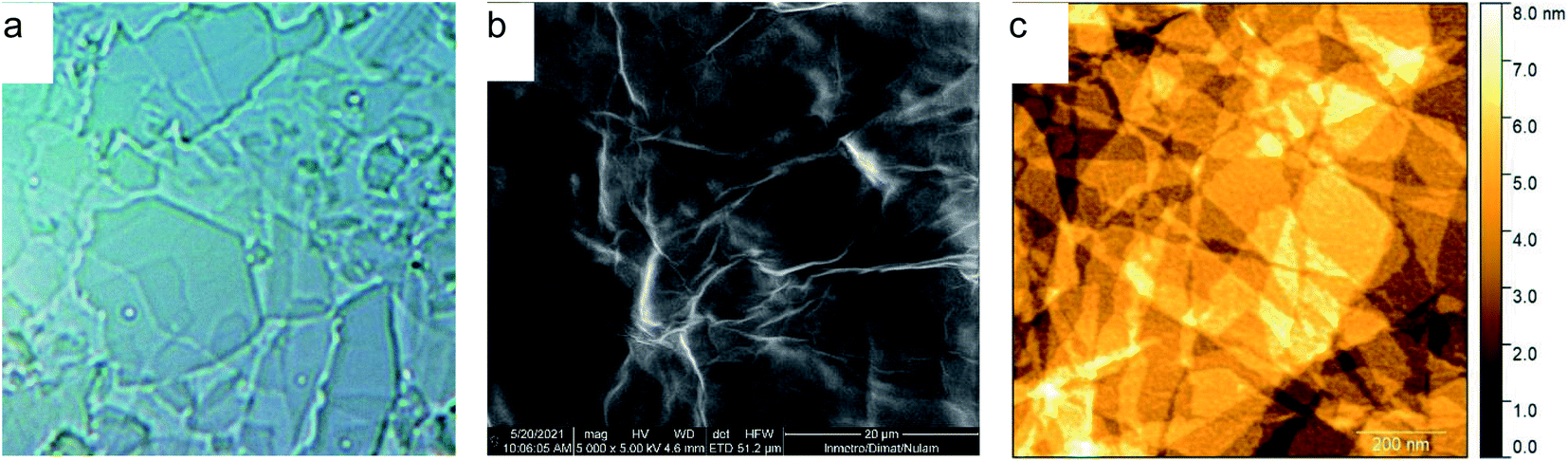 | ||
| Fig. 1 Images of GO samples in (a) optical (×400), (b) scanning electron, and (c) atomic force microscopies. | ||
3.2. N-GOQDs preparation
The purpose of this research was to develop the procedure of preparation and purification of N-GOQDs suitable for biomedical applications and thus to avoid the utilization of metal-containing oxidative agents due to difficulties related to their separation from the resulted nanoparticles. Therefore, water solution of H2O2 and ammonia has been used in the current as shredding agents for the preparation of N-GOQDs from GO under hydrothermal conditions. Shredding efficiency and thus yield of N-GOQDs depends both on the redox potential of the oxidant and the stability of GO. It was assumed that π–π stacking between graphitic layers in GO decreases the internal energy of multilayered GO. Thus shredding of multilayer GO requires utilization of strong metal-containing oxidative agents while few-layer GO can be etched even with H2O2.52 Indeed, by hydrothermal treatment of few-layer GO having only 2–5 nm of the flake thickness (Fig. 1c) N-GOQDs were obtained by hydrothermal treatment of H2O2 and ammonia with about 100% yield. The brown-yellow suspension obtained after such treatment did not contain visible amounts of precursor (GO) or other large particles that could be separated by micro-filtration or by high-speed centrifugation.UV-VIS spectrum of raw N-GOQDs in water demonstrates typical for GOQDs profile – gradually decrease strong absorption in UV-range with shoulders at 340 nm and 480 nm. In addition to the mentioned bands, the spectrum shows very broad absorption below 550 nm, Fig. 2 (inset). This absorption, which contributes to the brown color of the suspension, did not discuss in the literature, but can be attributed to contamination of N-GOQDs by other particles (for example, reduced GOQDs).
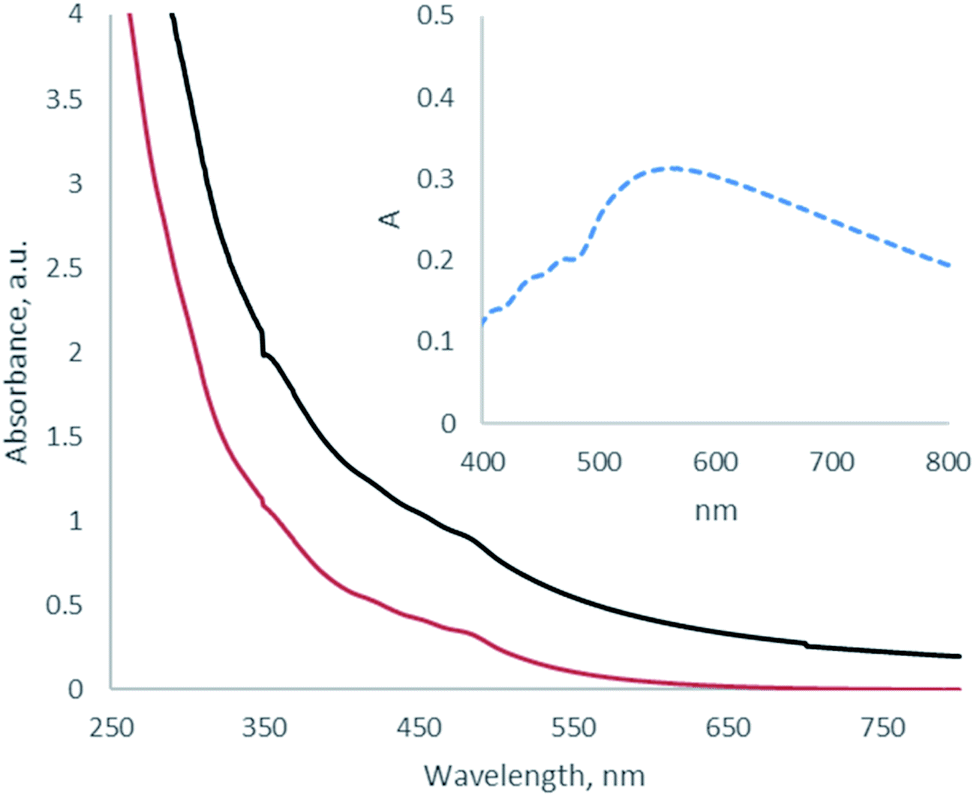 | ||
| Fig. 2 UV-VIS spectra of as-prepared N-GOQDs in water (black line) and 0.9 wt% NaCl solution (red line), and differential absorption spectrum (inset). | ||
It was demonstrated that N-GOQDs can be separated from such impurities by their coagulation in NaCl solution. The addition of solid NaCl to the suspension of raw N-GOQDs precipitates a small amount of black non-luminescent powder, that can be easily separated from yellow supernatant by centrifugation. Suspension of N-GOQDs demonstrates indefinite colloidal stability in physiological solution: no notable changes in UV-VIS spectra were detected during four months of the suspension storage at 4 °C. This enables the biomedical application of N-GOQDs.
3.3. The particles characterization
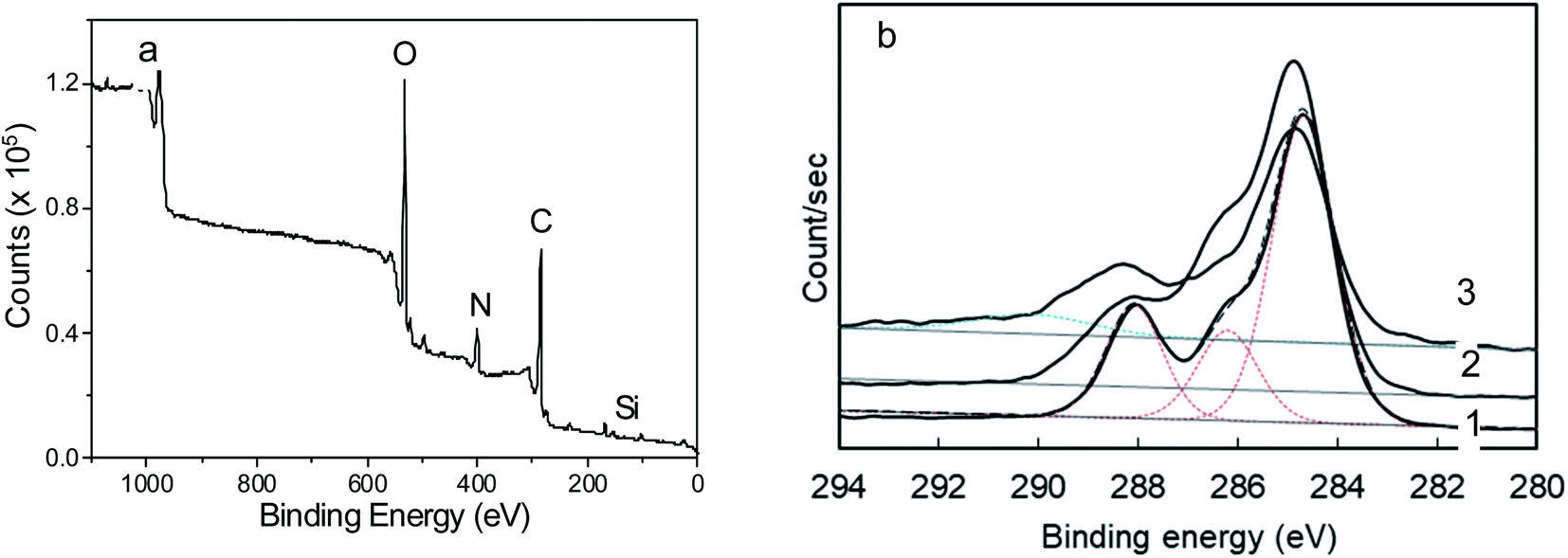 | ||
| Fig. 3 XPS spectra of N-GOQDs: (a) full-range XPS spectrum, (b) C 1s XPS spectrum of N-GOQDs obtained after two (1), four (2), and eight (3) hours of hydrothermal synthesis. Deconvoluted peaks are indicated by the dash lines. | ||
According to XPS data, the nanoparticles have a higher content of electronegative atoms (O and N) than parent GO. An increase in the synthesis time amplifies the content of hetero-atoms in N-GOQDs from 39.9% (for two-hour synthesis) to 49.1% (for eight-hour synthesis), Table 1. While the content of oxygen increases proportionally with the time of the synthesis, nitrogen doping has a superior limit of 7.2% reached within four hours of synthesis, Table 1.
| Sample | Atomic composition (at%) | ||
|---|---|---|---|
| C | O | N | |
| GO | 66.4 | 33.6 | <0.1 |
| N-GOQDs-2 | 60.1 | 34.6 | 5.3 |
| N-GOQDs-4 | 53.1 | 39.8 | 7.2 |
| N-GOQDs-8 | 50.9 | 45.3 | 3.8 |
To understand these phenomena, the high-resolution XPS of N-GOQDs has been studied. The C 1s spectra of N-GOQDs-2 show a peak with essential asymmetry, which allows its convolution to Gaussian peaks at 284.5, 286.2, and 288.1 eV, Fig. 3b. These results suggest that N-GOQDs obtained in two hours of synthesis mainly consist of graphene core with sp2 carbon atoms and C–N/C–O, and ![[double bond splayed left]](https://www.rsc.org/images/entities/char_e009.gif) C
C![[double bond, length as m-dash]](https://www.rsc.org/images/entities/char_e001.gif) O fragments.68 For N-GOQDs-4 peak intensity at 286.2 eV augments, indicating the formation of more defects C–N or C–O defects on graphene sp2 core. Together with this, widening of the peak at 284.5 eV can be observed, indicating the possible formation of C sp3 moieties. Also, the peak with a maximum at 288.1 eV receives a high energy tail, signifying the formation of some carboxylic (O–CO) moieties.68 XPS C 1s spectrum of the nanoparticles obtained in 8 h synthesis exhibits an essentially larger high-energy tail for the peak with a maximum at 288.1 eV and essentially less intensive peak at 286.2 eV, suggesting the further formation of O–CO fragments for N-GOQDs-8 nanoparticles with simultaneous decreasing of C–N or C–O moieties, Fig. 3b. The only XPS of GOQDs-8 shows a peak at 291 eV that can be attributed to shakeup satellites, indicating π → π* type transitions in graphene core.69
O fragments.68 For N-GOQDs-4 peak intensity at 286.2 eV augments, indicating the formation of more defects C–N or C–O defects on graphene sp2 core. Together with this, widening of the peak at 284.5 eV can be observed, indicating the possible formation of C sp3 moieties. Also, the peak with a maximum at 288.1 eV receives a high energy tail, signifying the formation of some carboxylic (O–CO) moieties.68 XPS C 1s spectrum of the nanoparticles obtained in 8 h synthesis exhibits an essentially larger high-energy tail for the peak with a maximum at 288.1 eV and essentially less intensive peak at 286.2 eV, suggesting the further formation of O–CO fragments for N-GOQDs-8 nanoparticles with simultaneous decreasing of C–N or C–O moieties, Fig. 3b. The only XPS of GOQDs-8 shows a peak at 291 eV that can be attributed to shakeup satellites, indicating π → π* type transitions in graphene core.69
The N 1s XPS spectra of N-GOQDs have different appearances depending on the time of the nanoparticle synthesis, Fig. 4. XPS for N-GOQDs-2 shows a symmetrical peak at 399.8 eV being attributed to (C)2–NH (denoted as N-5, Fig. 5) bonding, and a very weak peak at 406.7 eV. The spectrum of N-GOQDs-4 particles is deconvoluted into four peaks named N-5, N-6, N-Q, and N-X and their binding energy was constrained at 399.8, 400.6, 401.5, and 406.7 eV respectively.70 The N-6 peak is attributed to pyridinic nitrogen where a nitrogen atom substitutes for a carbon atom in an aromatic ring. The N-5 peak is related to organic nitrogen in pyrrolic derivatives and the nitrogen atom is just bonded to one hydrogen atom and two carbon atoms, amine, and amide. The N-Q peak is associated with quaternary nitrogen where the nitrogen atom substitutes the carbon atom in a condensed aromatic ring system and each nitrogen is bonded to three carbon atoms. The N-X peak is usually assigned to the pyridinic N-oxide (Fig. 4).70
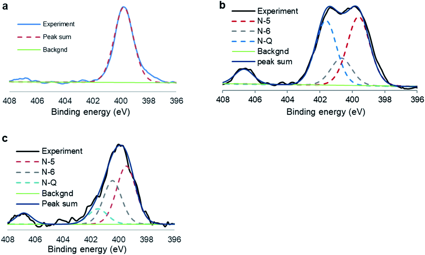 | ||
| Fig. 4 N 1s XPS spectra of N-GOQDs obtained after two (a), four (b), and eight (c) hours of hydrothermal synthesis. Deconvoluted peaks are indicated by the dash lines. | ||
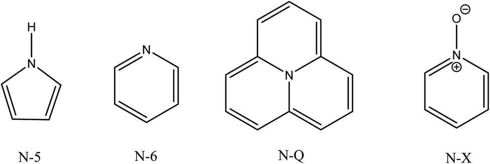 | ||
| Fig. 5 Schematic nitrogen-containing molecular structures. | ||
The functional composition of N-GOQDs estimated from the results of C 1s and N 1s XPS spectra is presented in Table 2.
| Sample | Nitrogen | |||
|---|---|---|---|---|
| N-5 | N-6 | N-Q | N-X | |
| N-GOQDs-2 | 100 | 0 | 0 | 0 |
| N-GOQDs-4 | 41.2 | 15.2 | 36.2 | 7.4 |
| N-GOQDs-8 | 47.2 | 33 | 12.3 | 7.5 |
From C 1s XPS data of N-GOQDs, it can be concluded that the nanoparticles obtained in two hours of synthesis consist of graphene core (62%) modified with C–N/C–O (18%) and CO (20%) moieties. With increasing the synthesis time graphene fraction is slightly reduced, while loading of lateral carboxylic groups rises to 9% of the total carbon content, Table 2. The XPS N 1s data demonstrate essential changes in the speciation of nitrogen for different N-GOQDs. The particles obtained in two hours of synthesis contain only N-5 moieties, while those prepared for a longer time have above 50% of other nitrogen-containing functional fragments, Table 2. Pyridine derivatives are much more stable to H2O2 treatment than N-5 and N-Q sites, therefore a fraction of N-6 moieties grows with the time of synthesis, while N-Q declines. Also, only N-6 fragments can react with H2O2 giving pyridine N-oxide derivatives. Thus, according to XPS quantitative analysis, N-GOQDs-8 can have up to 40.5% of the total nitrogen loading in form of pyridine derivatives, part of which (7.5%) can be in form of N-oxide (N-X sites), Table 2.
Taking to account the atomic content of N-GOQDs (Table 1) and the results of C 1s and N 1s XPS quantification (Table 2), the overall functional composition of the nanoparticles obtained in different experimental conditions has been determined. From the results presented in Fig. 6, it can be seen that increasing the time of N-GOQDs synthesis leads to gradual oxidation of the graphene layer and partial elimination of nitrogen moieties. In contrast, the fraction of lateral carboxylic groups increases with time.
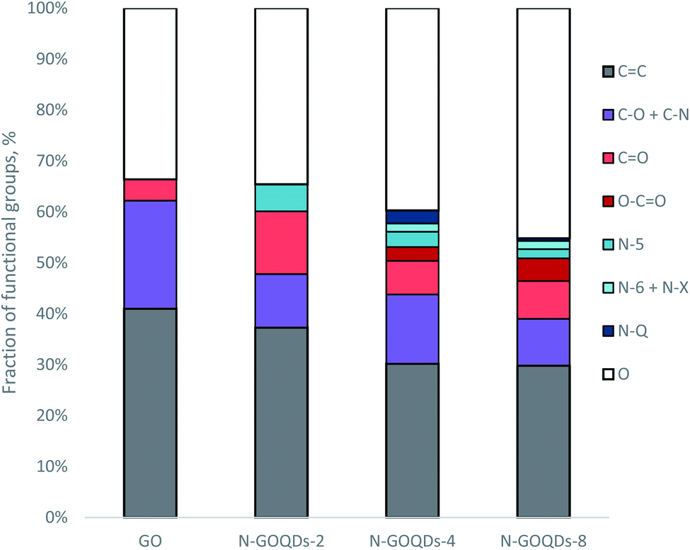 | ||
| Fig. 6 Relative functional composition of N-GOQDs obtained in two (N-GOQDs-2), four (N-GOQDs-2), and eight (N-GOQDs-2) hours of the hydrothermal synthesis. | ||
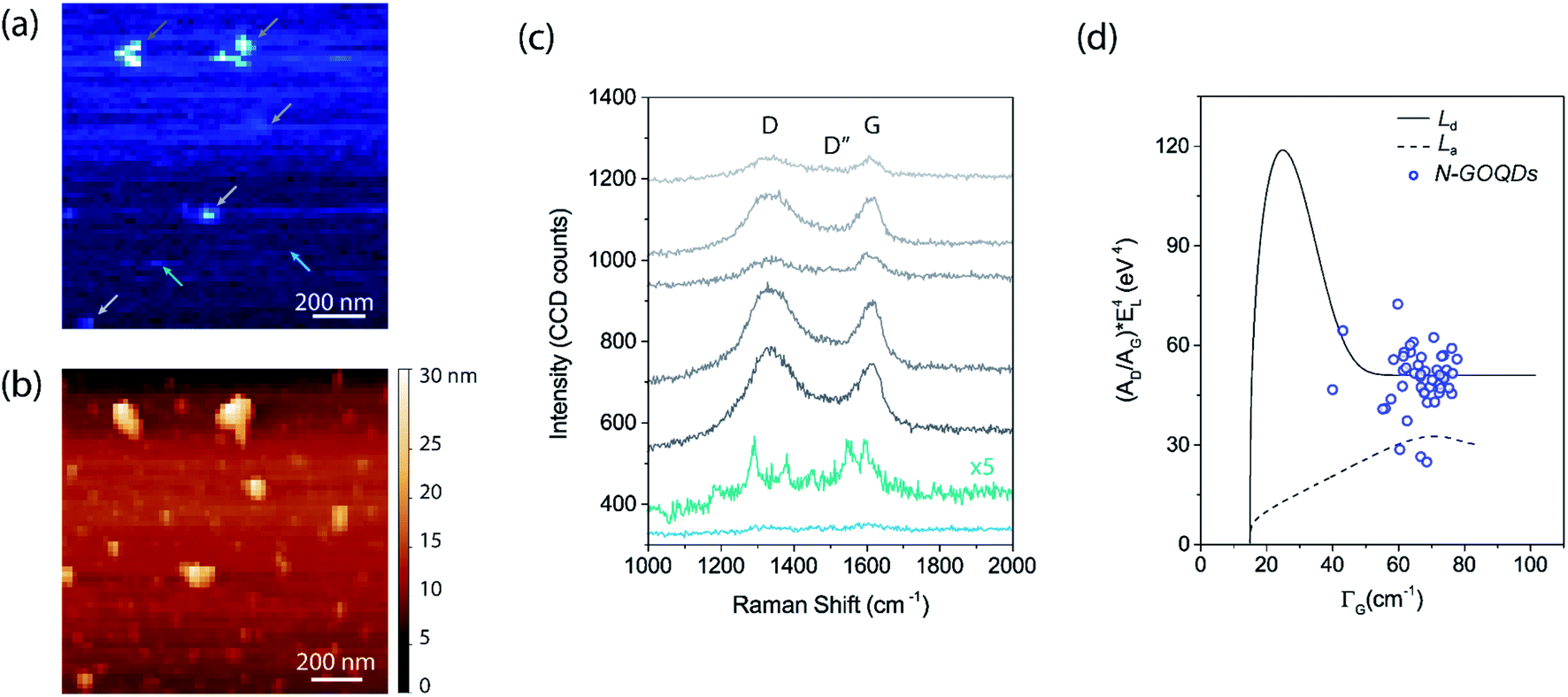 | ||
| Fig. 7 TERS analysis of N-GOQDs nanoparticles at glass coverslip substrate. (a) TERS hyperspectral image with a pixel size of 20 nm, blueish color rendering the G band. (b) Topography image simultaneously collected with the nano-Raman imaging, showing nanoparticles with a lateral size smaller than 50 nm well dispersed over the substrate and a few bigger nanoparticles agglomeration of around 100 nm. (c) TERS spectra were collected at pixel positions indicated by the arrows on image (a), where the grey color arrows with five distinct brightness are from the biggest nanoparticles, whereas the green and blue were collected elsewhere, indicating the optical information from the substrate (blue) and at a single N-GOQDs nanoparticle (green). All spectra were shifted, and the green spectrum was multiplied 5 times to clarity. (d) Scatter plot of the (AD/AG) × Elaser4 as function of the G band's linewidth (ΓG) from the data over the five biggest agglomerated nanoparticles. The black dashed and solid curves were adapted from the study of the influence of defects on the Raman spectra of graphene.74 The dashed curve was calculated for varying the average distance between nearest defects (LD) and considering a fixed value of the graphene average crystallite size LA = 500 nm. This solid curve was calculated for different values of LA, with LD fixed at 500 nm. | ||
Also, the intensity of the D and G bands and the width of the G band can be used to estimate the density of defects and the graphene crystallite size.72 To do so, we plotted in the graph (Fig. 9d) the data from the spectra acquired on the bigger nanoparticles. The graph shows the calculated (AD/AG) × Elaser4 as function of the G band linewidth ΓG, where Elaser is the energy of the laser used, which in our case is 1.96 eV, AD and AG are the area of the D and G peaks, calculated by fitting on the data three Lorentzian curves for the D (1336 cm−1), G (1605 cm−1) and D′ (1620 cm−1) peaks, and one Gaussian curve for the D′′ (1523 cm−1) peak. In the same graph, we included two curves adapted from the work of ref. 74. As better described in this referenced work, the dashed curve was calculated for varying the average distance between nearest defects (LD) and considering a fixed value of the graphene average crystallite size LA = 500 nm, whereas the black solid curve was calculated for different values of LA with fixed LD = 500 nm. By comparing our data, with mean values of (AD/AG) × Elaser4 = 50 eV4 and ΓG = 66 cm−1, to the data from ref. 74 we can assume that the N-GOQDs show graphene crystallite size of around 9 nm and LD smaller than 3 nm. These values found corroborates with the expected for a disorder carbon of N-GOQDs, even when considering the TERS effect on this methodology made for micro-Raman, which leads to a correction factor that would reduce the contribution of (AD/AG) × Elaser4, and thus improving the LD value for a few nanometers, as shown in the work of ref. 75.
Considering GO model proposed by Rourke76 and further developed by Hassenkam,77 the functional structure of N-GOQDs was proposed. The structure matches the results of the chemical analysis of the corresponding particles. Nitrogen dopants are mainly allocated in the graphene basal plane, while oxygen ones are on the particle edges, Fig. 8. It can be seen that different nitrogen sites of N-GOQDs generate different kinds of defects. Because the fractions of the sites depend on the particles' preparation conditions (Fig. 6), variation of such conditions can result in changing of optical and biomedical properties of the N-GOQDs. Also, the structure demonstrates heavy carboxylation of the particle edges, which explains experimentally observed high stability of the particle in water suspension and physiological solution. These observations can be useful to design N-GOQDs with specific functionality.
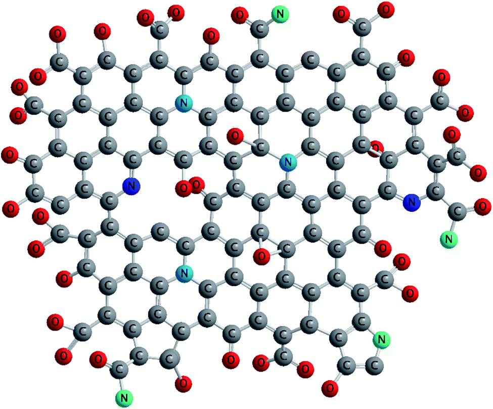 | ||
| Fig. 8 Schematical presentation of N-GOQDs-4. | ||
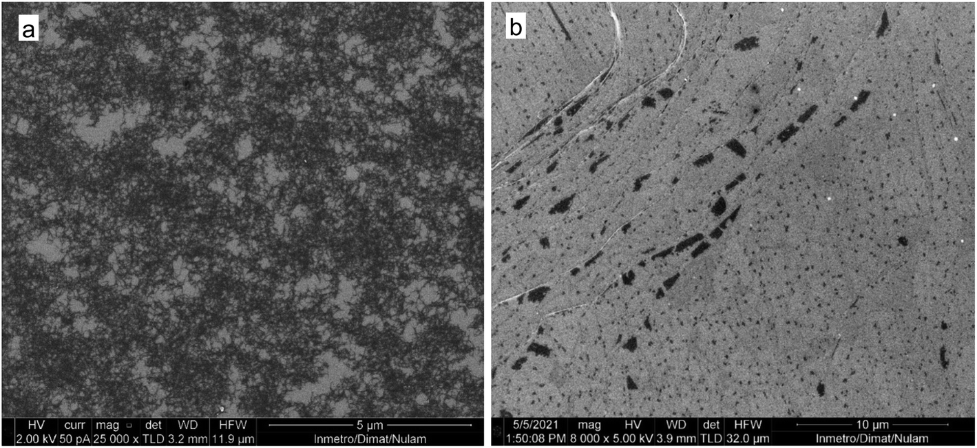 | ||
| Fig. 9 SEM images of the precipitate obtained by treatment of water suspension of raw N-GOQDs with 0.9 mL NaCl solution (a) and remaining supernatant (b). | ||
According to the result of TEM, N-GOQDs obtained in the current research have an irregular shape with an average lateral size of about 35 ± 10 nm, Fig. 10.
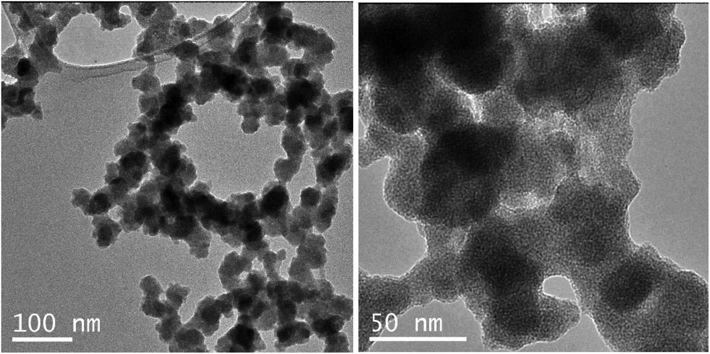 | ||
| Fig. 10 TEM image of N-GOQDs-8 obtained by hydrothermal treatment of GO with H2O2 and NH3. | ||
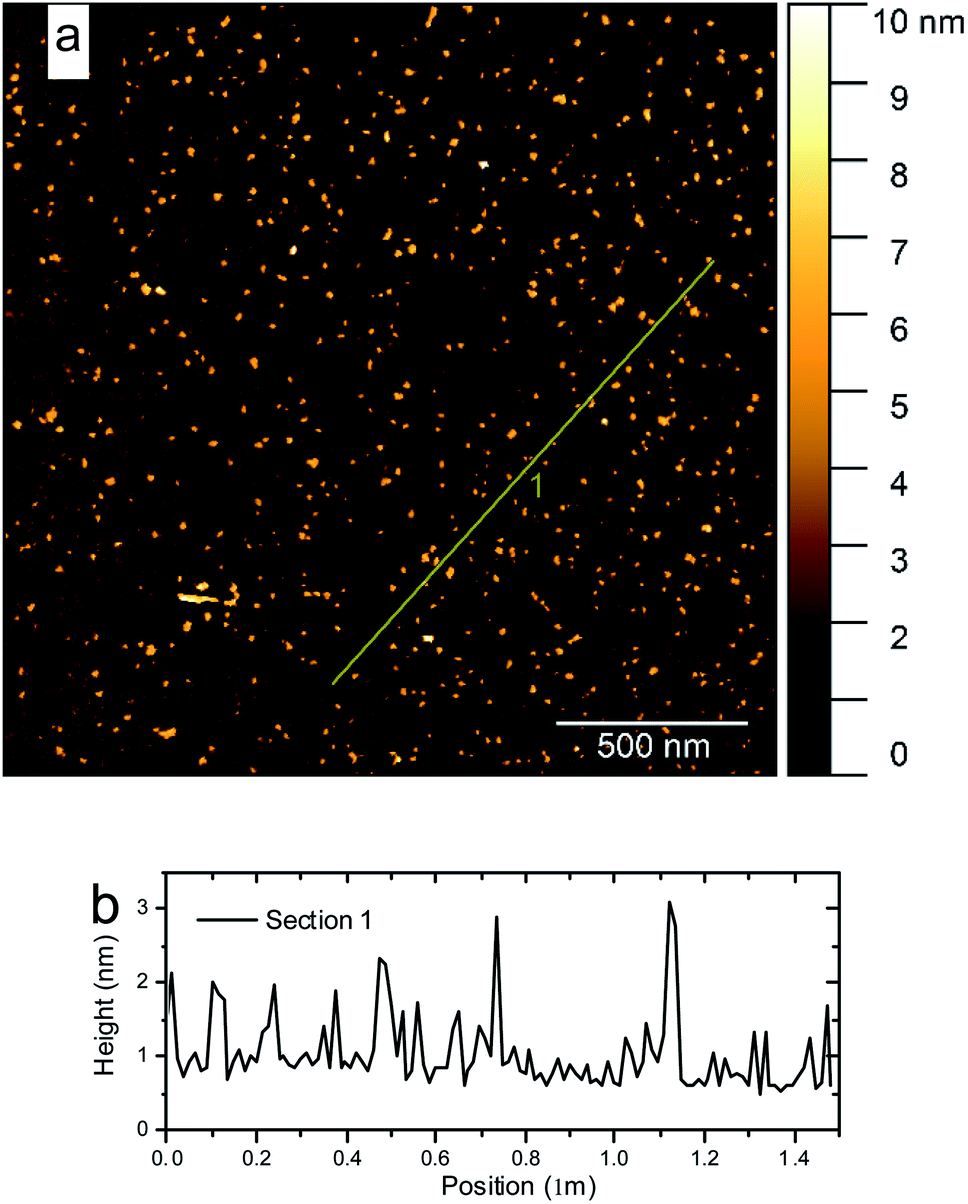 | ||
| Fig. 11 AFM images of the GOQDs (a) with their height profile along the line marked in the AFM image (b). | ||
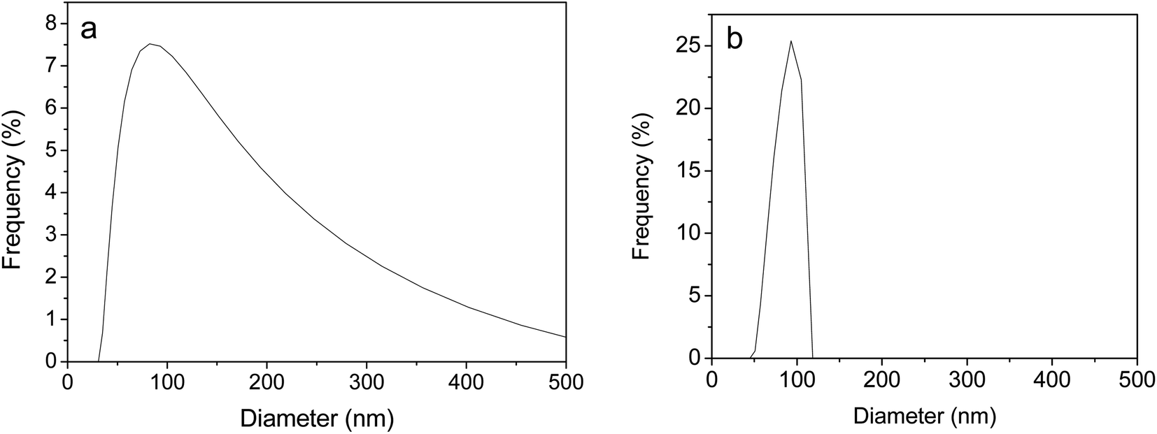 | ||
| Fig. 12 Dynamic light scattering of raw N-GOQDs-4 (a) and the same particles after purification with NaCl (b). | ||
3.4. Spectroscopic and photoluminescent properties of N-GOQDs
As-prepared N-GOQDs can be dried in a vacuum and then re-dispersed in water by vortex shaking or under ultrasound treatment. This action does not affect the UV-VIS spectra of N-GOQDs suspensions in water, reducing insignificantly (10–15%) the absorption intensity of the suspensions in a wide range of the nanoparticle concentration (from 2 × 10⁻¹ g L−1), Fig. 13.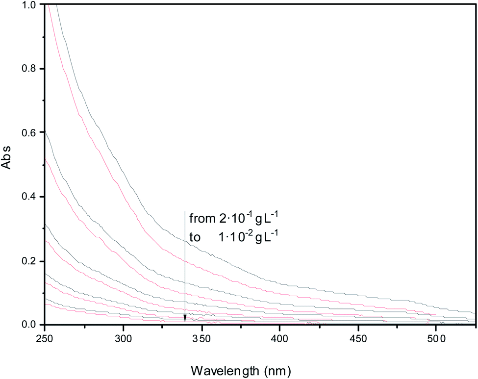 | ||
| Fig. 13 UV-VIS absorption spectra of water suspensions obtained at different concentrations of as-prepared (black lines) and re-dispersed (red lines) N-GOQDs. | ||
Due to essential variation in the particle size and chemical composition, samples of N-GOQDs demonstrate excitation-dependent photoluminescence, Fig. 14a. Photoemission at 460–520 nm can be successfully exited by visible light from 390 to 480 nm. When the N-GOQDs suspension is excited by light with a wavelength less than 430 nm, their photoemission band is wide and asymmetric. With the increase of the exited wavelength, the emission bandwidth decreases from its high-energy wing. At 430 nm of excitation, the emission band reaches its maximum intensity at 500 nm, Fig. 14b.
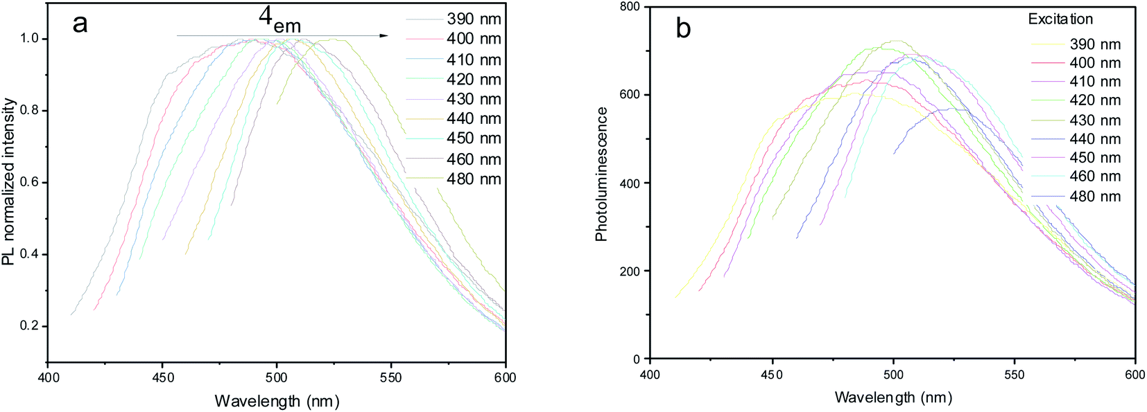 | ||
| Fig. 14 Normalized (a) and absolute (b) photoluminescence spectra of diluted N-GOQDs water suspension at different excitation wavelengths. | ||
Unlike UV-Vis spectroscopy, linear correlation between the concentration of N-GOQDs and photoluminescence emission is observed for diluted water suspension of the nanoparticles only, up to 100 mg L−1 (Fig. 15) due to the inner filter effect.
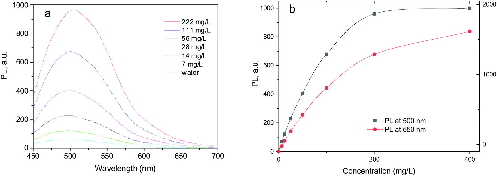 | ||
| Fig. 15 (a) Photoluminescence spectra of N-GOQDs suspensions in water (excitation wavelength 430 nm); (b) the variation of photoluminescence intensity as a function of N-GOQDs concentration. | ||
3.5. Cytotoxicity of N-GOQDs
First, it was shown that the suspension of N-GOQDs-4 in the M199 culture medium is stable. For this, the suspension luminescence was monitored periodically for 74 h, and no tendency of decrease was detected. Cytotoxicity results demonstrated that the viability of Vero cell line in the presence of N-GOQDs was not significantly lower than for positive control at all experimental conditions for 3, 6, 24, or 72 h of incubation. The significant difference in the comparison of the mean was revealed by negative control (NC) over the full kinetics profile. The saline as a reference was slightly different from the 1:100 dilution at 6 h of incubation (p = 0.0287, Fig. 16b) and to 1:10, 1:100 and PC at 24 h of incubation (p = 0.0074, 0.0127 and 0.0172, respectively Fig. 16c). In terms of decision-making, these values speak that p is not low enough to reject the null hypothesis for the equality of the means.
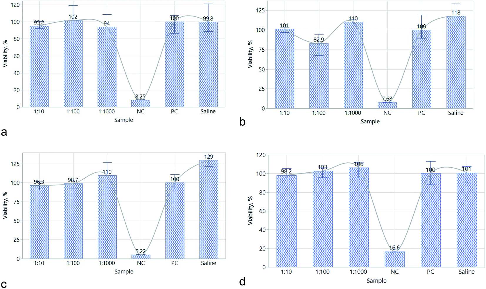 | ||
| Fig. 16 Viability of cells in sterilized and diluted (D) 10, 100, and 1000 times N-GOQDs sample in culture medium after 3 (a), 6 (b), 24 (c), and 72 (d) hours of treatment. | ||
Because of nomenclature perplexity, the data available on CDs cytotoxicity is very confused. Even in the latest reviews various CDs having different topology, composition and sizes are commonly considered as GQDs,78–80 which is wrong. It seems small spherical CNDs are less cytotoxic than plane large GQDs, probably due to different permeability and transport mechanisms.81,82 For example it was demonstrated that the viability of cancer cells (cervical cancer cells HeLa, lung carcinoma cells A549, etc.) decreases from 97% to 75% with increasing of CNDs particles size.83 For GOQDs having a lateral size above 50 nm, the viability of human glioma cells U251 is about 75% at the concentration of nanoparticles 0.1 mg mL−1 and incubation period of 24 hours.84 Other aspect of confusion is perplexity in doping (substation of carbon atoms of the graphene layer by heteroatoms) and functionalization (immobilization of various functional groups on the lateral sides of the particle) of CDs. It was demonstrated that nitrogen-functionalized CNDs are more cytotoxic than carboxylated or oxygenated ones, probably due to differences in surface charge.85 Contrary to CNDs, nitrogen-doped GQDs demonstrate even higher (over 90%) viability than pristine ones.83 This research shows that N-GOQDs can demonstrate even smaller cytotoxicity than N-GQDs with the viability of Vera cells up to 98% after 72 hours of incubation in 60 mg L−1 of N-GOQDs suspension, Fig. 16. Such effect can be explained by the functional structure of N-GOQDs (Fig. 8): the N-GOQDs are more oxygenated than N-GQDs, and they are heavily carboxylated on the edges. These two factors are in favor to reduce the cytotoxicity of N-GOQDs.82
4 Conclusions
It is demonstrated that N-GOQDs can be obtained from few-layer GO under hydrothermal treatment with H2O2 and ammonia with a yield of about 100%. The brown-yellow suspension obtained after such treatment did not contain visible amounts of precursor or other large particles that can be separated by micro-filtration or by high-speed centrifugation. Nevertheless, UV-Vis spectra of raw N-GOQDs show a very broad absorption band below 550 nm suggesting high molecular weight impurities that can be removed by coagulation with NaCl solution. Resulted re-dispersible N-GOQDs demonstrate indefinite stability of their suspensions in water and physiological solution. The chemical composition of N-GOQDs determined for XPS and TERS that the procedure proposed allows obtaining nitrogen-doped GOQDs with up to 7.2% of nitrogen. Deconvolution of C 1s peaks in high-resolution XPS allows to demonstrate that N-GOQDs obtained in two hours of synthesis mainly consist of graphene core with 18% of C–N or C–O defects, and about 20% of CO fragments located on the particle edges. The N-GOQDs obtained in 4–8 hours of hydrothermal treatment show heavy carboxylation of the particle edges. Analysis of high-resolution N 1s XPS allowed proving nitrogen doping of graphene core with formation of N-5, N-Q, N-6, and N-X defects. The fractional composition of nitrogen defects depends on the synthesis time. TEM, AFM, and TERS prove the planar topology of N-GOQDs with about 1.0–1.5 nm of height and 35 ± 10 nm of lateral size. The functional structure of N-GOQDs proposed demonstrates that nitrogen dopants are mainly allocated in the graphene basal plane, while oxygen ones are on the particle edges in form of carboxylic groups that ensure the particle solubility in water and physiological solutions. Due to essential variation in the particle size and chemical composition, samples of N-GOQDs demonstrate excitation-dependent photoluminescence with emission at 460–520 nm that can be excited by visible light. The N-GOQDs have exhibited outstanding compatibility with the monkey epithelial kidney cells (Vero), which are used in COVID-19 research, resulting in almost 100% viability. This fact proves the effectiveness of the applied techniques to prepare stable luminescent dispersions of GOQDs for further relevant uses.
Author contributions
Michael Nazarkovsky – investigation (NP synthesis and purification), formal analysis, writing; Albina Mikhraliieva – investigation (NP synthesis and spectroscopy), writing; Carlos A. Achete – supervision (microscopia, XPS, TERS); Luiz Anastacio Alves – methodology (bioactivity); Joyce Araujo – investigation (microscopia SEM); Bráulio S. Archanjo – investigation (microscopia TEM); Joé Júnior França de Barros – supervision (bioactivity); Liana Monteiro da Fonseca Cardoso – methodology (bioactivity); José Nelson S. S. Couceiro – investigation (bioactivity); Fernanda Davi Marques – investigation (XPS); Bruno S. Oliveira – investigation (TERS, RAMAN); Rafael Nascimento Dias de Souza – investigation (microscopia TEM); Ayla Josma Teixeira – investigation (bioactivity); Thiago L. Vasconcelos – investigation (TERS, RAMAN); Vladimir Zaitsev – conceptualization, supervision (NP synthesis), writing – original draft.Conflicts of interest
The authors declare no competing financial interest.Acknowledgements
Authors are grateful for the financial support received from Fundação Carlos Chagas Filho de Amparo à Pesquisa do Estado do Rio de Janeiro (FAPERJ) (grants E-26/010.155/2020, E-26/010.978/2019 and E-26/010.1556/2019). VZ gratefully acknowledges Conselho Nacional de Desenvolvimento Científico e Tecnológico (CNPq) (grants 306992/2018-3, 438450/2018-3) for financial support. TLV acknowledges financial support from Financiadora de Estudos e Projetos (FINEP) (grant SibratecNano 21040). This research used facilities of the Brazilian Nanotechnology National Laboratory (LNNano), part of the Brazilian Centre for Research in Energy and Materials (CNPEM), a private non-profit organization under the supervision of the Brazilian Ministry for Science, Technology, and Innovations (MCTI). The Spectroscopy and Scattering staff of LNNano is acknowledged for their assistance during the experiments (XPS-20220035). The AFM staff of LNNano is acknowledged for their assistance during the experiments (AFM-27716). The authors thank INMETRO and UFMG for the PTTPs nanoantennas used in the TERS experiment. We also acknowledge the help of Ricardo Queiroz Aucélio in obtaining and interpreting fluorescence spectra.References
- S. Anwar, H. Ding, M. Xu, X. Hu, Z. Li, J. Wang, L. Liu, L. Jiang, D. Wang, C. Dong, M. Yan, Q. Wang and H. Bi, ACS Appl. Bio Mater., 2019, 2, 2317–2338 CrossRef PubMed.
- X. Tian and X. Yin, Small, 2019, 15, 1901803 CrossRef CAS PubMed.
- C. Hu, M. Li, J. Qiu and Y.-P. Sun, Chem. Soc. Rev., 2019, 48, 2315–2337 RSC.
- X. Xu, R. Ray, Y. Gu, H. J. Ploehn, L. Gearheart, K. Raker and W. A. Scrivens, J. Am. Chem. Soc., 2004, 126, 12736–12737 CrossRef CAS PubMed.
- L. Wang, Y. Wang, T. Xu, H. Liao, C. Yao, Y. Liu, Z. Li, Z. Chen, D. Pan, L. Sun and M. Wu, Nat. Commun., 2014, 5, 5357 CrossRef CAS PubMed.
- Y. Park, J. Yoo, M.-H. Kang, W. Kwon and J. Joo, J. Mater. Chem. B, 2019, 7, 6271–6292 RSC.
- J. Shamsi, A. S. Urban, M. Imran, L. De Trizio and L. Manna, Chem. Rev., 2019, 119, 3296–3348 CrossRef CAS PubMed.
- H. Liu, J. Ding, K. Zhang and L. Ding, TrAC, Trends Anal. Chem., 2019, 118, 315–337 CrossRef CAS.
- R. Mohammadinejad, A. Dadashzadeh, S. Moghassemi, M. Ashrafizadeh, A. Dehshahri, A. Pardakhty, H. Sassan, S.-M. Sohrevardi and A. Mandegary, J. Adv. Res., 2019, 18, 81–93 CrossRef CAS PubMed.
- D. T. Omstead, J. Sjoerdsma and B. Bilgicer, Annu. Rev. Anal. Chem., 2019, 12, 69–88 CrossRef CAS PubMed.
- P. C. Wu, J. Y. Wang, W. L. Wang, C. Y. Chang, C. H. Huang, K. L. Yang, J. C. Chang, C. L. L. Hsu, S. Y. Chen, T. M. Chou and W. S. Kuo, Nanoscale, 2018, 10, 109–117 RSC.
- M. Pirsaheb, S. Mohammadi, A. Salimi and M. Payandeh, Microchim. Acta, 2019, 186, 231 CrossRef PubMed.
- M. K. Kumawat, M. Thakur, R. B. Gurung and R. Srivastava, Sci. Rep., 2017, 7, 1–16 CrossRef CAS PubMed.
- M. Pirsaheb, S. Mohammadi and A. Salimi, TrAC, Trends Anal. Chem., 2019, 115, 83–99 CrossRef CAS.
- Y. Yuan, B. Guo, L. Hao, N. Liu, Y. Lin, W. Guo, X. Li and B. Gu, Colloids Surf., B, 2017, 159, 349–359 CrossRef CAS PubMed.
- K. O. Boakye-Yiadom, S. Kesse, Y. Opoku-Damoah, M. S. Filli, M. Aquib, M. M. B. Joelle, M. A. Farooq, R. Mavlyanova, F. Raza, R. Bavi and B. Wang, Int. J. Pharm., 2019, 564, 308–317 CrossRef CAS PubMed.
- D. Lu, R. Tao and Z. Wang, Front. Chem. Sci. Eng., 2019, 13, 310–323 CrossRef CAS.
- Q. Wang, H. Zheng, Y. Long, L. Zhang, M. Gao and W. Bai, Carbon, 2011, 49, 3134–3140 CrossRef CAS.
- X. Zhang, S. Wang, C. Zhu, M. Liu, Y. Ji, L. Feng, L. Tao and Y. Wei, J. Colloid Interface Sci., 2013, 397, 39–44 CrossRef CAS PubMed.
- X. Li, H. Wang, Y. Shimizu, A. Pyatenko, K. Kawaguchi and N. Koshizaki, Chem. Commun., 2011, 47, 932–934 RSC.
- F. Yuan, L. Ding, Y. Li, X. Li, L. Fan, S. Zhou, D. Fang and S. Yang, Nanoscale, 2015, 7, 11727–11733 RSC.
- S. Zhu, X. Zhao, Y. Song, S. Lu and B. Yang, Nano Today, 2016, 11, 128–132 CrossRef CAS.
- D. Qu and Z. Sun, Mater. Chem. Front., 2020, 4, 400–420 RSC.
- S. Shen, J. Wang, Z. Wu, Z. Du, Z. Tang and J. Yang, Nanomaterials, 2020, 10, 375 CrossRef CAS PubMed.
- S. Mandal and P. Das, Appl. Mater. Today, 2022, 26, 101331 CrossRef.
- A. Mikhraliieva, V. Zaitsev, Y. Xing, H. Coelho-Júnior and R. L. Sommer, ACS Appl. Nano Mater., 2020, 3, 3652–3664 CrossRef CAS.
- Z. Song, X. Wang, G. Zhu, Q. Nian, H. Zhou, D. Yang, C. Qin and R. Tang, Small, 2015, 11, 1171–1176 CrossRef CAS PubMed.
- K.-W. Chu, S. Lee, C.-J. Chang and L. Liu, Polymers, 2019, 11, 689 CrossRef CAS PubMed.
- H. Li, Z. Kang, Y. Liu and S. T. Lee, J. Mater. Chem., 2012, 22, 24230–24253 RSC.
- A. J. G. Afonso, F. T. Aquino, G. M. L. Dalmônico, M. V. Nascimento, E. Wrasse and K. M. F. R. de Aguiar, Carbon Lett., 2022, 32, 131–141 CrossRef.
- A. Ghosh and G. Das, New J. Chem., 2021, 45, 8747–8754 RSC.
- S. Perumal, R. Atchudan, T. N. J. I. Edison and Y. R. Lee, J. Environ. Chem. Eng., 2021, 9, 105802 CrossRef CAS.
- A. Cayuela, M. L. Soriano, C. Carrillo-Carrión and M. Valcárcel, Chem. Commun., 2016, 52, 1311–1326 RSC.
- J. B. Essner, J. A. Kist, L. Polo-Parada and G. A. Baker, Chem. Mater., 2018, 30, 1878–1887 CrossRef CAS.
- P. Tian, L. Tang, K. S. Teng and S. P. Lau, Mater. Today Chem., 2018, 10, 221–258 CrossRef CAS.
- Y. Yan, J. Gong, J. Chen, Z. Zeng, W. Huang, K. Pu, J. Liu and P. Chen, Adv. Mater., 2019, 31, 1–22 Search PubMed.
- F. Rigodanza, M. Burian, F. Arcudi, L. Đorđević, H. Amenitsch and M. Prato, Nat. Commun., 2021, 12, 2640 CrossRef CAS PubMed.
- L. Zhao, L. Zhao, H. Li, J. Ma, L. Bian, X. Wang and Q. Pu, Talanta, 2021, 228, 122224 CrossRef CAS PubMed.
- S. Mani, G. Swargiary, S. Tyagi, M. Singh, N. K. Jha and K. K. Singh, Life Sci., 2021, 281, 119773 CrossRef CAS PubMed.
- X. Dong, R. Edmondson, F. Yang, Y. Tang, P. Wang, Y.-P. Sun and L. Yang, RSC Adv., 2020, 10, 33944–33954 RSC.
- Y.-Y. Chen, W.-P. Jiang, H.-L. Chen, H.-C. Huang, G.-J. Huang, H.-M. Chiang, C.-C. Chang, C.-L. Huang and T.-Y. Juang, RSC Adv., 2021, 11, 16661–16674 RSC.
- T. S. Hauck, R. E. Anderson, H. C. Fischer, S. Newbigging and W. C. W. Chan, Small, 2010, 6, 138–144 CrossRef CAS PubMed.
- Y. Liu, H. Huang, W. Cao, B. Mao, Y. Liu and Z. Kang, Mater. Chem. Front., 2020, 4, 1586–1613 RSC.
- A. Kasouni, T. Chatzimitakos and C. Stalikas, in Comprehensive Analytical Chemistry, 2021, vol. 94, pp. 507–531 Search PubMed.
- A. Rhazouani, H. Gamrani, M. El Achaby, K. Aziz, L. Gebrati, M. S. Uddin and F. Aziz, BioMed Res. Int., 2021, 2021, 1–19 CrossRef PubMed.
- N. Kottam and S. P. Smrithi, Methods Appl. Fluoresc., 2021, 9, 012001 CrossRef CAS PubMed.
- S. Tajik, Z. Dourandish, K. Zhang, H. Beitollahi, Q. Van Le, H. W. Jang and M. Shokouhimehr, RSC Adv., 2020, 10, 15406–15429 RSC.
- X. Hu, X. An and L. Li, Mater. Sci. Eng., C, 2016, 58, 730–736 CrossRef CAS PubMed.
- X. Xu, D. Ren, Y. Chai, X. Cheng, J. Mei, J. Bao, F. Wei, G. Xu, Q. Hu and Y. Cen, Sens. Actuators, B, 2019, 298, 126829 CrossRef CAS.
- O. E. Trubetskaya, O. A. Trubetskoj, C. Richard, A. M. Vervald, S. A. Burikov, V. V. Marchenkov, O. A. Shenderova, S. V. Patsaeva and T. A. Dolenko, J. Chromatogr. A, 2021, 1650, 462251 CrossRef CAS PubMed.
- X. Zhou, Y. Zhang, C. Wang, X. Wu, Y. Yang, B. Zheng, H. Wu, S. Guo and J. Zhang, ACS Nano, 2012, 6, 6592–6599 CrossRef CAS PubMed.
- M. R. Younis, G. He, J. Lin and P. Huang, Front. Chem., 2020, 8, 424 CrossRef CAS PubMed.
- R. Tian, S. Zhong, J. Wu, W. Jiang, Y. Shen, W. Jiang and T. Wang, Opt. Mater., 2016, 60, 204–208 CrossRef CAS.
- Q. Liu, J. Zhang, H. He, G. Huang, B. Xing, J. Jia and C. Zhang, Nanomaterials, 2018, 8, 844 CrossRef PubMed.
- X. Tong, M. Cherif, G. Zhang, X. Zhan, J. Ma, A. Almesrati, F. Vidal, Y. Song, J. P. Claverie and S. Sun, ACS Appl. Mater. Interfaces, 2021, 13, 30512–30523 CrossRef CAS PubMed.
- M. Havrdova, K. Hola, J. Skopalik, K. Tomankova, M. Petr, K. Cepe, K. Polakova, J. Tucek, A. B. Bourlinos and R. Zboril, Carbon, 2016, 99, 238–248 CrossRef CAS.
- K.-A. Tsai, P.-Y. Hsieh, T.-H. Lai, C.-W. Tsao, H. Pan, Y.-G. Lin and Y.-J. Hsu, ACS Appl. Energy Mater., 2020, 3, 5322–5332 CrossRef CAS.
- C. T. Cao, S.-W. Kim, H. J. Kim, R. Purbia, S. H. Kim, D. Kim, K. J. Choi, H. Park and J. M. Baik, Nano Energy, 2022, 96, 107117 CrossRef CAS.
- A. Sheini, A. Taherpour, M. Maghsudi, S. Farajmand-Amirabadi, M. Kouchak, N. Rahbar, M. Sabaeian and H. Alidadi, Colloids Surf., A, 2022, 636, 128066 CrossRef CAS.
- M. Kaur, M. Kaur and V. K. Sharma, Adv. Colloid Interface Sci., 2018, 259, 44–64 CrossRef CAS PubMed.
- T. Mosmann, J. Immunol. Methods, 1983, 65, 55–63 CrossRef CAS PubMed.
- L. G. Cançado, A. Hartschuh and L. Novotny, J. Raman Spectrosc., 2009, 40, 1420–1426 CrossRef.
- C. Rabelo, H. Miranda, T. L. Vasconcelos, L. G. Cancado and A. Jorio, in 2019 4th International Symposium on Instrumentation Systems, Circuits and Transducers (INSCIT), IEEE, 2019, pp. 1–6 Search PubMed.
- T. L. Vasconcelos, B. S. Archanjo, B. S. Oliveira, R. Valaski, R. C. Cordeiro, H. G. Medeiros, C. Rabelo, A. Ribeiro, P. Ercius, C. A. Achete, A. Jorio and L. G. Cançado, Adv. Opt. Mater., 2018, 6, 1800528 CrossRef.
- B. S. Oliveira, B. S. Archanjo, R. Valaski, C. A. Achete, L. G. Cançado, A. Jorio and T. L. Vasconcelos, J. Chem. Phys., 2020, 153, 114201 CrossRef CAS PubMed.
- H. Miranda, C. Rabelo, T. L. Vasconcelos, L. G. Cançado and A. Jorio, Phys. Status Solidi RRL, 2020, 14, 2000212 CrossRef CAS.
- A. Mikhraliieva, V. Zaitsev, O. Tkachenko, M. Nazarkovsky, Y. Xing and E. V. Benvenutti, RSC Adv., 2020, 10, 31305–31315 RSC.
- C. Hu, T. R. Su, T. J. Lin, C. W. Chang and K. L. Tung, New J. Chem., 2018, 42, 3999–4007 RSC.
- H. Tilborg, A. Nilsson and N. Mårtensson, J. Electron Spectrosc. Relat. Phenom., 1993, 62, 73–93 CrossRef.
- X. Liu, F. Zhao, H. Guo, D. Xia, Z. Dong and Z. Li, Environ. Sci. Pollut. Res., 2022, 29, 33495–33505 CrossRef CAS PubMed.
- T. L. Vasconcelos, B. S. Archanjo, B. S. Oliveira, W. F. Silva, R. S. Alencar, C. Rabelo, C. A. Achete, A. Jorio and L. G. Cancado, IEEE J. Sel. Top. Quantum Electron., 2021, 27, 1–11 Search PubMed.
- S. Claramunt, A. Varea, D. López-Díaz, M. M. Velázquez, A. Cornet and A. Cirera, J. Phys. Chem. C, 2015, 119, 10123–10129 CrossRef CAS.
- A. Maghsoumi, L. Brambilla, C. Castiglioni, K. Müllen and M. Tommasini, J. Raman Spectrosc., 2015, 46, 757–764 CrossRef CAS.
- L. Gustavo Cançado, M. Gomes da Silva, E. H. Martins Ferreira, F. Hof, K. Kampioti, K. Huang, A. Pénicaud, C. Alberto Achete, R. B. Capaz and A. Jorio, 2D Mater., 2017, 4, 025039 CrossRef.
- C. Rabelo, T. L. Vasconcelos, B. C. Publio, H. Miranda, L. G. Cançado and A. Jorio, Phys. Rev. Appl., 2020, 14, 024056 CrossRef CAS.
- J. P. Rourke, P. A. Pandey, J. J. Moore, M. Bates, I. A. Kinloch, R. J. Young and N. R. Wilson, Angew. Chem., Int. Ed., 2011, 50, 3173–3177 CrossRef CAS PubMed.
- Z. Liu, K. Nørgaard, M. H. Overgaard, M. Ceccato, D. M. A. Mackenzie, N. Stenger, S. L. S. Stipp and T. Hassenkam, Carbon, 2018, 127, 141–148 CrossRef CAS.
- I. S. Raja, A. Molkenova, M. S. Kang, S. H. Lee, J. E. Lee, B. Kim, D.-W. Han and T. S. Atabaev, in Advances in experimental medicine and biology, 2022, vol. 1351, pp. 23–39 Search PubMed.
- L. Liang, X. Peng, F. Sun, Z. Kong and J. W. Shen, Nanoscale Adv., 2021, 3, 904–917 RSC.
- X. Zhao, W. Gao, H. Zhang, X. Qiu and Y. Luo, in Handbook of Nanomaterials in Analytical Chemistry, Elsevier, 2020, pp. 493–505 Search PubMed.
- X. Wang, R. Lei, H. Huang, N. Wang, L. Yuan, R. Xiao, L. Bai, X. Li, L. Li and X. Yang, Nanoscale, 2015, 7, 2034–2041 RSC.
- S. Achawi, J. Pourchez, B. Feneon and V. Forest, Chem. Res. Toxicol., 2021, 34, 2003–2018 Search PubMed.
- S. Wang, I. S. Cole and Q. Li, RSC Adv., 2016, 6, 89867–89878 RSC.
- Z. M. Markovic, B. Z. Ristic, K. M. Arsikin, D. G. Klisic, L. M. Harhaji-Trajkovic, B. M. Todorovic-Markovic, D. P. Kepic, T. K. Kravic-Stevovic, S. P. Jovanovic, M. M. Milenkovic, D. D. Milivojevic, V. Z. Bumbasirevic, M. D. Dramicanin and V. S. Trajkovic, Biomaterials, 2012, 33, 7084–7092 CrossRef CAS PubMed.
- Z. Tu, K. Achazi, A. Schulz, R. Mülhaupt, S. Thierbach, E. Rühl, M. Adeli and R. Haag, Adv. Funct. Mater., 2017, 27, 1701837 CrossRef.
| This journal is © The Royal Society of Chemistry 2022 |