 Open Access Article
Effect of MWCNT nanofiller on the dielectric performance of bio-inspired gelatin based nanocomposites†
Rabeya Binta Alam,
Md. Hasive Ahmad and
Muhammad Rakibul Islam *
*
Department of Physics, Bangladesh University of Engineering and Technology (BUET), Dhaka, Bangladesh. E-mail: rakibul@phy.buet.ac.bd
First published on 16th May 2022
Abstract
In this work, multi wall carbon nanotube (MWCNT) reinforced bio-derived gelatin-based polymer nanocomposites were synthesized following an easy and affordable solution-casting method. The effects of different concentrations of MWCNTs on the structural, surface morphological, and dielectric properties of the nanocomposites were studied. A four-fold increase in the dielectric constant is observed due to the incorporation of just 0.02 wt% of MWCNT nanofiller into the polymer matrix. The modified Cole–Cole model was used to analyze the effect of nanofiller concentrations on the different dielectric parameters of the nanocomposite. The incorporation of MWCNTs was found to increase the dielectric strength and reduce the relaxation time of the nanocomposite. The AC conductivity of the nanocomposites was found to be improved due to the incorporation of the MWCNT nanofiller. A quantitative study based on the simulation of the complex impedance spectra demonstrates that the addition of MWCNTs into the nanocomposite decreases the grain barrier resistance from 5935 kΩ to 261 kΩ and increases the capacitive component from 0 to 23.25 μF. The improved dielectric performance of the nanocomposites can be attributed to the space charge polarization effect and is illustrated with a charge transport mechanism model. This biopolymer-based nanocomposite material with a large dielectric constant together with a small loss tangent may offer a potential route for the fabrication of fully biocompatible electrostatic capacitors and energy storage devices.
1. Introduction
Nanoparticle reinforced polymer composites with preferred characteristics are gaining significant attention among researchers for their potential application in a wide range of industrial sectors such as packaging, artificial biomedical implants, electrical devices, electronics, etc.1–4 Among them, functional polymer materials with high dielectric constant, low dielectric loss and flexibility are highly desirable in producing next-generation smart devices, such as decoupling capacitors, electric vehicles, solar photovoltaic generation plants, sensors and actuators, electromagnetic interference (EMI) shielding, switched-mode power supplies, etc.5–7 As a result, in fabricating efficient electrostatic capacitors for advanced electronic and electrical-power applications, polymer-based nanocomposites are replacing the conventional ceramic-based dielectric materials due to their easy processing, low cost, excellent flexibility, and high energy density together with superior mechanical properties.8–10 So far most of the polymers used in different device applications originated from the synthetic route and are non-bio-friendly as a result use of these polymers is a major concern for the nature and environment.11 The best possible alternative to this is to use bio-derived polymers instead of synthetic polymers. Bio-polymers are abundant in nature, cost-effective, easy to process, and obviously bio-compatible.12,13 A variety of biopolymers including starch, cellulose, PLA, gelatin, etc. have been used as the matrix for the polymer nanocomposite.14–16 In particular, gelatin, a natural biopolymer obtained from the hydrolysis of fibrous insoluble collagen present in bones and skin is regarded as one of the most promising candidates for biodegradable and transient electronic applications because of its renewable nature, availability, low price, easy processability and degradability.17,18 Among varieties of nanofillers, carbon nanotube (CNT), rolled up cylindrical sheet of graphene, are considered as one of the most popular nanofiller for polymer matrix.19 The excellent conductivity and extraordinary surface-to-volume ratio of the CNT offer synthesis of robust polymer nanocomposite together with improved dielectric performance.20,21 So far, several attempts have been made to synthesize polymer-based dielectric material with large dielectric constant and smaller dielectric loss tangents by introducing CNT nanofillers into the polymer matrix. For instance, Fan et al. reported a sandwich-structured composite polydimethylsiloxane/carbon nanotube (PDMS/CNT) film synthesizes by the spin-coating method.22 The composites showed a dielectric permittivity of 40 and a loss tangent of 0.01 at 100 Hz. Liao et al. worked with polyimide, MWCNT, and graphene oxide (GO).23 The composites with a homogeneous distribution of CNT and GO/PI show dielectric permittivity and dielectric loss of 124.9 and 1.97 at 100 Hz, respectively. Xiao et al. reported a greater relative permittivity of 5200 together with a tangent loss of 1.2 for CNT-based nanocomposite of polyvinylidene fluoride (PVDF)/boron nitride (BN).24 In another work, polyethylene–MWCNT with cyanate ester nanocomposite was synthesized by Wang et al. where a smaller dielectric loss tangent of 0.008 was obtained but the dielectric constant was only 168.25In spite of the above-mentioned properties, the use of multi-walled carbon nanotube (MWCNT) based polymer nanocomposites as electrode materials in an electrostatic capacitor has garnered little attention, and the dielectric performance of this type of material has received only little consideration. The objective of this research is to investigate and improve the dielectric characteristics of biodegradable gelatin polymer by introducing MWCNT nanofiller into the polymer matrix. Several research groups have recently published articles on the synthesis and characterization of gel/MWCNT nanocomposite.26–28 In their works mostly the structure, surface morphology, and the thermal and mechanical performance of the gel/MWCNT nanocomposite were primarily investigated. However, to the best of our knowledge, no study on detailed analysis of the dielectric performance of the gel/MWCNT nanocomposites has yet been published. No reported study has yet provided quantitative analysis or simulation using any model or circuit fitting of the dielectric parameters of biodegradable nanocomposite material. This study provides a detailed analysis of the complex dielectric constant and complex dielectric impedance with appropriate modeling and simulation methods for bio-originated polymer and their nanocomposites. Gel/MWCNT nanocomposites were created using the solution casting approach in this study, a prominent solution-processed technology for the production of polymer nanocomposites. The solution casting technique possesses a number of advantages including low-temperature processing, simple, low-cost, and straightforward preparation of materials.29 The gel/MWCNT composites displayed both stable high dielectric permittivity and a low loss tangent at normal atmospheric conditions. With an appropriate mechanism, the relaxation behavior and conduction mechanism of nanocomposites were also studied. The complete study of this biomaterial with excellent dielectric properties may find its use in flexible biofriendly next-generation electronic devices.
2. Materials and methods
2.1 Materials
Sigma-Aldrich delivered gelatin powder (type B from bovine skin, 200 Bloom) and glycerol (98% pure). Tokyo Chemical Industry Co., Ltd. supplied the multi-wall carbon nanotube. The MWCNT has an average diameter of 30 nm and a length of 10 m, respectively. All the materials were used as bought without any further modification.2.2 Preparation of gel/MWCNT nanocomposite film
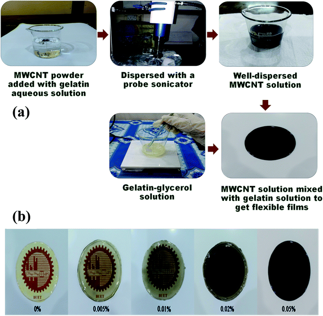
All the aqueous solutions were prepared with DI water. An appropriate amount of gelatin was mixed with DI water and was heated up to 50 °C with continuous magnetic stirring until they dissolved properly. For the synthesis of nano-composite high-quality MWCNTs were dispersed in DI water with a minute amount of gelatin solution using a probe sonicator until a homogenously dispersed solution was attained. MWCNT of different proportions (0 wt%, 0.005 wt%, 0.01 wt%, 0.02 wt%, and 0.05 wt%) were mixed with the previously obtained gelatin solution. Then glycerol was added to this solution as a plasticizer and was stirred at 70 °C for about 40 min until the solution was thickened. The solution was then poured onto a glass Petri dish and kept at room temperature for several hours. The films were gently peeled out of the Petri dish later, and they were ready to be studied for various properties (Fig. 1).2.3 Characterization techniques
Fourier transform infrared spectroscopy (FTIR) analysis was used to investigate the presence of various groups in the cross-linked nanocomposites. The chemical analysis was performed using a (Shimadzu IRSpirit) spectrophotometer in the spectral range of 500–4000 cm−1.A field emission scanning electron microscope (FESEM) model no. JEOL JSM-7600F was used to examine the surface morphology of the gel/MWCNT nanocomposite. The composites were coated with a thin gold/palladium coating before imaging.
A portable network analyzer was used to test the dielectric characteristics of the samples (FieldFox N9923A, Agilent Technologies Inc.). The measurement was conducted following the ‘Parallel Plate Capacitor’ method. The parallel plate capacitor method involves sandwiching a thin sheet of material between two electrodes of the vector network analyzer (VNA) to form a capacitor. The prepared self-substrate film material is connected to the analyzer by touching the parallel plates to the upper and the lower flat surfaces of the sample in such a way that no air gap is formed between the two contact surfaces. The characterization was carried out at room temperature from 40 Hz to 10 MHz frequency range. The capacitance (C) of the film was used to determine dielectric permittivity,  where d = thinness of the film, A = working area of the film, ε0 = permittivity of vacuum. Dielectric loss tangent, tan
![[thin space (1/6-em)]](https://www.rsc.org/images/entities/char_2009.gif) δ was obtained directly from the analyzer. The formula used to determine the imaginary part of the permittivity is, ε′′ = ε′
δ was obtained directly from the analyzer. The formula used to determine the imaginary part of the permittivity is, ε′′ = ε′![[thin space (1/6-em)]](https://www.rsc.org/images/entities/char_2009.gif) tan
tan![[thin space (1/6-em)]](https://www.rsc.org/images/entities/char_2009.gif) δ. The formula has been used to determine AC conductivity is, σAC = ωε0ε′
δ. The formula has been used to determine AC conductivity is, σAC = ωε0ε′![[thin space (1/6-em)]](https://www.rsc.org/images/entities/char_2009.gif) tan
tan![[thin space (1/6-em)]](https://www.rsc.org/images/entities/char_2009.gif) δ.15,30
δ.15,30
3. Results and discussions
3.1 Structural properties
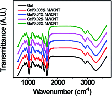
Chemical compositions and molecular interaction of the prepared gel/MWCNT nanocomposites were studied using Fourier Transform Infrared (FTIR) spectroscopy technique and are shown in Fig. 2. Here observed main functional groups of gelatin were located at 1036, 1110, 1549, 1636, 2883, and 2935 cm−1.31 Also, a large absorption peak ranging from 3100 cm−1 to 3500 cm−1 was observed due to the –OH stretching vibration originating from the functional hydroxyl groups presented in gelatin, glycerol, and bound water from the solution.1 The two significant peaks at 2883 cm−1 and 2935 cm−1 are similar to the peptide bonds of amide-A and amide-B respectively. Amide-A originates from NH-stretching and hydrogen bonding, whereas amide-B corresponds to NH4+ and CH-bonding.32 The peak for amide I corresponding to the C![[double bond, length as m-dash]](https://www.rsc.org/images/entities/char_e001.gif) O stretching and NH bending vibrations is found at 1636 cm−1. The peak for amide II which rises from CN stretching and CO bending vibrations is found at 1549 cm−1. An additional amide I peak corresponding to the CH2 fluctuation is observed at 1110 cm−1.33 The observed increment of the peak's intensity with the MWCNT concentrations indicates enhanced interaction between the polymer and the nanofiller. The active hydroxyl bonds of the gelatin chain might have created possible interactive sights for the MWCNTs to attach.34
O stretching and NH bending vibrations is found at 1636 cm−1. The peak for amide II which rises from CN stretching and CO bending vibrations is found at 1549 cm−1. An additional amide I peak corresponding to the CH2 fluctuation is observed at 1110 cm−1.33 The observed increment of the peak's intensity with the MWCNT concentrations indicates enhanced interaction between the polymer and the nanofiller. The active hydroxyl bonds of the gelatin chain might have created possible interactive sights for the MWCNTs to attach.34
3.2 Surface morphology
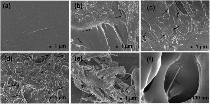
The surface morphology of the gel/MWCNT nanocomposite was investigated using a Field Emission Scanning Electron Microscope (FESEM). Fig. 3 shows FESEM images of the nanocomposites with different nanofiller concentrations. The ruptured surface of the pure gel sample seemed to be smooth, and no trace of MWCNT was seen. The presence of MWCNT was observed for the gel/MWCNT nanocomposites. A good dispersion of MWCNT was confirmed by the SEM images up to 0.02 wt% MWCNT nanocomposites. An increment in the density and a slight overlapping of the MWCNT fillers in the gel matrix were found in the highest MWCNT concentration sample. From Fig. 3(e) it was observed that the nanotubes form a cluster in the 0.05 wt% MWCNT containing the sample and this can be attributed to the agglomeration of nanotubes due to the van der Waals force.35 A similar morphological pattern was discovered for gel-based carbon nanotube composite films where CNTs form a bundle at higher concentrations.36 Also, MWCNTs were wrapped with gelatin by the different functional groups of its polymer chain during the sonication process which helps them to disperse evenly throughout the polymer matrix.16,37 Additionally, the roughness of the film surface increases with the concentration of MWCNTs. The increase in roughness means a larger surface area is created.3.3 Dielectric constant
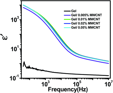
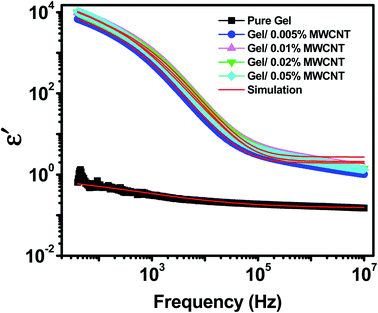
The variation of the real permittivity (ε′) of the nanocomposite as a function of the weight percentages of MWCNT nanofiller in gel matrix at room temperature is shown in Fig. 4. When the frequency is lower (up to 100 Hz) all nanocomposites show frequency-independent behavior as the space charge effect of interfacial polarization is responsible for the high dielectric permittivity in heterogeneous materials at low frequencies.38 This phenomenon occurs in systems made up of two or more constituents with varying electrical properties. The disparity in conductivities and permittivity of the constituents causes space-charge to gather at the interfaces of the elements. MWCNTs have a higher dielectric constant than the polymer matrix. Besides, MWCNT with its sp2 hybridized structures provides electrical conductivities. Under an applied electric field, electrons easily travel via the unsaturated pi bond due to its delocalization.39 But the insulating nature of the gel matrix forms a boundary around the MWCNTs. As a consequence, the MWCNTs in the polymer matrix turn into nanocapacitors.40 As a surfactant, the hydroxyl, carboxyl, and amino groups of gelatin cover the surface wall of MWCNT and provide homogeneous dispersion by reducing the possibilities of CNT aggregation.41 At low frequency (100 Hz) the dielectric constant of the pure gel sample (ε′ = 0.5) was found to be increased by five orders in magnitude due to the incorporation of just 0.02 wt% of MWCNT nanofiller (ε′ = 12![[thin space (1/6-em)]](https://www.rsc.org/images/entities/char_2009.gif) 000). At low frequencies, different types of polarizations such as dipolar, atomic and electronic polarizations may occur, but as the frequency rises, the dipoles become unable to keep up with the fast-changing field.42 As a result, the contribution of interfacial polarizations fades out first, followed by dipolar, atomic, and electronic polarizations, and the value of ε′ falls.43,44
000). At low frequencies, different types of polarizations such as dipolar, atomic and electronic polarizations may occur, but as the frequency rises, the dipoles become unable to keep up with the fast-changing field.42 As a result, the contribution of interfacial polarizations fades out first, followed by dipolar, atomic, and electronic polarizations, and the value of ε′ falls.43,44
3.4 Dielectric loss factor
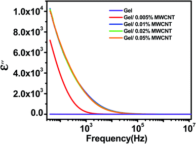
Fig. 5 exhibits how the imaginary permittivity of the dielectric loss factor (ε′′) of the nanocomposite varies with frequency as the concentration of the MWCNT nanofiller changes. The dielectric loss factor is related to the amount of energy necessary to align the dipoles in the field's direction. The values of ε′′ are found to be increased with the increase of nanofiller concentration and decrease as the applied frequencies increase. The observed imaginary permittivity (ε′′) may arise from different mechanism such as ionic conduction, interfacial, dipole, atomic, and electronic polarization mechanisms.38 Due to the difference in relaxation times between the CNT and gel, charge carriers from the external electrode relocate and aggregate at the interface when an electrical field is applied to the composite film. The large surface-to-volume aspect ratio of MWCNTs provides increased surface area for interfacial polarization to occur.2 Besides, defects play a significant role; there are several lattices and/or topological defects and interfaces that can cause changes in positive and negative space charge allocations, resulting in leakage current which enhances dielectric loss. The leakage current usually happens near percolation. MWCNTs reach the percolation threshold at relatively small concentrations, hence the inclusion of MWCNTs may result in a dielectric loss factor.45 The value of the dielectric loss was found to reduce rapidly as the frequency increases. This is due to the rapid movement of free charges through the nanocomposites.463.5 Fitting with Cole–Cole formula
When an AC electric field is applied, a material can undergo a variety of reorientation processes. Several theoretical models have been used to analyze the dielectric characteristics of different materials from the permittivity curve, based on the dispersions of relaxation time. For a single reorientation or monodispersed process, the Debye relaxation model is used to fully understand the material's dielectric properties.47–49 The real and imaginary parts of the complex dielectric constant are related in the Debye model as, ε*(ω) = ε′ − iε′′. Considering the frequency of the field, this relation can be written as, 47,50 where ε∞ is named as the dynamic permittivity which is recorded at the highest frequency limit of the material when it is unable to respond to the field, εs is called static permittivity, which is the limiting low-frequency permittivity. Here, ω is the angular frequency,
  and τ is the time characteristic of the relaxation phenomena.51
For materials with polydisperse relaxation processes, Cole and Cole refined the Debye formula called the Cole–Cole formula47 and express the complex dielectric constant as  where α is the dispersion coefficient and τ is the average relaxation time. With the help of this equation, the values of εs, ε∞, and α have been determined by simulating the experimental dielectric permittivity. The angular frequency at which the dielectric loss reaches its highest magnitude yielded the average relaxation time, τ52 using the relation
  Here the angular frequency, ω = 2πf, f being the frequency.47 The simulated data are presented in Fig. 6 and the different parameters obtained from the simulated curve are listed in Table 1. From the obtained fitting parameters, it can be concluded that the dielectric strength (Δε = εs − ε∞)47 increases due to the addition of MWCNT into the gel matrix suggesting a rise in the effective moment of the orienting unit due to the incorporation of nanofiller. For pure gel no relaxation peak was observed, the calculated relaxation time for sample gel/0.005 wt%, gel/0.01 wt%, gel/0.02 wt%, and gel/0.05 wt% MWCNT are 7.3 μs, 2.5 μs, 0.93 μs, and 31.8 μs respectively. The lowering of the relaxation period suggests that the polarization direction aligns with the AC field due to the incorporation of MWCNT.25 Furthermore, a smaller relaxation time indicates that the dielectric loss peaks at a higher frequency, evaluating the relaxation time is critical in the development of a material with stable dielectric characteristics. The observed large value of relaxation time for the nanocomposite with a higher concentration (0.05 wt%) of MWCNT can be attributed to the agglomeration of nanotubes which limits the interface regions by decrement of the interfacial area between polymer chains and nanoparticles. The thermal behavior of the nanocomposites also supports the dielectric performance (see ESI†).
| MWCNT concentration (wt%) | Static permittivity, εs | Dynamic permittivity, ε∞ | Dielectric strength, Δε = (εs − ε∞) | Relaxation time, τ0 (μs) | α |
|---|---|---|---|---|---|
| 0 | 0.78 | −415.15 | 415.93 | — | 1.11 |
| 0.005 | 2.10 | −2482.86 | 2484.96 | 7.3 | 1.37 |
| 0.01 | 2.71 | −2741.71 | 2744.42 | 2.5 | 1.38 |
| 0.02 | 1.93 | −5522.45 | 5524.38 | 0.93 | 1.36 |
| 0.05 | 2.21 | −5323.28 | 5325.49 | 31.8 | 1.34 |
3.6 Dielectric loss tangent
Fig. 7 shows the tangent loss (tan![[thin space (1/6-em)]](https://www.rsc.org/images/entities/char_2009.gif) δ) vs. frequency graph for varying concentrations of MWCNT in the gel matrix at room temperature. The tangent loss plots for all the nanocomposites show a single nearly Debye type relaxation peak.47 Initially, there is a rise in tangent loss as frequency increases reaching a maximum followed by a drop in the high-frequency range. In the low-frequency region the dominance of the ohmic resistive component, i.e., the friction of dipoles as they tend to align with the field may increase loss tangent. When the frequency of the electric field and that of the molecular rotation of the nanocomposite match then a peak is detected. At resonance, most of the field energy is dissipated, mostly in the form of heat.40 In the high-frequency regime, the dipoles are completely dormant in the field causing a reduction in the tangent loss. The components become frequency-independent at this point, whereas the capacitive part increases following the frequency. The relaxation peak moves more toward the high-frequency side in Fig. 7, indicating quicker energy transfer patterns between one regulating site to the other due to a reduction in relaxation time.53,54
δ) vs. frequency graph for varying concentrations of MWCNT in the gel matrix at room temperature. The tangent loss plots for all the nanocomposites show a single nearly Debye type relaxation peak.47 Initially, there is a rise in tangent loss as frequency increases reaching a maximum followed by a drop in the high-frequency range. In the low-frequency region the dominance of the ohmic resistive component, i.e., the friction of dipoles as they tend to align with the field may increase loss tangent. When the frequency of the electric field and that of the molecular rotation of the nanocomposite match then a peak is detected. At resonance, most of the field energy is dissipated, mostly in the form of heat.40 In the high-frequency regime, the dipoles are completely dormant in the field causing a reduction in the tangent loss. The components become frequency-independent at this point, whereas the capacitive part increases following the frequency. The relaxation peak moves more toward the high-frequency side in Fig. 7, indicating quicker energy transfer patterns between one regulating site to the other due to a reduction in relaxation time.53,54
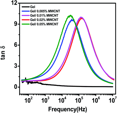 | ||
| Fig. 7 Variation of dielectric loss tangent of the gel/MWCNT nanocomposites as a function of applied frequency. | ||
To achieve excellent dielectric properties, a very well dispersion of CNTs throughout the polymer matrix is a must. Since MWCNTs tend to agglomerate at higher concentrations causing a higher value of dielectric loss tangent. The MWCNTs establish a conductive channel in the composites, making them conductive rather than capacitive. A leakage current developed as the composites became more conductive, causing some of the electrical energy to be changed into other energy (mainly thermal). When the MWCNT loading grew and a conductive pathway was constructed in the whole nanocomposite, the dielectric loss (tan![[thin space (1/6-em)]](https://www.rsc.org/images/entities/char_2009.gif) δ) of the composite rose owing to energy dissipation, resulting in a significant leakage current originating from the intimate connection between the MWCNTs.
δ) of the composite rose owing to energy dissipation, resulting in a significant leakage current originating from the intimate connection between the MWCNTs.
The conduction loss (which dominates at extremely low frequencies) and the polarization loss of space charges are the two basic types of dielectric loss.43,55 In general, the former contributes more to dielectric loss than the latter55 and as a result, the dielectric loss falls rapidly as frequency rises.
3.7 AC conductivity (σAC)
Fig. 8 shows the AC conductivity versus frequency curve for different concentrations of MWCNT nanofiller at room temperature. Depending on the frequency, the plot is divided into three separate zones. The low-frequency zone has a sharp rise in conductivity due to the lessening of electrode polarization, followed by a frequency-independent plateau region at an intermediate frequency (corresponding to maximal relaxation time) and a high-frequency dispersive region due to quick field reversal. All the samples show a comparatively lower conductivity at low frequencies, which might be owing to the dominating electrode polarization effect.52 The long-range conduction of the charge carriers is responsible for the almost plateau area in the middle frequency window, and the maximum relaxation peak slows down the rise in AC conductivity. The short-range ion movement (hopping) associated with AC conductivity causes the high-frequency dispersion area.54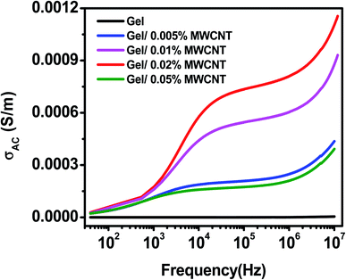 | ||
| Fig. 8 Variation of AC conductivity of the gel/MWCNT nanocomposites as a function of applied frequency. | ||
Interfacial polarization occurs between the electrode and the nanocomposite surface, as well as between the grains and other heterogeneous portions of the nanocomposite, at a lower frequency range. As the filler content increases, the bulk resistance of the composite reduces and the conduction process is controlled by inter-filler tunneling. MWCNT is fairly well dispersed randomly in the gelatin matrix composite. Moreover, the MWCNT may connect in part, and form a partly continuous random cluster. As a result, charges pass freely from one domain to another, resulting in higher conductivity. Among all nanocomposites, gel/0.02 wt% MWCNT nanocomposite showed high conductivity of 8 × 10⁻⁴ S m−1 at 10 kHz when compared to others. Whereas the pure gelatin exhibits a very low conductivity of about 0.5 × 10⁻⁵ S m−1 at the same frequency. AC conductivity is extremely low at very low frequencies and is due to the space-charge, interfacial, and dipolar polarization. The hopping of charge carriers in localized states, as well as the stimulation of charge carriers to the states in the conduction band, are the mechanism responsible for the increased frequency-dependent conductivity at higher frequencies.56,57
At higher concentrations, MWCNTs agglomerate due to van der Waals forces. The agglomeration hinders the creation of conducting paths throughout the polymer matrix resulting in the decrement of the AC conductivity of the gel/0.05% MWCNT nanocomposite.
3.8 Cole–Cole plot
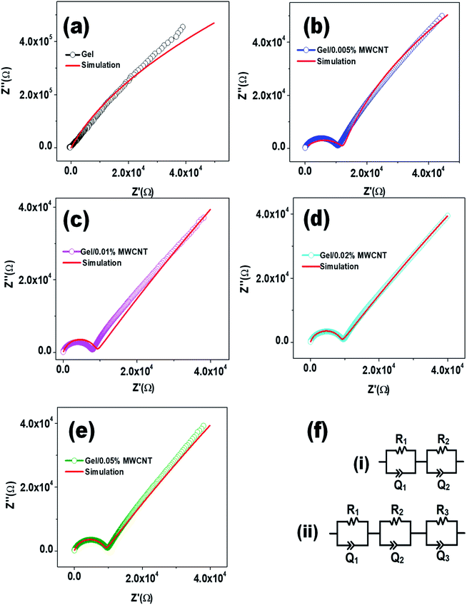
The Cole–Cole plot is obtained by plotting the imaginary impedance (Z′′) as a function of the real impedance (Z′) and is shown in Fig. 9. Z′ and Z′′ are related to the complex impedance of the composites by the relation Z = Z′ + iZ′′.58 Fig. 9 clearly shows that there is a curved arc at a higher frequency area followed by an inclined line at the lower frequency section due to a non-Debye type relaxation.59 In general, an equivalent RC parallel circuit is used to study the resistance (R) and capacitance (C) of a crystalline sample. On the complex plane, this RC element produces one semicircular arc that intersects the X-axis. The equivalent circuit for a bulk crystal with interfacial layers may be thought of as several parallel RC components linked successively. As the filler content increases, the intercept of the semicircular arcs on the real axis at the origin of the complex plane decreases, indicating a decrease in the sample's resistivity.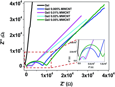 | ||
| Fig. 9 Cole–Cole plots of gel/MWCNT nanocomposites at room temperature for different amounts of filler incorporation (the high frequency region is shown in the image inset). | ||
Appropriate equivalent circuits were designed to fit the impedance spectra of the nanocomposites by utilizing the simulation for a quantitative investigation of the Cole–Cole plots of the gel/MWCNT nanocomposites. The corresponding circuit depicted in Fig. 10 best fits the simulated impedance spectra. The equivalent circuit for the nanocomposites is made up of two parallel circuits connected in series, each with resistance, R, and a capacitive constant phase element (CPE), Q. To obtain the best fitting, CPE is measured as:  where ZCPE is the constant phase angle impedance; Z0 is a constant; ω is the angular frequency; j is the imaginary component, and n is the exponential factor. CPE is comparable to a perfect capacitor, an inductance, or a pure resistance when n = 1, −1, or 0, respectively.60 Table 2 represents the estimated values of the different parameters of the equivalent circuits for the gel/MWCNT nanocomposite.
| MWCNT concentration (wt%) | Electrode res., R1 (kΩ) | Electrode cap., Q1 (nF) | Grain boundary res., R2 (kΩ) | Grain boundary cap., Q2 (nF) | Grain res., R3 (kΩ) | Grain cap., Q3 (μF) |
|---|---|---|---|---|---|---|
| 0 | 65 | 0.002 | 5935 | 0.012 | — | — |
| 0.005 | 9.45 | 0.18 | 972 | 8.42 | 12.43 | 0.23 |
| 0.01 | 7.43 | 46.13 | 316 | 232 | 9.52 | 0.70 |
| 0.02 | 5.14 | 231.5 | 261 | 540 | 0.032 | 23.25 |
| 0.05 | 6.03 | 1.08 | 294 | 0.142 | 7.38 | 0.21 |
Two different equivalent circuits were used for the simulation of the pure gel sample (i) and the gel/MWCNT sample (ii). The circuit for the pure gel sample contains two parallel RC components connected in series. Whereas the gel/MWCNT sample contains a series connection of a third RC component. The first RC parallel circuit originates from the electrode's contribution, mainly depending on the element of the electrode. R1 is the electrode resistance and Q1 is the electrode capacitive element. The second parallel part of the circuit contains the grain boundary resistance R2 and the grain boundary capacitive element Q2. They refer to the region separating two conductive regions. The grain boundary resistance displays a huge reduction of about three orders of magnitude from 6 MΩ for the gel sample to 261 kΩ for the gel/0.02 wt% MWCNT sample. The third parallel circuit of the equivalent circuit for the gel/MWCNT nanocomposites refers to the grain i.e., the conductive parts formed between the incorporated MWCNTs in the gel matrix. From Fig. 10(a) it is observed that there is no such region or grain formed in the pure gel sample. Later with the addition of MWCNT into the gel matrix grains were formed. With the increase of MWCNT contents, the grain resistance R3 decreases from 12.43 kΩ to 0.032 kΩ, and the value of the capacitive component of the grain Q3 increases. The variation of the grain and grain boundary elements show a similar trend which confirms a less reactive and more capacitive behavior of the nanocomposites. However, the gel/0.05% MWCNT nanocomposite does not follow this trend. That is maybe due to the agglomeration of CNTs in higher concentrations.
A similar trend was found in the thermal analysis of these nanocomposites (provided in the ESI section†).
3.9 Charge transport mechanism
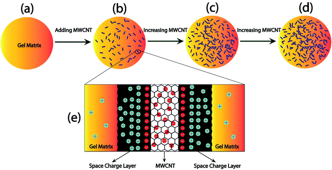
Fig. 11 demonstrated a model that can be used to comprehend the charge transport mechanism using the data obtained from the equivalent circuit assessment of the complex impedance spectra. Fig. 11(a) shows the gel matrix which does not produce a substantial charge deposit area. When MWCNTs are introduced into the gel matrix, as shown in Fig. 11(b), the MWCNT offers a greater surface area for charge collection, increasing the material's capacitance (the space charge effect). Since MWCNTs are dispersed into the nanocomposite, it is possible to attain a greater surface area, i.e., a higher capacitance value, with even a small number of MWCNTs. The increased number of MWCNTs, as shown in Fig. 11(c), contributes to a greater increase in surface area, resulting in a larger capacitance value for the materials up to 0.02 wt% of MWCNT. This also aids in comprehending the nanocomposite material's enormous dielectric constant. The dielectric constant increases dramatically as the capacitive area increases. Furthermore, the addition of MWCNTs to the gel matrix improves electron transport throughout the matrix. Electrons moved from one MWCNT to another by various mechanisms including tunneling, hopping, leaping, and so on. When the amount of MWCNTs is increased few of them might come closer and form a conductive network across the polymer matrix.For higher nanofiller concentration (0.05 wt% MWCNT), MWCNTs get agglomerated due to the van der Waals interaction among them. This cluster of MWCNTs which is shown in Fig. 11(d) tends to make the materials more conductive rather than capacitive and the capacitance of this nanocomposite got declined. It is also the reason for the large dielectric loss of the material as the probability of the leakage current increases.
Fig. 11(e) shows the charge development between the MWCNT nanofiller and the gel interface. The non-hybridized electrons of the carbon of MWCNT participate in the electron conduction when a voltage is applied to the nanocomposite material, but the insulating gel matrix prevents this. As a result, electrons are collected at the contact surface. The gel matrix, on the other hand, is less conductive, and the positive charge carriers from the trapped water molecules congregate near the negatively charged MWCNT wall. As a result, a nano capacitive layer is formed in this area. As the number of MWCNTs rises, so does the number of capacitive areas, which results in an increase in capacitance. However, when the MWCNT concentration is large enough, electrons may be carried across CNTs; the conductive region, i.e. grains, while bypassing the gel matrix; and the high resistive region, i.e. grain borders.
4. Conclusion
Biodegradable gel/MWCNT nanocomposites with different concentrations of MWCNT were successfully prepared by a facile solution casting method and their structural, surface morphological and dielectric properties were observed. A significantly large dielectric constant together with small dielectric loss is observed due to the interfacial polarization between the polymer and the filler. A significant improvement in the performance parameter of the dielectric behavior of the nanocomposites was obtained using the Cole–Cole model. The simulated data obtained from the analysis of the complex impedance spectra reveal a decrease in the grain barrier resistance together with an increase in the capacitive element from 0 to 23.25 μF due to the formation of nanocapacitive regions due to the well dispersion of MWCNTs into the polymer matrix. Furthermore, a model has been proposed to elucidate the improved dielectric performance of the MWCNT reinforced nanocomposites by explaining the charge transport mechanism. This biofriendly nanocomposite with excellent dielectric properties might find its way to use in fabrication of next-generation, smart and flexible energy storage devices.Conflicts of interest
There are no conflicts to declare.Acknowledgements
R. B. A. and M. R. I. acknowledge the financial support provided by the Committee for Advanced Studies and Research (CASR), Bangladesh University of Engineering and Technology, Bangladesh, under grant reference no. DAERS/R-01/CASR-337th/2021 (Meeting 337, Resolution:72, Date: 16/01/2021).References
- N. Suderman, M. I. N. Isa and N. M. Sarbon, The effect of plasticizers on the functional properties of biodegradable gelatin-based film: a review, Food Biosci., 2018, 24(September 2017), 111–119, DOI:10.1016/j.fbio.2018.06.006.
- M. M. Rahman, Preparation of Carbon Nanotube Reinforced Gelatin-Chitosan-Hydroxyapatite Biocomposite for Bone Tissue Engineering, Open Access J. Biomed. Eng. Biosci., 2018, 1(3), 66–72, DOI:10.32474/oajbeb.2018.01.000113.
- N. Golafshan, M. Kharaziha and M. Fathi, Tough and conductive hybrid graphene-PVA: alginate fibrous scaffolds for engineering neural construct, Carbon, 2017, 111, 752–763, DOI:10.1016/j.carbon.2016.10.042.
- A. Sayah, et al., Electrochemical synthesis of polyaniline-exfoliated graphene composite films and their capacitance properties, J. Electroanal. Chem., 2018, 818(April), 26–34, DOI:10.1016/j.jelechem.2018.04.016.
- M. Amjadi, K. U. Kyung, I. Park and M. Sitti, Stretchable, Skin-Mountable, and Wearable Strain Sensors and Their Potential Applications: A Review, Adv. Funct. Mater., 2016, 26(11), 1678–1698, DOI:10.1002/adfm.201504755.
- J. H. Lin, Z. I. Lin, Y. J. Pan, C. L. Huang, C. K. Chen and C. W. Lou, Polymer composites made of multi-walled carbon nanotubes and graphene nano-sheets: effects of sandwich structures on their electromagnetic interference shielding effectiveness, Composites, Part B, 2016, 89, 424–431, DOI:10.1016/j.compositesb.2015.11.014.
- X. Ma, et al., A robust asymmetric porous SWCNT/Gelatin thin membrane with salt-resistant for efficient solar vapor generation, Appl. Mater. Today, 2020, 18, 100459, DOI:10.1016/j.apmt.2019.100459.
- Y. Ma, et al., Robust and Antibacterial Polymer/Mechanically Exfoliated Graphene Nanocomposite Fibers for Biomedical Applications, ACS Appl. Mater. Interfaces, 2018, 10(3), 3002–3010, DOI:10.1021/acsami.7b17835.
- Q. Li, Q. Xue, L. Hao, X. Gao and Q. Zheng, Large dielectric constant of the chemically functionalized carbon nanotube/polymer composites, Compos. Sci. Technol., 2008, 68(10–11), 2290–2296, DOI:10.1016/j.compscitech.2008.04.019.
- A. K. Das, A. Mukherjee, K. Baba, R. Hatada, R. Bhowmik and A. K. Meikap, Current-Voltage Hysteresis Behavior of PVA-Assisted Functionalized Single-Walled Carbon Nanotube Free-Standing Film, J. Phys. Chem. C, 2018, 122(51), 29094–29105, DOI:10.1021/acs.jpcc.8b08875.
- K. Müller, et al., Review on the processing and properties of polymer nanocomposites and nanocoatings and their applications in the packaging, automotive and solar energy fields, Nanomaterials, 2017, 7(4), 74, DOI:10.3390/nano7040074.
- M. H. Mousa, Y. Dong and I. J. Davies, Recent advances in bionanocomposites: preparation, properties, and applications, Int. J. Polym. Mater. Polym. Biomater., 2016, 65(5), 225–254, DOI:10.1080/00914037.2015.1103240.
- L. Zhang, Z. Liu, G. Cui and L. Chen, Biomass-derived materials for electrochemical energy storages, Prog. Polym. Sci., 2015, 43, 136–164, DOI:10.1016/j.progpolymsci.2014.09.003.
- S. I. Mollik, M. H. Ahmad, R. B. Alam, M. W. Bari and M. R. Islam, Improved thermal, mechanical, and electrochemical performance of bio-degradable starch/reduced graphene oxide nanocomposites, AIP Adv., 2021, 11, 095312, DOI:10.1063/5.0059146.
- S. I. Mollik, R. B. Alam and M. R. Islam, Significantly improved dielectric properties of bio-compatible starch/reduced graphene oxide nanocomposites, Synth. Met., 2020,(September), 116624, DOI:10.1016/j.synthmet.2020.116624.
- Y. Li, R. Li, X. Fu, Y. Wang and W. H. Zhong, A bio-surfactant for defect control: multifunctional gelatin coated MWCNTs for conductive epoxy nanocomposites, Compos. Sci. Technol., 2018, 159, 216–224, DOI:10.1016/j.compscitech.2018.03.001.
- M. P. Das, P. R. Suguna, K. Prasad, J. V. Vijayalakshmi and M Renuka, Extraction and Characterization of Gelatin: a Functional Biopolymer, Int. J. Pharm. Pharm. Sci., 2017, 9(9), 239, DOI:10.22159/ijpps.2017v9i9.17618.
- R. B. Alam, M. H. Ahmad and M. R. Islam, Bio-inspired gelatin/single-walled carbon nanotube nanocomposite for transient electrochemical energy storage: an approach towards eco-friendly and sustainable energy system, Heliyon, 2021, 7(7), e07468, DOI:10.1016/j.heliyon.2021.e07468.
- S. Datta, M. Y. Fard and A. Chattopadhyay, High-Speed Surfactant-Free Fabrication of Large Carbon Nanotube Membranes for Multifunctional Composites, J. Aerosp. Eng., 2016, 29(3), 04015060, DOI:10.1061/(asce)as.1943-5525.0000558.
- V. D. Punetha, et al., Functionalization of carbon nanomaterials for advanced polymer nanocomposites: a comparison study between CNT and graphene, Prog. Polym. Sci., 2017, 67, 1–47, DOI:10.1016/j.progpolymsci.2016.12.010.
- K. Duan, L. Li, F. Wang, W. Meng, Y. Hu and X. Wang, Importance of interface in the coarse-grained model of CNT/epoxy nanocomposites, Nanomaterials, 2019, 9(10), 1–18, DOI:10.3390/nano9101479.
- B. Fan, Y. Liu, D. He and J. Bai, Achieving polydimethylsiloxane/carbon nanotube (PDMS/CNT) composites with extremely low dielectric loss and adjustable dielectric constant by sandwich structure, Appl. Phys. Lett., 2018, 112, 052902, DOI:10.1063/1.5016543.
- X. Liao, et al., Flexible hdC-G reinforced polyimide composites with high dielectric permittivity, Composites, Part A, 2017, 101, 50–58, DOI:10.1016/j.compositesa.2017.06.011.
- Y. J. Xiao, et al., Largely Enhanced Thermal Conductivity and High Dielectric Constant of Poly(vinylidene fluoride)/Boron Nitride Composites Achieved by Adding a Few Carbon Nanotubes, J. Phys. Chem. C, 2016, 120(12), 6344–6355, DOI:10.1021/acs.jpcc.5b12651.
- B. Wang, et al., Two-layer materials of polyethylene and a carbon nanotube/cyanate ester composite with high dielectric constant and extremely low dielectric loss, Carbon, 2013, 54, 224–233, DOI:10.1016/j.carbon.2012.11.033.
- K. Zheng, et al., International Journal of Biological Macromolecules antimicrobial, antioxidant and structural properties, Int. J. Biol. Macromol., 2019, 135, 344–352, DOI:10.1016/j.ijbiomac.2019.05.151.
- C. Huang, X. Qian and R. Yang, Thermal conductivity of polymers and polymer nanocomposites, Mater. Sci. Eng., R, 2018, 132(July), 1–22, DOI:10.1016/j.mser.2018.06.002.
- B. M. Shafiee, R. Torkaman, M. Mahmoudi, R. Emadi and E. karamian, An improvement in corrosion resistance of 316L AISI coated using PCL-gelatin composite by dip-coating method, Prog. Org. Coat., 2019, 130(January), 200–205, DOI:10.1016/j.porgcoat.2019.01.057.
- M. T. Byrne and Y. K. Guin'Ko, Recent advances in research on carbon nanotube - polymer composites, Adv. Mater., 2010, 22(15), 1672–1688, DOI:10.1002/adma.200901545.
- P. Subbalakshmi and N. Veeraiah, Study of CaO-WO3-P2O5 glass system by dielectric properties, IR spectra and differential thermal analysis, J. Non-Cryst. Solids, 2002, 298(1), 89–98, DOI:10.1016/S0022-3093(01)01039-0.
- N. Cebi, M. Z. Durak, O. S. Toker, O. Sagdic and M. Arici, An evaluation of Fourier transforms infrared spectroscopy method for the classification and discrimination of bovine, porcine and fish gelatins, Food Chem., 2016, 190, 1109–1115, DOI:10.1016/j.foodchem.2015.06.065.
- M. S. Hoque, S. Benjakul and T. Prodpran, Properties of film from cuttlefish (Sepia pharaonis) skin gelatin incorporated with cinnamon, clove and star anise extracts, Food Hydrocolloids, 2011, 25(5), 1085–1097, DOI:10.1016/j.foodhyd.2010.10.005.
- J. Hossan, M. A. Gafur, M. R. Kadir and M. Mainul, Preparation and Characterization of Gelatin-Hydroxyapatite Composite for Bone Tissue Engineering, Int. J. Eng. Technol. Sci., 2014, 57(01), 113–122 Search PubMed.
- K. S. Salem, M. M. Lubna, A. M. Rahman, M. Nurnabi, R. Islam and M. A. Khan, The effect of multiwall carbon nanotube additions on the thermo-mechanical, electrical, and morphological properties of gelatin-polyvinyl alcohol blend nanocomposite, J. Compos. Mater., 2015, 49(11), 1379–1391, DOI:10.1177/0021998314534704.
- H. Y. Miao, J. H. Liu, L. Saravanan, C. W. Tsao and J. W. Pan, Dielectric property determination of hybrid Al2O3-filled MWCNT buckypaper by the rectangular cavity perturbation technique, Appl. Phys. A: Mater. Sci. Process., 2015, 119(1), 211–217, DOI:10.1007/s00339-014-8950-x.
- M. R. Islam, S. M. N. S. Pias, R. B. Alam and S. I. Khondaker, Enhanced electrochemical performance of solution-processed single-wall carbon nanotube reinforced polyvinyl alcohol nanocomposite synthesized via solution-cast method, Nano Express, 2020, 1(3), 030013, DOI:10.1088/2632-959x/abc050.
- B. Düzkan, B. Ö. Uysal and Ö. Pekcan, Surfactant-free one-step fabrication of gelatin/PAAm/MWCNT composites for biomedical applications, Polym. Bull., 2021, 79, 1597–1614, DOI:10.1007/s00289-021-03574-4.
- S. Choudhary and R. J. Sengwa, Effects of different inorganic nanoparticles on the structural, dielectric and ion transportation properties of polymers blend based nanocomposite solid polymer electrolytes, Electrochim. Acta, 2017, 247, 924–941, DOI:10.1016/j.electacta.2017.07.051.
- C. L. Poh, M. Mariatti, A. F. M. Noor, O. Sidek, T. P. Chuah and S. C. Chow, Dielectric properties of surface treated multi-walled carbon nanotube/epoxy thin film composites, Composites, Part B, 2016, 85, 50–58, DOI:10.1016/j.compositesb.2015.09.024.
- J. K. Yuan, S. H. Yao, Z. M. Dang, A. Sylvestre, M. Genestoux and J. Bai, Giant dielectric permittivity nanocomposites: realizing true potential of pristine carbon nanotubes in polyvinylidene fluoride matrix through an enhanced interfacial interaction, J. Phys. Chem. C, 2011, 115(13), 5515–5521, DOI:10.1021/jp1117163.
- S. W. Kim, et al., Surface modifications for the effective dispersion of carbon nanotubes in solvents and polymers, Carbon, 2012, 50(1), 3–33, DOI:10.1016/j.carbon.2011.08.011.
- R. J. Sengwa and S. Choudhary, Dielectric and electrical properties of PEO–Al2O3 nanocomposites, J. Alloys Compd., 2017, 701, 652–659, DOI:10.1016/j.jallcom.2017.01.155.
- S. Bonardd, V. Moreno-Serna, G. Kortaberria, D. D. Díaz, A. Leiva and C. Saldías, Dipolar glass polymers containing polarizable groups as dielectric materials for energy storage applications. A minireview, Polymers, 2019, 11(2), 1–10, DOI:10.3390/polym11020317.
- S. Zhang, H. Su, C. S. Tan, T. K. S. Wong and R. J. W. Teo, Dielectric relaxation in AC powder electroluminescent devices, Solid State Commun., 2017, 250(October 2016), 53–56, DOI:10.1016/j.ssc.2016.11.010.
- P. Fan, L. Wang, J. Yang, F. Chen and M. Zhong, Graphene/poly(vinylidene fluoride) composites with high dielectric constant and low percolation threshold, Nanotechnology, 2012, 23, 365702, DOI:10.1088/0957-4484/23/36/365702.
- S. Yao, J. Yuan, H. al Mehedi, E. Gheeraert and A. Sylvestre, Carbon nanotube forest based electrostatic capacitor with excellent dielectric performances, Carbon, 2017, 116, 648–654, DOI:10.1016/j.carbon.2017.02.043.
- K. S. Cole and R. H. Cole, Dispersion and absorption in dielectrics I. Alternating current characteristics, J. Chem. Phys., 1941, 9(4), 341–351, DOI:10.1063/1.1750906.
- G. M. Tsangaris, G. C. Psarras and N. Kouloumbi, Electric modulus and interfacial polarization in composite polymeric systems, J. Mater. Sci., 1998, 33(8), 2027–2037, DOI:10.1023/A:1004398514901.
- S. Havriliak and S. Negami, A complex plane analysis of α-dispersions in some polymer systems, J. Polym. Sci., Part C: Polym. Symp., 2007, 14(1), 99–117, DOI:10.1002/polc.5070140111.
- B. Atawa, et al., Molecular mobility of amorphous N-acetyl-α-methylbenzylamine and Debye relaxation evidenced by dielectric relaxation spectroscopy and molecular dynamics simulations, Phys. Chem. Chem. Phys., 2019, 21(2), 702–717, 10.1039/c8cp04880k.
- D. W. Davidson and R. H. Cole, Dielectric relaxation in glycerine [11], J. Chem. Phys., 1950, 18(10), 1417, DOI:10.1063/1.1747496.
- X. Jiang, X. Zhao, G. Peng, W. Liu, K. Liu and Z. Zhan, Investigation on crystalline structure and dielectric relaxation behaviors of hot pressed poly(vinylidene fluoride) film, Curr. Appl. Phys., 2017, 17(1), 15–23, DOI:10.1016/j.cap.2016.10.011.
- K. Górska, A. Horzela, L. Bratek, G. Dattoli and K. A. Penson, The Havriliak-Negami relaxation and its relatives: the response, relaxation and probability density functions, J. Phys. A: Math. Theor., 2018, 51, 135202, DOI:10.1088/1751-8121/aaafc0.
- K. Tsuji, H. S. Han, S. Guillemet-Fritsch and C. A. Randall, Dielectric relaxation and localized electron hopping in colossal dielectric (Nb,In)-doped TiO2 rutile nanoceramics, Phys. Chem. Chem. Phys., 2017, 19(12), 8568–8574, 10.1039/c7cp00042a.
- P. K. Tripathi, A. Kumar and K. K. Pandey, Dielectric Study of Multiwall Carbon Nanotube Dispersed Nematic Liquid Crystal Mixture, Mater. Today: Proc., 2018, 5(3), 9182–9186, DOI:10.1016/j.matpr.2017.10.041.
- J. Huang, Q. Long, S. Xiong, L. Shen and Y. Wang, Application of poly (4-styrenesulfonic acid-co-maleic acid) sodium salt as novel draw solute in forward osmosis for dye-containing wastewater treatment, Desalination, 2017, 421(March), 40–46, DOI:10.1016/j.desal.2017.01.039.
- A. S. Roy, S. Gupta, S. Sindhu, A. Parveen and P. C. Ramamurthy, Dielectric properties of novel PVA/ZnO hybrid nanocomposite films, Composites, Part B, 2013, 47, 314–319, DOI:10.1016/j.compositesb.2012.10.029.
- M. M. Altarawneh, G. A. Alharazneh and O. Y. Al-Madanat, Dielectric properties of single wall carbon nanotubes-based gelatin phantoms, J. Adv. Dielectr., 2018, 8(2), 1–6, DOI:10.1142/S2010135X18500108.
- C. Grosse, A program for the fitting of Debye, Cole-Cole, Cole-Davidson, and Havriliak-Negami dispersions to dielectric data, J. Colloid Interface Sci., 2014, 419, 102–106, DOI:10.1016/j.jcis.2013.12.031.
- K. Chybczyńska, E. Markiewicz, A. Grząbka-Zasadzińska and S. Borysiak, Dielectric, magnetic, and mechanical properties of composites consisting of biopolymer chitosan matrix and hybrid spinel/cellulose filler, Ceram. Int., 2019, 45(7), 9468–9476, DOI:10.1016/j.ceramint.2018.09.042.
Footnote |
| † Electronic supplementary information (ESI) available. See https://doi.org/10.1039/d2ra01508k |
| This journal is © The Royal Society of Chemistry 2022 |

