DOI:
10.1039/D2RA01407F
(Paper)
RSC Adv., 2022,
12, 12436-12445
Numerical analysis on a catalytic pyrolysis reactor design for plastic waste upcycling using CFD modelling†
Received
3rd March 2022
, Accepted 15th April 2022
First published on 25th April 2022
Abstract
Catalytic pyrolysis technologies are a current trend to address plastic waste upcycling, offering lower energy consumption and higher value products when compared to conventional thermal pyrolysis. In this study, catalytic pyrolysis of HDPE was simulated using computational fluid dynamics (CFD) in order to analyze the physical behaviour of a designed fluidized bed reactor unit on a pilot scale. Dimensionless numbers were used for heat and mass transfer assessment to provide useful insights for the scale-up of this technology. A fluidized bed reactor configuration was selected for its effective heat/mass transfer and compatibility with ZSM-5 catalyst. Calculations were performed on a set of temperatures (300–500 °C) and feed rates (0.5–1 kg m−2 s−1) to determine the best performing conditions. Tradeoffs between conversion, production rate and heat consumption were discussed. The key results of this study indicate that a feed rate of 1 kg m−2 s−1 at 500 °C yields the best gasoline production while consuming the lowest amount of energy per kilogram of product.
Introduction
Plastic waste in major cities such as Lima and Callao (Peru) are generated at a significant rate of 886 tons per day, which makes it comparable to the mass feedstock of small petroleum refineries (6500 BPD). According to the Ministry of Environment, only 4% is recycled while the rest is disposed of as municipal waste, increasing the environmental impact of these residues.1,2 In the last decades, technological advancements to address this issue have led to the development of novel processes to produce fuels through thermal, catalytic and biological methods.3 This study aimed to analyse the physical behaviour of a fluidized bed reactor unit for HDPE upcycling on a pilot scale (≈1.08 kg min−1), in order to establish a basis for the scaling of this technology. This highly detailed physical and mathematical model is meant to provide useful insights for scale-up.
Through the process of pyrolysis, the production of liquid oil, gases and char is achieved. This technology is mature and extensively used for biomass and plastic processing.4 It consists in the thermal degradation of plastics in a reactor at high temperatures (300–900 °C) in the absence of oxygen, where the heterogenous mixture of hydrocarbons is produced.5 Several types of plastics may be used as feedstock, such as PS, PE, PP, PVC and PET. Hence, the kinetic model of the reactions varies according to the composition. In some cases, hazardous substances are produced, such as chlorine gas, when PVC is processed. For this reason, an additional reactor or separation unit may be required to eliminate the undesired components.6
In this study, HDPE was considered for this analysis using kinetic modelling information from experimental data.7–9
In order to improve the process efficiency, selectivity, reduction of the retention time and operate under relatively mild conditions, a wide variety of catalysts have been tested by the literature. The most used are ZSM-5, Y-zeolite, FCC and MCM-41.10 As a result, desired reactions have a higher yield. These include cracking, oligomerization, cyclization, aromatization and isomerization reactions.11 The product consists of heavy fraction which exhibits similar properties to those of conventional gasoline.9 and the light fraction contains hydrocarbons ranging from methane to butane, including olefins. Products yield strongly depends on the operating conditions and catalyst.12
To achieve accurate modelling and results catalytic pyrolysis processing, CFD analysis proved to be highly convenient, since it incorporates transport phenomena, fluid-solid interaction and kinetic modelling to solve steady-state simulations for various scenarios (comprised by different feed fluxes and temperatures). CFD has been widely used for the analysis of plastic waste, biomass and mixed solid waste pyrolysis.13–22 In a few cases, catalytic pyrolysis has been investigated as a fixed bed reactor setup.23 No examples of CFD analysis for catalytic pyrolysis with ZSM-5 catalyst on a fluidized bed were found in literature, to the best of our knowledge. For this study, a fluidized solid phase modelling strategy was used, instead of a discrete element method, to save computational resources. This reactor setup was proposed due to its advantages in terms of heat transfer, particle size flexibility, compatibility with solid catalysts and scale-up flexibility.24 The model was tested under a set of temperatures (300 to 500 °C) and feed rates (0.5 to 1 kg m−2 s−1). Contour profiles for variables such as flow velocity, temperature and composition were obtained. To rate performance at each scenario, the analysis considered yield, energy consumption, heat and mass transfer.
Methodology
Reactor configuration and operating parameters
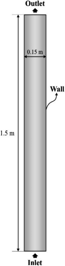
The modelled reactor was a cylinder of uniform diameter. Diameter and height were 0.15 m and 1.5 m, respectively. In order to provide adequate heat and mass transfer, the catalyst is fluidized through the injection of the gaseous phase (feed + inert) from the bottom of the reactor, as shown in Fig. 1.
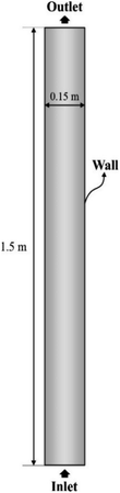 |
| | Fig. 1 Reactor layout and dimensions. | |
To promote upward flow, the outlet of the system was placed at the top of the reactor vessel. Catalyst used was ZSM-5, due to its experimental selectivity towards desired reactions.25 A particle size of 30 μm was selected to provide a favourable and well-behaved fluidization according to Geldart's powder classification. Operating parameters and physical properties used for the experiments can be found on Table 1.
Table 1 Operating parameters for the reactor model and relevant physical properties of the feedstock
| Parameter |
Value |
Ref. |
| Inlet mole fractions |
|
|
| Hydrocarbon feed (C12+) |
0.5 |
|
| N2 |
0.5 |
|
| Inlet temperature (°C) |
300–500 |
6, 30–33 |
| Operating pressure (Pa) |
101, 325 |
|
| Inlet mass flux (kg m−2 s−1) |
0.5–1 |
31–34 |
| Feed to catalyst mass ratio |
10![[thin space (1/6-em)]](https://www.rsc.org/images/entities/char_2009.gif) :1 :1 |
35 |
| Catalyst particle size (μm) |
30 |
34 and 36 |
| Catalyst bulk density (kg m−3) |
720 |
37 |
| Thermal conductivity of the catalyst (W m−1 K−1) |
3.3 |
38 |
| Specific heat of the catalyst (J kg−1 K−1) |
935 |
39 |
The reactor vessel material was selected as AISI 304 grade stainless-steel. This constitution allows the reactor to withstand high temperatures up to 815 °C, as well as corrosion.26 For practical purposes, this material was defined only as the surface of the walls and no solid was simulated. If this was the case, a meshing procedure would have been carried out for the solid wall with a given thickness, potentially in the range of 0.2–0.5 cm.27 With this modification, the total number of elements would be up to 12% higher, based on the increase of the volume. The computational time would increase proportionally.
The potential impact of the wall material on the gas properties was investigated. Literature suggests that heat loss by conduction in reactors is relevant when operating at micro scales, due to the surface-to-volume ratio.28,29 Therefore, effects on thermal and fluid properties of the gas due to wall material at this operating size are negligible.
Kinetic model for HDPE catalytic pyrolysis using ZSM-5 catalyst
The kinetic model is based on studies by Khedri and Artetxe et al.8,9 on the catalytic pyrolysis of HDPE using ZSM-5 catalyst. This approach approximates the reaction mechanism to the scheme depicted in Fig. 2, assuming a thermal pyrolysis pre-treatment to maintain a homogenous gaseous behaviour in the reaction system.10 Gaseous feed is composed of a C12+ hydrocarbon mixture and the products are split into two groups: C2–4 (olefins and alkanes) and C5–11 fraction (non-aromatics and aromatics). In this study, the heavier fraction is considered the most valuable, since it has a commercial value as gasoline.
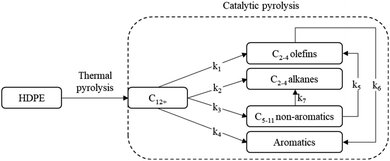 |
| | Fig. 2 Kinetic scheme for the reaction. Adapted from Artetxe et al.8 | |
The reaction rate of specie i in reaction j is defined as follows:
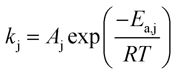
Rate constant kj is computed using Arrhenius' law:
| |
 | (2) |
where the activation energy
Ea,j and pre-exponential factor
Aj take the values shown on
Table 2.
8,9
Table 2 Reactions and kinetic parameters8,9
| Reaction |
Rate constant |
Ea,j (kJ mol−1) |
Aj |
| C12+ → C2–4 (olefins) |
k1 |
24 |
1.654 × 10⁸ |
| C12+ → C2–4 (alkanes) |
k2 |
| C12+ → C5–11 (non-aromatics) |
k3 |
| C12+ → C5–11 (aromatics) |
k4 |
| C5–11 (non-aromatic) → C2–4 (olefins) |
k5 |
57 |
| C5–11 (non-aromatic) → C2–4 (alkanes) |
k7 |
| C2–4 (olefins) → C5–11 (aromatics) |
k6 |
54 |
CFD model
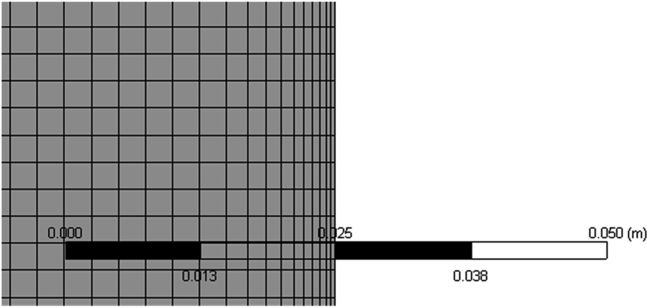
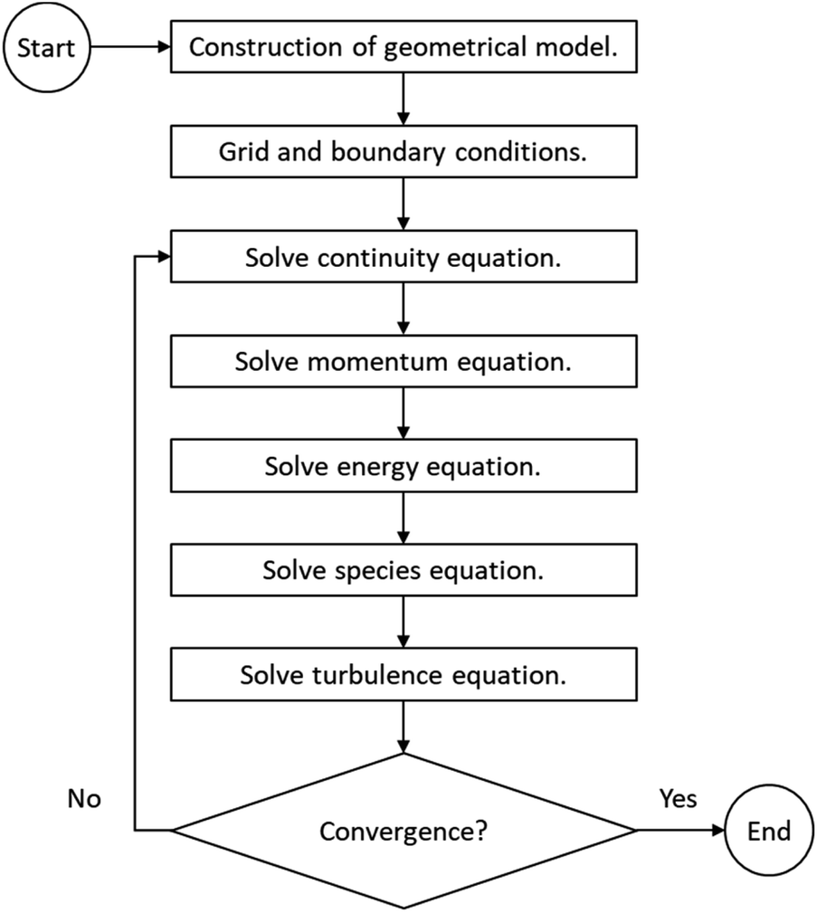
A two-dimensional, steady-state model was used for the simulation, considering a longitudinal cut of the reactor to save computation time. The mesh was elaborated with a structured design and a maximum size of 2.5 × 10⁻³ m per cell, for which grid dependence was tested to be negligible (check ESI S.1†). Also, an inflation method was used to refine the size near the walls in order to increase the accuracy of the boundary layer (Fig. 3). Total number of elements summed 43200. The simulations were configured on ANSYS Fluent v.18.1 software and run using design point tool on an Intel Core i7 CPU with 6 cores and 24 GB of RAM, which was sufficient for this study. For turbulence modelling, the k-epsilon realizable model was employed. A convergence criterion was determined for each residual of the conservation equations and is presented in the ESI S.2.†
 |
| | Fig. 3 Inflation method close up view. | |
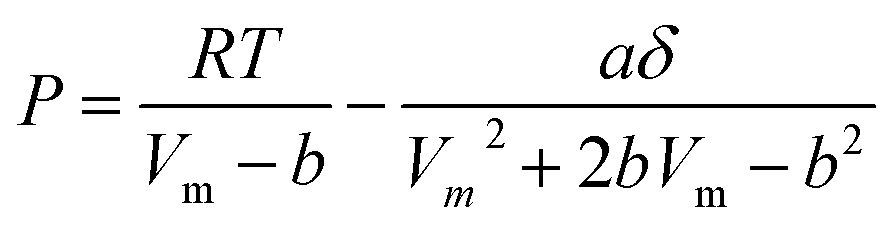
Thermodynamic properties were calculated through the Peng–Robinson equation of state (eqn (3)).40 This model estimated the values of temperature, pressure and specific volume for each component in the gas mixture.
| |
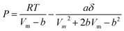 | (3) |
where
a,
δ,
b, are specific constants for each gaseous specie.
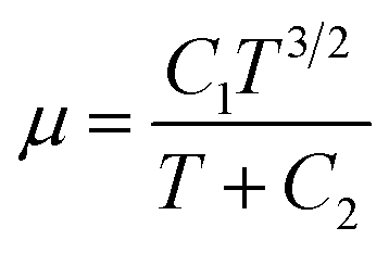
For the fluid physical model, viscosity was calculated as a function of the local temperature for each component throughout the domain using Sutherland's law (eqn (4)).41
| |
 | (4) |
where
C1 and
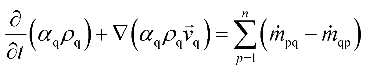
C2 are specific constants for each fluid that were calculated from a process simulation software database. The Eulerian method for multiphase flow modelling was used. Two phases were defined: a fluid mixture which contains reactant and products (gas phase) and the ZSM-5 catalyst (solid phase). Mass, momentum and energy conservation are computed through the set of eqn (5)–(8) on
Table 3, which are derived from the Navier–Stokes equations.
42 The algorithm for equation solving is presented in
Fig. 4.
Table 3 Navier Stokes conservation equations
| Conservation law |
Equation |
| Mass |
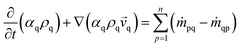 |
(5) |
| Fluid-solid momentum |
 |
(6) |
| Species |
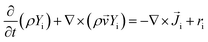 |
(7) |
| Energy |
 |
(8) |
 |
| | Fig. 4 Model solving algorithm. | |
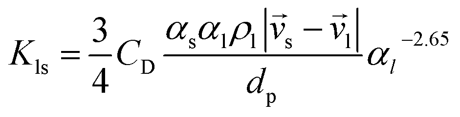
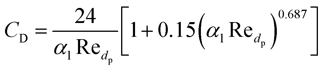
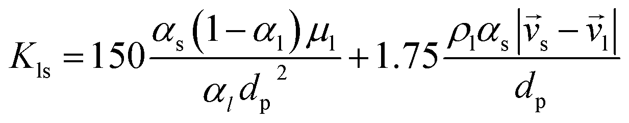
Gidaspow's approach was used for the fluid–solid exchange coefficient Kls model, as suggested by the ANSYS Fluent Theory Guide for fluidized bed systems.42 When αl > 0.8:
| |
 | (9) |
where l is a fluid phase, s is a solid phase and
dp is the particle diameter. Drag coefficient
CD equals:
| |
 | (10) |
Alternatively, when αl ≤ 0.8:
| |
 | (11) |
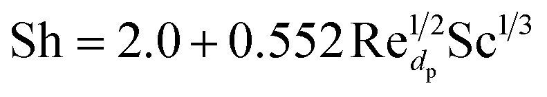
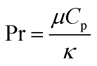
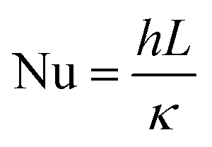
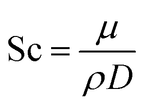
Transport analysis
Heat and mass transfer were analysed using dimensionless numbers Re, Sh and Nu to characterize the flow. These quantities were calculated using the averaged data from CFD simulations. Heat transfer from the wall was calculated using a constant temperature basis. The Fröessling correlation for mass transfer from the bulk flow to catalyst spheres was used (eqn (8)).43 On the other hand, Levenspiel and Walton correlation was applied for bed-wall heat transfer in fluidized systems (eqn (9)).44| |
 | (12) |
Results and discussion
Conversion and yield
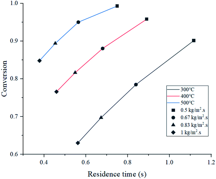
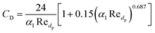
Simulated reactor showed an inverse relationship between conversion and feed mass flux (kg m−2 s−1), for the three temperatures in study as depicted in Fig. 5. It was found that operating at a slower flow rate resulted in better yields due to residence time. In all cases, higher temperatures improved conversion because of the endothermic chemistry of the process and the improved reaction rate (eqn (2)). Nevertheless, lower residence time values were reported at higher temperatures, as a result of thermal expansion, which increased gas velocity. A similar trend was observed in an experimental study by Mastral et al. where the influence of temperature and residence time was evaluated. Further discussion is regarding the mass and heat transfer effect of the experimental variables, previously mentioned on Re, Sh and Nu.45
 |
| | Fig. 5 Conversion and residence time at the operating conditions. | |
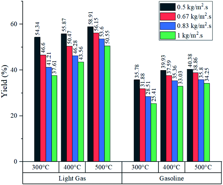
As shown in Fig. 6, both products (gasoline and light gases) yield shared a positive trend with respect to temperature and inverse with respect to feed mass flux. Light gas (C2–4) was produced in a higher rate in all cases as a result of the cracking reactions that convert both feed and gasoline into the lighter products. Elordi et al. observed a similar trend with a higher olefin abundance than the heavy paraffins.46 When the ratio of light gas to gasoline production was evaluated, it is revealed that 400 °C is the most favourable temperature for gasoline production, as seen in Table 4, because C5–11 formation reaction stands out. If temperature is lower (300 °C), reactions k1 to k4 from Table 2 predominate. Alternatively, at higher temperatures (500 °C), k5 and k7 cracking reactions are favored, thus, consuming gasoline, which is inconvenient, as this is the most valuable product. Considering the observations from Fig. 5, a high conversion was generally associated with a low feed flux. For optimization purposes, a trade-off between these variables was set to achieve the best results.
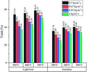 |
| | Fig. 6 Product yields at the operating conditions. | |
Table 4 L/G ratios at the operating conditionsa
| Temperature (°C) |
Feed mass flux (kg m−2 s−1) |
| 0.5 |
0.67 |
0.83 |
1 |
| L: light gas production rate (kg h−1). G: gasoline production rate (kg h−1). |
| 300 |
1.624 |
1.632 |
1.636 |
1.635 |
| 400 |
1.539 |
1.505 |
1.454 |
1.453 |
| 500 |
1.559 |
1.545 |
1.539 |
1.531 |
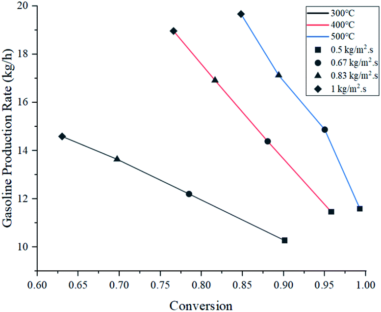
Fig. 7 shows gasoline production rates with respect to conversion at the assessed operating parameters. Operation at 400 °C showed very similar production rates to those at 500 °C, despite having lower conversion. As a partial conclusion, operating at 300 °C is highly discouraged due to its poor performance.
 |
| | Fig. 7 Gasoline production rate and conversion at the operating conditions. | |
When the feed flux was increased from 0.5 to 1 kg m−2 s−1 at 400 °C, conversion was compromised by 19.2% but overall production rate was improved by 65.4%. Similarly, at 500 °C, conversion dropped by 14.5% and production rate improved by 69.7%. This comparison shows that operating at 500 °C produces a smaller reduction in conversion and the best production rate improvement. However, these parameters do not guarantee selectivity towards gasoline. For this analysis, the ratio between the production rates of light gas and gasoline (L/G ratio) was reported in Table 4. Multiplying gasoline production rates from Fig. 7 with L/G yields numerical values for light gas production rate. From an operational standpoint, lower ratios are more convenient as they represent higher gasoline selectivity. For all feed fluxes, operation at 400 °C showed the lowest L/G values. No general trend was observed when evaluating different feed fluxes at a constant temperature. In the case of 300 °C, the ratio increased with the feed flux, while experiments at 400 and 500 °C reported the opposite effect. Operating at 1 kg m−2 s−1 and 400 °C showed the best L/G ratio for gasoline production.
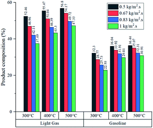
Fig. 8 shows the product composition in terms of mass from each experiment (it is assumed that the unreacted feed and inert gas fulfil the missing percentage). As expected from conversion data, higher temperatures reported an increased fraction of light gas and gasoline in all cases. Generally, at each feed flux, the variations in gasoline composition were wider from 300 to 400 °C in comparison with variations from 400 to 500 °C. Further analysis is developed in the section concerning heat transfer of this process to determine whether the improvement in production performance is worth the energy investment to raise the temperature from 400 to 500 °C.
 |
| | Fig. 8 Product compositions at the operating conditions. | |
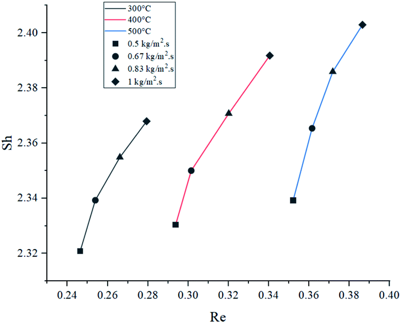
Mass transfer
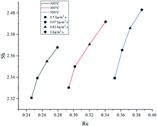
The relation between Sh and Re was plotted in Fig. 9. Results showed that higher feed rate increased Sh, meaning a slightly higher mass transfer by convection. Theoretically, mass transfer of the reactants from the bulk flow to the catalyst is expected to improve significantly by increasing the turbulence of the flow.47 Nevertheless, the magnitude of this effect is limited due to the size of the catalyst particles, which caused Re and Sh to take small values.
 |
| | Fig. 9 Effect of Re on Sh at the operating conditions. | |
At 500 °C, Sh increased by a poor 2.73% when comparing the highest and lowest feed rates, and it was the highest variation of the three temperatures. As temperature drove Re to different ranges in each set of experiments, it was observed that higher temperatures increased convective mass transfer by a small margin (1.45% being the greatest variation when comparing at 1 kg m−2 s−1), similarly to the effect of feed rate. These findings suggest that mass transfer rate between the catalyst and the bulk flow would be very similar under the tested condition range. In average, the values of Sc at 300 °C were 15.8% and 32.2% higher than those at 400 °C and 500 °C, respectively. However, as the graph shows, Sc had very little effect overall, due to its lower weight on eqn (12).
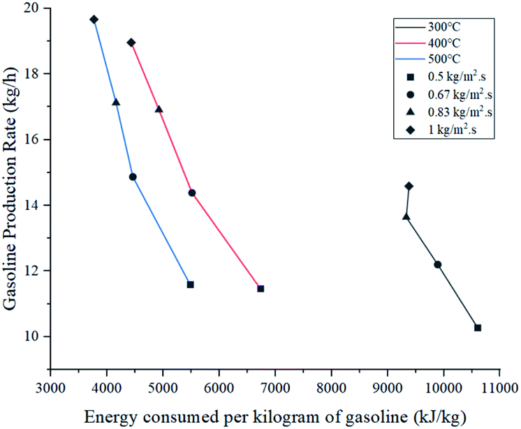
Heat transfer
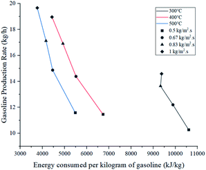
Energy consumed by the process was affected by temperature and feed mass flux. Since wall temperature had a constant value, lower inlet temperatures caused a higher gradient and thus, a higher energy transmission to the fluid in the form of sensible heat. For this reason, the energy used to heat up the mixture from 300 °C to each inlet temperature was considered in these calculations. Fig. 10 shows that the difference in energy consumption between 300 and 400 °C was far greater than between 400 and 500 °C. This coincides with the previous observation that increasing the temperature above 400 °C causes a less effective improvement. On the other hand, as energy consumption depends on the amount of feed reacting, higher feed fluxes distributed heat among a higher amount of mass, decreasing the energy consumed per kilogram of gasoline produced. As a preliminary conclusion, operating at 1 kg m−2 s−1 and 500 °C allowed the best gasoline production performance with the lowest energy consumption per unit of mass.
 |
| | Fig. 10 Energy consumption at the operating conditions. | |
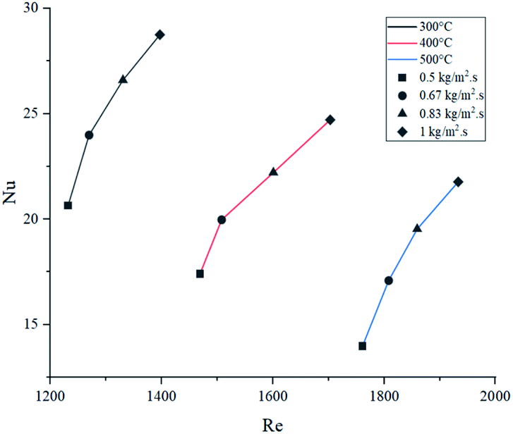
Fig. 11 presents the effect of Re on Nu. Higher temperatures showed lower Nu values, while higher feed fluxes showed increased values. These results agree with those presented by the literature, showing a direct relation of the convective heat transfer rate (Nu) with respect to flow velocity (Re).48,49 Naturally, temperature increased Re due to the previously discussed effect of thermal expansion. As each temperature presents significantly different densities, viscosities and velocities, they operate at different ranges of Re. However, Pr has a higher weight in eqn (13), hence the Re value from the higher temperatures was not sufficient to provide a better convective heat transfer.
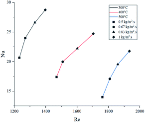 |
| | Fig. 11 Effect of Re on Nu at the operating conditions. | |
The values of μ, Cp and κ in this system showed a dynamic behaviour based on temperature and molecular weight MW, as shown in Table 5.
Table 5 Effect of temperature and MW on the thermal properties of gases50,51
| Thermal properties |
Effect of temperature |
Effect of molecular weight |
| μ |
Direct (↑) |
Direct (↑) |
| Cp |
Direct (↑) |
Direct (↑) |
| κ |
Direct (↑) |
Inverse (↓) |
Because of this behaviour, decomposition reactions had a crucial role in defining the thermal properties of the gas mixture. As lower temperatures are associated with lower conversion rates (heavier molecules are more abundant), μ and Cp were higher and κ was lower.50,51 Thus, the combined effect of these properties caused higher Nu values at lower temperatures. Even though operating at 1 kg m−2 s−1 and 400 °C provides a superior value for convection, overall energy efficiency at 500 °C produces lower operative costs (lower energy consumption per kilogram produced).
Transport analysis on the design
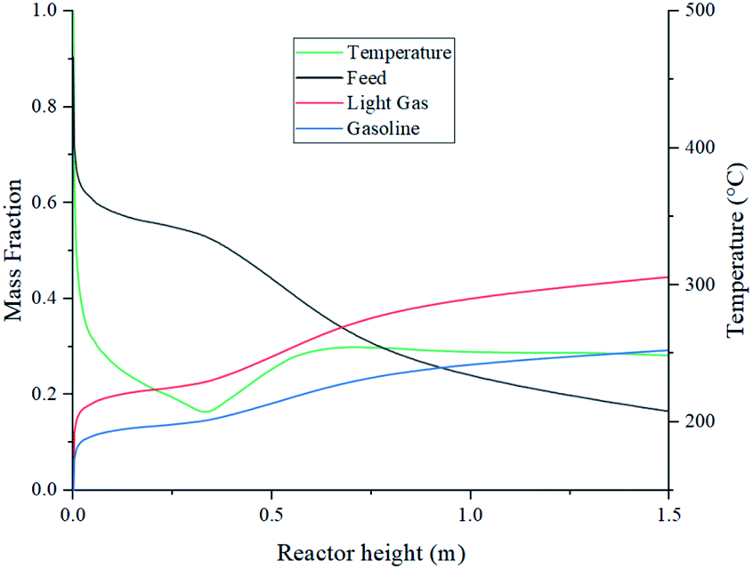
Further analysis at 1 kg m−2 s−1 and 500 °C design point was done to better understand the internal behaviour of the reactor using contour plots from CFD simulations. Fig. 12 shows mass fraction and gas temperature values vs. reactor height derived from the simulations. Regarding heat transfer, the temperature behaviour shows agreement with the results described by Hamzehei52 in which lower temperatures were reported at the densest region of the fluidized bed due to due to the highly endothermic chemistry of pyrolysis. Because of this, even though the inlet temperature is 500 °C, the reactor showed values as low as 205 °C in the inferior portion of the reactor, were most of the catalyst is present. At the upper region, with less catalyst concentration, temperature is slightly higher due to the lower reaction rate. As a result, the average outlet temperature was 250 °C.
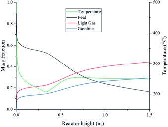 |
| | Fig. 12 Composition and temperature profiles vs. reactor height. | |
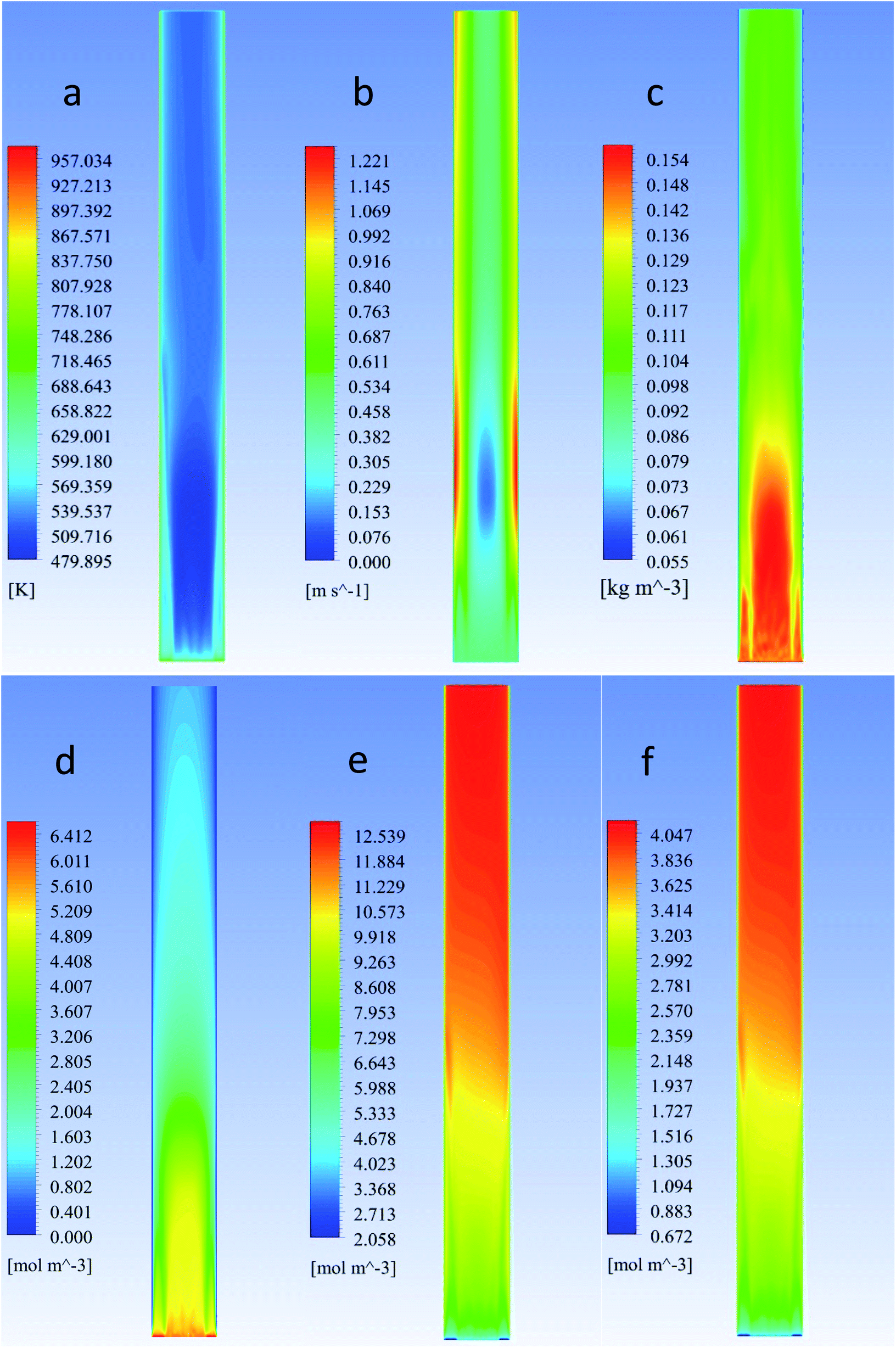
Fig. 13 depicts temperature, velocity and composition profiles with a higher fidelity. Fig. 13a shows the reactor temperature contour profile. Despite wall heating, results show a low temperature trend across the bed due to heat transfer from the gas to the catalyst particles.
 |
| | Fig. 13 (a) Temperature, (b) velocity and (c) catalyst mass concentration (d) feed, (e) light gas and (f) gasoline molar concentration contour profiles. | |
Fig. 13b, shows low net velocity magnitudes at the lower region of the reactor, that could be explained due to catalyst stagnation and local recirculation. Catalyst concentration profile can be observed in Fig. 13c and indicates an inverse relationship with respect to temperature, as gas density reduces with thermal expansion (eqn (3)). Local recirculation allows an appropriate residence time to the gas mixture (0.38 s estimated from Fig. 4). Thus, a high conversion rate is achieved at the lower region of the reactor.
Fig. 13d to f shows concentration profiles of feed and products at the selected conditions of this study, there is no a total conversion of the feed (Fig. 13d) and there is a desirable uniform distribution of the products (Fig. 13e and f).
Conclusions
The catalytic pyrolysis on a fluidized bed reactor shows great potential to enhance plastic waste processing. This study demonstrated the effects of temperature and feed rate on a fluidized bed reactor performance and its internal behaviour. From an operative standpoint, employing a feed flux of 1 kg m−2 s−1 at 500 °C showed the best gasoline production rate and the lowest energy consumption per kilogram of product. However, simulations at 400 °C showed a better trade-off between heat/mass transfer performance and also the best L/G ratio. The internal analysis of the reactor showed detailed information on process variables and reasonable agreement with literature, related to heat-transfer behaviour of gas–solid fluidized-bed reactors. Temperature and feed rate showed a very limited effect on convective mass transfer over the catalyst as demonstrated by the negligible variation of Sh.
Nomenclature
| U | Global heat transfer coefficient (J m−3 °C−1) |
| Tw | Wall temperature (°C) |
| Fi | Molar flow rate (mol s−1) |
| Cp,i | Specific heat of specie i (J kg−1 °C−1) |
| κ | Thermal conductivity (W m−1 K−1) |
| ρ | Density (kg m−3) |
| ρp | Particle density (kg m−3) |
| ρg | Gas density (kg m−3) |
| P | Pressure (Pa) |
| R | Universal gas constant (J mol−1 °C−1) |
| Vm | Molar specific volume |
| μ | Dynamic viscosity (kg m−1 s−1) |
| αq | Volume fraction of phase q |
| t | Time (s) |
 | Stress tensor (N m−2) |
![[v with combining right harpoon above (vector)]](https://www.rsc.org/images/entities/i_char_0076_20d1.gif) | Flow velocity (m s−1) |
![[q with combining right harpoon above (vector)]](https://www.rsc.org/images/entities/i_char_0071_20d1.gif) | Heat flux (W m−2) |
![[g with combining right harpoon above (vector)]](https://www.rsc.org/images/entities/i_char_0067_20d1.gif) | Gravity acceleration constant (m s−2) |
![[F with combining right harpoon above (vector)]](https://www.rsc.org/images/entities/i_char_0046_20d1.gif) | Force (N) |
| lift,s | Lift force on solid phase s (N) |
| vm,s | Virtual mass force on solid phase s (N) |
| Yi | Mass fraction of specie i |
![[J with combining right harpoon above (vector)]](https://www.rsc.org/images/entities/i_char_004a_20d1.gif) i i | Mass flux (kg m−2 s−1) |
| ṁ | Mass flow rate (kg s−1) |
| h | Specific enthalpy (J kg−1) |
| hpq | Interphase enthalpy between phases p and q (J kg−1) |
| ΔHr | Heat of reaction (W) |
| Qpq | Intensity of heat exchange between phases p and q (W) |
 | Reynolds number |
 | Prandtl number |
 | Nusselt number |
 | Schimdt number |
 | Sherwood number |
Author contributions
L. D. designed and conducted the experiments. U. R. provided supervision for the research activities. All authors analysed the data and wrote the paper.
Conflicts of interest
There are no conflicts to declare.
Acknowledgements
The authors thank the Universidad de Ingeniería y Tecnología for software license funding that made this research possible and professors Maribel Valverde PhD and Francisco Tarazona PhD for their support and advice.
References
- RPP Noticias, Perú solo recicla aún el 4 % de las 900.000 toneladas de plástico que desecha, https://rpp.pe/peru/actualidad/peru-solo-recicla-aun-el-4-de-las-900000-toneladas-de-plastico-que-desecha-noticia-1242755?ref=rpp, accessed 20 May 2021 Search PubMed.
- Ministerio del Ambiente, Cifras del mundo y el Perú, https://www.minam.gob.pe/menos-plastico-mas-vida/cifras-del-mundo-y-el-peru/, accessed 20 May 2021 Search PubMed.
- C. Ghenai, M. A. Rasheed, M. J. Alshamsi, M. A. Alkamali, F. F. Ahmad and A. Inayat, Case Stud. Therm. Eng., 2020, 22, 100773 CrossRef.
- D. Meier, B. Van De Beld, A. V. Bridgwater, D. C. Elliott, A. Oasmaa and F. Preto, Renewable Sustainable Energy Rev., 2013, 20, 619–641 CrossRef.
- M. Rehan, R. Miandad, M. A. Barakat, I. M. I. Ismail, T. Almeelbi, J. Gardy, A. Hassanpour, M. Z. Khan, A. Demirbas and A. S. Nizami, Int. Biodeterior. Biodegrad., 2017, 119, 162–175 CrossRef CAS.
- A. Lopez-Urionabarrenechea, I. De Marco, B. M. Caballero, M. F. Laresgoiti and A. Adrados, J. Anal. Appl. Pyrolysis, 2012, 96, 54–62 CrossRef CAS.
- I. Dubdub and M. Al-Yaari, Materials, 2020, 13, 1–15 CrossRef PubMed.
- M. Artetxe, G. Lopez, M. Amutio, J. Bilbao and M. Olazar, Chem. Eng. Sci., 2014, 116, 635–644 CrossRef CAS.
- S. Khedri, Kinetic and thermodynamic studies on pyrolysis of waste HDPE polymers, Lakehead University, 2017, https://knowledgecommons.lakeheadu.ca/handle/2453/4247 Search PubMed.
- D. K. Ratnasari, M. A. Nahil and P. T. Williams, J. Anal. Appl. Pyrolysis, 2017, 124, 631–637 CrossRef CAS.
- D. P. Serrano, J. Aguado and J. M. Escola, ACS Catal., 2012, 2, 1924–1941 CrossRef CAS.
- R. Miandad, M. A. Barakat, A. S. Aburiazaiza, M. Rehan and A. S. Nizami, Process Saf. Environ. Prot., 2016, 102, 822–838 CrossRef CAS.
- T. Chen, X. Ku, J. Lin and H. Ström, Energies, 2020, 13(20), 5358 CrossRef CAS.
- S. Hafeez, E. Aristodemou, G. Manos, S. M. Al-Salem and A. Constantinou, React. Chem. Eng., 2020, 5, 1083–1092 RSC.
- L. J. Yin, D. Z. Chen, H. Wang, X. B. Ma and G. M. Zhou, Chem. Eng. J., 2014, 237, 229–235 CrossRef CAS.
- M. Andersen, K. A. Sætre, S. Fredriksen and C. Pfeiffer, in, Proceedings of The 59th Conference on Simulation and Modelling (SIMS 59) 26-28 September 2018, Oslo Metropolitan University, Norway, 2018, vol. 153, pp. 303–307 Search PubMed.
- S. Mazloum, S. Awad, N. Allam, Y. Aboumsallem, K. Loubar and M. Tazerout, Appl. Energy, 2021, 283, 116375 CrossRef CAS.
- D. P. Patel and P. S. Patelb, Int. Res. J. Eng. Technol., 2019, 679–687 Search PubMed.
- E. Hartulistiyoso, F. A. P. A. G. Sigiro and M. Yulianto, Procedia Environ. Sci., 2015, 28, 234–241 CrossRef CAS.
- K. Ding, Q. Xiong, Z. Zhong, D. Zhong and Y. Zhang, Powder Technol., 2020, 362, 177–187 CrossRef CAS.
- W. Shen, Wuli Huaxue Xuebao, 2017, 33, 2321–2322 CAS.
- Q. Xue, D. Dalluge, T. J. Heindel, R. O. Fox and R. C. Brown, Fuel, 2012, 97, 757–769 CrossRef CAS.
- A. Gala, D. Catalán-Martínez, M. Guerrero and J. M. Serra, Fuel, 2021, 287, 119400 CrossRef CAS.
- M. S. Qureshi, A. Oasmaa, H. Pihkola, I. Deviatkin, A. Tenhunen, J. Mannila, H. Minkkinen, M. Pohjakallio and J. Laine-Ylijoki, J. Anal. Appl. Pyrolysis, 2020, 152, 104804 CrossRef CAS.
- R. Miandad, M. Rehan, M. A. Barakat, A. S. Aburiazaiza, H. Khan, I. M. I. Ismail, J. Dhavamani, J. Gardy, A. Hassanpour and A.-S. Nizami, Front. Energy Res., 2019, 7, 92–108 CrossRef.
- G. Towler and R. Sinnott, Chemical Engineering Design, Elsevier, Oxford, 6th edn, 2020 Search PubMed.
- J. A. Mendoza and S. Hwang, Korean J. Chem. Eng., 2018, 35, 2157–2163 CrossRef CAS.
- J. A. Federici and D. G. Vlachos, Combust. Flame, 2008, 153, 258–269 CrossRef CAS.
- E. V. Rebrov, J. C. Schouten and M. H. J. M. de Croon, Chem. Eng. Sci., 2011, 66, 1374–1393 CrossRef CAS.
- A. López, I. de Marco, B. M. Caballero, M. F. Laresgoiti and A. Adrados, Chem. Eng. J., 2011, 173, 62–71 CrossRef.
- J. Srinakruang, Process for producing fuel from plastic waste material by using dolomite catalyst, US8344195, 2013, https://patents.google.com/patent/US8344195?oq=US8344195.
- S. Jeol, System and process for converting plastics to petroleum products, US2015001061, 2015, https://patents.google.com/patent/US20150001061A1/en.
- M. Sarker, Method for converting waste plastic to lower-molecular weight hydrocarbons, particularly hydrocarbon fuel materials, and the hydrocarbon material produced thereby, US8927797, 2015, https://patents.google.com/patent/US8927797B2/en.
- T. M. Knowlton, Fluidized bed reactor design and scale-up, Woodhead Publishing Limited, 2013 Search PubMed.
- J. G. Yates and P. Lettieri, Fluidized-Bed Reactors: Processes and Operating Conditions, 2016, vol. 26 Search PubMed.
- R. Cocco, S. B. R. Karri and T. Knowlton, Chem. Eng. Prog., 2014, 110, 21–29 Search PubMed.
- ACS Material, ZSM-5 Series Zeolite (MFI) Powder, https://www.acsmaterial.com/zsm-5-series-zeolite-powder.html, accessed 6 May 2021 Search PubMed.
- A. Griesinger, K. Spindler and E. Hahne, Int. J. Heat Mass Transfer, 1999, 42, 4363–4374 CrossRef CAS.
- L. Qiu, V. Murashov and M. A. White, Solid State Sci., 2000, 2, 841–846 CrossRef CAS.
- J. Seader, E. Henley and K. Roper, Separation Process Principles, Wiley, Hoboken, 3rd edn, 2011 Search PubMed.
- Crane Co., Flow of Fluids Through Valves, Fittings & Pipe, Stamford, 2013 Search PubMed.
- ANSYS Inc., ANSYS FLUENT 18.1 Theory Guide, 2017 Search PubMed.
- H. S. Fogler, Elements of Chemical Reaction Rngineering, Prentice Hall, Philadelphia, PA, 5th edn, 2016 Search PubMed.
- K. M. Wagialla, S. S. Elnashaie and A. H. Fakeeha, J. King Saud Univ., Eng. Sci., 1990, 2, 331–345 CAS.
- F. J. Mastral, E. Esperanza, P. García and M. Juste, J. Anal. Appl. Pyrolysis, 2002, 63, 1–15 CrossRef CAS.
- G. Elordi, M. Olazar, P. Castaño, M. Artetxe and J. Bilbao, Ind. Eng. Chem. Res., 2012, 51, 14008–14017 CrossRef CAS.
- C. J. Geankoplis, A. A. Hersel and D. H. Lepek, Transport Processes and Separation Process Principles, Prentice Hall, 5th edn, 2018 Search PubMed.
- O. Molerus and K.-E. Wirth, Heat Transfer in Fluidized Beds, Springer Netherlands, 1997 Search PubMed.
- W. M. Rohsenow, J. P. Hartnett and Y. I. Cho, Handbook of Heat Transfer, McGraw-Hill, 3rd edn, 1998 Search PubMed.
- P. Edward, T. O. Id, P. G. Brewer and E. T. Peltzer, Geophys. Res. Lett., 2019, 46, 0–3 Search PubMed.
- I. E. Maloka, E. T. Hashim and S. Y. Ibrahim, Pet. Sci. Technol., 2007, 37–41 Search PubMed.
- M. Hamzehei and H. Rahimzadeh, Ind. Eng. Chem. Res., 2009, 3177–3186 CrossRef CAS.
|
| This journal is © The Royal Society of Chemistry 2022 |
Click here to see how this site uses Cookies. View our privacy policy here. 
 Open Access Article
 This Open Access Article is licensed under a Creative Commons Attribution-Non Commercial 3.0 Unported Licence
 * and
Ursula Fabiola Rodríguez-Zúñiga
* and
Ursula Fabiola Rodríguez-Zúñiga