
 Open Access Article
 This Open Access Article is licensed under a Creative Commons Attribution-Non Commercial 3.0 Unported Licence
Effects of liquid crystal polymer (LCP) on the structure and performance of PEEK/CF composites†
Meiyun Song ,
Xiaoqing Wang*,
Ran Du,
Zhen Zhou,
Xiaomeng Li,
Guoping Li and
Yunjun Luo
,
Xiaoqing Wang*,
Ran Du,
Zhen Zhou,
Xiaomeng Li,
Guoping Li and
Yunjun Luo
School of Materials Science and Engineering, Beijing Institute of Technology, Beijing, 100081, China. E-mail: wangxq@bit.edu.cn
First published on 25th April 2022
Abstract
Carbon fiber reinforced polyether ether ketone (PEEK/CF) composites feature diverse advantages and have been applied in various fields. However, the high melt viscosity of PEEK leads to their poor processing performance and affects their practical applications. Here a liquid crystal polymer (LCP) was introduced into a PEEK/CF system as a new strategy to address the aforementioned issues. Bearing aromatic rings on the main chains, LCP can strongly interact with PEEK by pi–pi interaction, which alters the crystallization behaviour and facilitates processing of PEEK/CF, eventually improving its mechanical performance. As a result, a high crystallinity (37.37%), a decreased equilibrium torque (8.902 Nm), and a high tensile strength (230.97 MPa) are realized with 5 wt% LCP. The current approach offers a new solution to simultaneously promote processing and mechanical performance of PEEK/CF and other polymer-based composites.
1 Introduction
Carbon fiber reinforced polyether ether ketone (PEEK/CF) composites feature high strength, low density, good friction resistance, high thermal stability, high flame retardant, good biocompatibility and so on,1,2 which facilitate their use in aerospace, automobile manufacturing, medical and other fields.3–8 However, the rigid chains and strong intermolecular interactions resulting from the benzene groups on the main chain of PEEK highly retard the movement of its chain segments, leading to its high melting point, high viscosity and poor processability. This issue inevitably leads to the uneven distribution of CFs in the PEEK matrix and thus the deteriorated mechanical performance. Inefficient control of the crystallization behaviour is another problem encountered using a PEEK matrix, which may reduce the stability of PEEK during processing9 and thereby affect the performance of the resulting composites. Additionally, the physical and mechanical performance of PEEK/CF is also closely associated with the crystallinity of PEEK.10,11 Therefore, it is essential to seek for effective ways to manipulate the fluidity and crystallization behaviours of PEEK matrix, thus facilitating processing and optimizing the mechanical performance (e.g., tensile strength) of PEEK/CF.Researchers usually focused on the interface modification of PEEK/CF composite to improve the interface interaction of PEEK and CF, such as by oxidation modification,12,13 graft modification,14,15 plasma modification16,17 and sizing treatment modification.18,19 For example, –NH2 was grafted onto activated CF to prepare PEEK/CF composite,20 whose interlaminar shear strength (ILSS) was increased by 33.4% (from 48 MPa to 64 MPa). However, the high temperature performance of the composite was limited owing to the high-temperature-sensitive amino groups. Additionally, the pre-treatment of CF, such as by oxidation, can also damage the strength of PEEK/CF to some extent. In another study,21 coating CF with polyimide and CNT increased the flexural strength of CF/PEEK by 63%. However, the crystallization and processing performance have not been studied.
Previous attempts were made to improve the processing performance of PEEK by chemical modification22,23 and blending with other polymers (such as polyethersulfone),24 but both of them reduced the mechanical performance of PEEK. Thermotropic liquid crystal polymer (LCP) resin features good fluidity and excellent mechanical performance,25 stands out among a wide range of engineering polymers.26 Particularly, during the process of melt extrusion, molecular chains of LCP tend to orientate and form microfiber structure, which can facilitate processing.27–34 What's more, the addition of LCP can also improve the degree of crystallinity of polymer and thus improve the mechanical performance, which is widely used as additive in many polymer systems. Blending LCP (Vectra B950) with PA46 led to a decrease of the viscosity compared to that of each component,35 and the tensile strength of the blend was found to be positively correlated to the amount of LCP. Mixing LCP36 with PA1010 and PP promoted the crystallization process and considerably improved the tensile strength as a result.37 Moreover, bearing with aromatic rings on the main chain, LCP can strongly interact with PEEK by pi–pi interaction and can be processed at high temperature,38 thus displaying considerable potential to modulate diverse performance of PEEK. The early studies found that undesirable properties, such as the impeded crystallization behavior,38–40 were obtained with the PEEK/LCP composites. However, the results were somehow misleading because of the excessive amount of LCP was applied. Hence, it is necessary to revisit the function of LCP by subtly design, so as to boosting the performance of PEEK/CF.
In this regard here, LCP41 with main chain consisting of 4-hydroxy benzoic acid and hydroxy naphthoic acid was introduced to modulate the crystallization behaviour and processing/mechanical performance of PEEK/CF without reducing the intrinsic mechanical performance of CF (Fig. 1). The amount of LCP was carefully designed, so as to balance the two effects of LCP, i.e., as the nucleating agent to promote crystallization and as an exotic component to cause the unfavourable phase separation. In this light the resulting PEEK/CF displayed enhanced crystallization behavior, processing and mechanical performance without compromising the thermal stability. The current study offers a new way to improve processing and mechanical performance of PEEK/CF composites for practical applications.
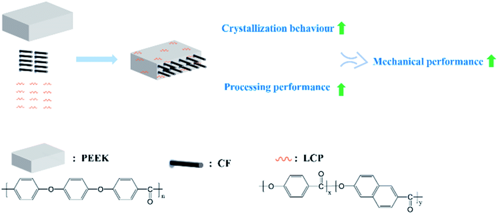 | ||
| Fig. 1 Schematic illustration of fabrication of PEEK/CF with LCP for enhanced mechanical performance (the percentage of CF was fixed at 30 wt%, PEEK/CF composites with different LCP contents were expressed as PEEK/CF/LCP-x%, x = 0, 3, 5, 7.). | ||
2 Experimental section
2.1 Materials
PEEK resin (VESTAKEEP® 2000G, with a density of 1.3 g cm−3, a melt flow rate of 70 g/10 min under the condition of 380 °C/5 kg, a mold shrinkage of 1.1%, and a vicat softening temperature of 335 °C) was purchased from Evonik Industrial Group (China). CF (T700, 2 mm length, 5 μm diameter) was purchased from China. LCP (Vectra® A950, with a density of 1.4 g cm−3, a lateral flow shrinkage rate of 0.70%, a melting temperature of 280 °C) was purchased from Celanese Corporation (America).2.2 Fabrication of PEEK/CF/LCP
PEEK, CF and LCP were mixed in an internal mixer (Brabender Gmbh & Co. KG, Germany) at 380 °C for 7 minutes according to the designed formula. For the mechanical performance characterizations, the as-prepared composites were injected by an injection molding machine, and dumbbell-shaped splines were prepared according to the GB-T 1040.2-2006.2.3 Characterization
X-ray diffraction (XRD) test: Model was X' Pert PRO MPD, Panalytical Company, Netherlands, test Conditions 2θ = 10–40°, the scan speed was 4° min−1, the test temperature was 25 °C, the electrode material was Cu target, the tube pressure was 40 kV, and the tube flow was 40 mA, measuring corner radius 240.00 nm. Differential scanning calorimeter (DSC) was performed on a DSC1/500/578 Differential Scanning Calorimeter (Mettler-Toledo Company, Switzerland) under N2 protection at the flow rate of 40 mL min−1. Internal mixing was performed on a Brabender mixer and the test temperature was 380 °C. Injection molding was performed on a MiniJet II, HAAKE Company, Germany, and the injection temperature was 385 °C, the injection pressure was 50 MPa, and the mold temperature was 250 °C. Tensile test was performed on a Instron 26022, Shimadzu Company, Japan, and the test temperature was 25 °C, and the tensile rate was 2 mm min−1. Scanning electron microscopy (SEM): A Hitachi S4800, before analysis, the surfaces were coated with thin layers of gold of about 100 Å. Thermogravimetry (TG) was performed on a DSC/TGA1, Mettler-Toledo Company, Switzerland, and the heating rate was 10 °C min−1, the N2 atmosphere was 20 mL min−1, and the test temperature was from 30 °C to 900 °C.3 Results and discussion
3.1 Crystallization behavior
The XRD curves of LCP, PEEK raw materials and the composites of PEEK/CF with the mass present of 0, 3, 5, 7% LCP are shown in Fig. 2. The 2θ angle of PEEK Bragg diffraction peaks are 29.07°, 22.95°, 21.03° and 19.02°, which refer to (211), (200), (111) and (110) crystal planes of the normal rhombic cell of polymer matrix, respectively.42 The characteristic peak of LCP is observed at 20.35°, thus there is a relatively small peak at 20.35° in PEEK/CF/3% LCP. While in PEEK/CF/5% LCP and PEEK/CF/7% LCP, this small peak gradually joins up with the one (21.03°) behind it. However, due to the low content of LCP, there is not much of change in the phases of PEEK. In addition, compared with PEEK, the peak appearing between 24° and 28° in PEEK/CF and PEEK/CF/LCP is attributed to (002) crystal plane of CF.43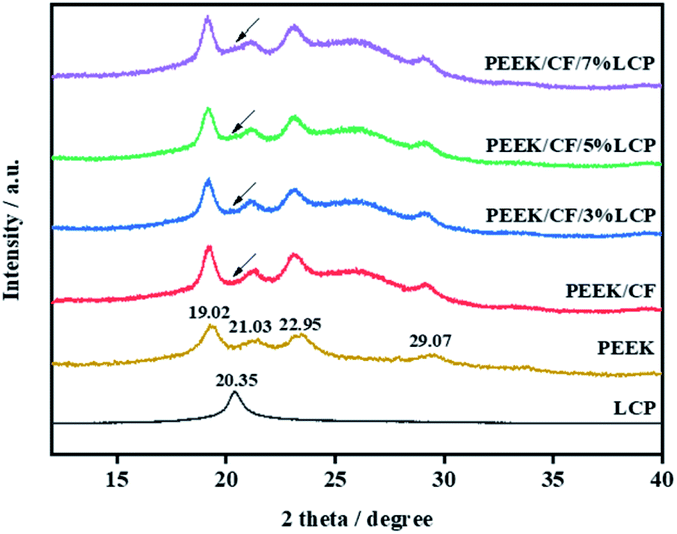 | ||
| Fig. 2 XRD curves of LCP, PEEK and PEEK/CF with different LCP contents (0, 3%, 5%, 7%). | ||
Crystallization kinetics, as a method to study the crystallization properties of polymers, can be divided into isothermal crystallization and non-isothermal crystallization. The molding processes of polymer are often carried out under dynamic and non-isothermal conditions, so the study of non-isothermal crystallization kinetics is more suitable for production practice and facilitate investigation of the processing conditions and product quality. Bearing aromatic rings on the main chains, LCP can strongly interact with PEEK by pi–pi interaction, which alters the crystallization behaviour. Therefore, here the effects of LCP on non-isothermal crystallization properties of PEEK/CF composites were studied.
The non-isothermal crystallization kinetics of PEEK/CF composites with different content of LCP were studied by DSC technique. The DSC thermograms of non-isothermal crystallization for these PEEK/CF/LCP composites at different cooling rates are presented in Fig. 3, from which parameters such as peak crystallization temperature (Tp), initial crystallization temperature (T0) and crystallization temperature range (D) were obtained as shown in Table S1.† With increasing cooling rate, T0 and Tp shifted to lower temperature. Besides, with the addition of LCP, all composites displayed lower T0 and Tp. Taking 10 K min−1 as an example, T0 and Tp display the minimum values (306.45 °C and 298.38 °C) at 5% LCP during the investigated LCP range (3–7%). Similar phenomena were also observed for other cooling rates, suggesting that PEEK/CF composite with 5% LCP features the lowest crystallization temperature.
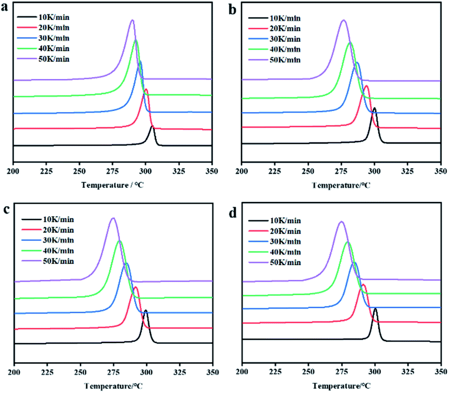 | ||
| Fig. 3 DSC thermograms of non-isothermal crystallization at different cooling rates for PEEK/CF composites with different LCP contents (a) 0% (b) 3% (c) 5% and (d) 7%. | ||
Relative crystallinity Xt is usually characterized by the integral area of the heat flow curve of crystallization peak over temperature and time. Fig. 4 presents the amorphous fraction (1 − Xt) of PEEK/CF/LCP as a function of temperature and time, respectively, suggesting that the delayed effect of the cooling rate on crystallization of PEEK/CF. The values of crystallization half-life (t1/2) were determined from Fig. 4 and summarized in Table S1,† which can reflect the crystallization rate of the polymer. It can be seen that t1/2 decreases with increasing cooling rate. What's more, with the addition of LCP, t1/2 was shortened and reach the minimum value for PEEK/CF/LCP-5%. Taking 10 K min−1 as an example, the composite displayed the fastest crystallization rate (a shortest t1/2 of 0.77 min) with 5% LCP.
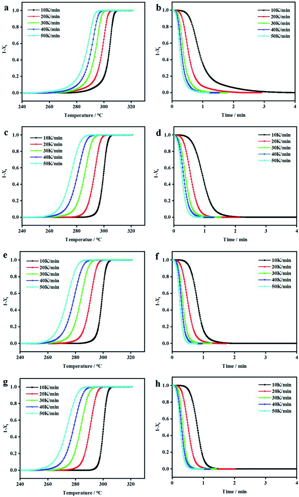 | ||
| Fig. 4 Plots of amorphous fraction as a function of temperature and time for PEEK/CF composites with different LCP contents: (a) and (b) 0%, (c) and (d) 3%, (e) and (f) 5% and (g) and (h) 7% crystallized non-isothermally at various cooling rates. | ||
Besides t1/2, the crystallization behavior can also be described as follows,44
log![[thin space (1/6-em)]](https://www.rsc.org/images/entities/char_2009.gif) φ = F(T) − αlogt φ = F(T) − αlogt |
φ against logt. The physical significance of the rate parameter F(T) refers to the necessary cooling rate to achieve the specified crystallinity at unit crystallization time, which represents the speed of the crystallization rate of the polymer. The larger F(T) is, the lower the crystallization rate of the whole system.
Fig. 5 shows the function diagram of logφ and logt of PEEK/CF/LCP composites. According to the slope and intercept of fitting, α and F(T) of samples can be obtained and are shown in Table S2.† Compared with PEEK/CF, the parameter α remains roughly unchanged while the fitting intercept is considerably altered with the addition of LCP. Taking 10 K min−1 as an example, F(T) for all the samples decreased after the addition of LCP and a minimum F(T) of 3.63 was derived for PEEK/CF/LCP-5%. The same trend applied for other cooling rates, indicating the profound effect of LCP, particularly with 5% amount, for promoting the crystallization process. The above results show that crystallization rate reaches the maximum at a medium amount of LCP (5%), which can be rationalized by dual effects imposed by LCP. On the one hand, the added LCP can function as nucleation agent and promote the crystallization. On the other hand, too much LCP may destroy the regularity of PEEK/CF and hinder the movement of PEEK chain segment. As a result, the fastest crystallization rate is achieved with 5% LCP.
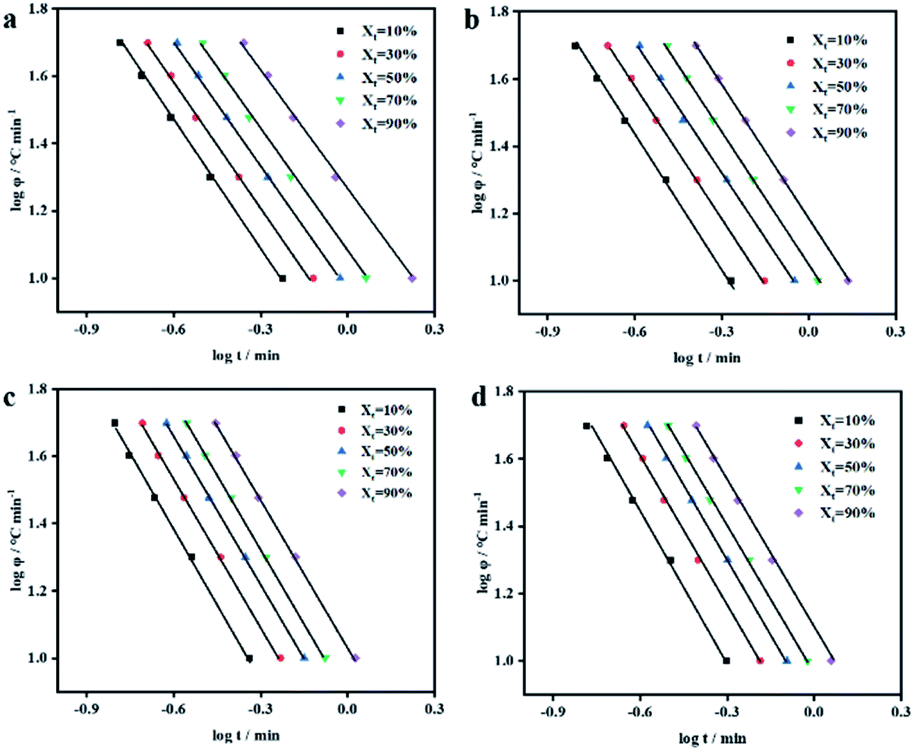 | ||
| Fig. 5 Plots of logφ as a function of logt for PEEK/CF composites with different LCP contents (a) 0% (b) 3% (c) 5% and (d) 7%. | ||
On the other hand, the addition of LCP also affects the crystallinity and its calculation formula is as follows:
| Xc = ΔH/(ΔH0 × Wf) |
| PEEK/CF | PEEK/CF/3% LCP | PEEK/CF/5% LCP | PEEK/CF/7% LCP | |
|---|---|---|---|---|
| ΔH/(J g−1) | 30.40 | 31.04 | 32.31 | 28.93 |
| Crystallinity (%) | 33.41 | 35.16 | 37.37 | 34.18 |
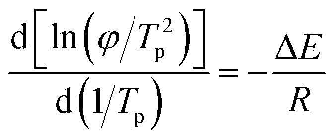
The kinetic activation energy of non-isothermal crystallization can be used to characterize how easily polymer crystals grow. The lower the activation energy, the easier the crystal grows. Table 2 shows the influence of different contents of LCP on the activation energy of PEEK/CF composites calculated by Kissinger's equation as follows:
| PEEK/CF | PEEK/CF/3% LCP | PEEK/CF/5% LCP | PEEK/CF/7% LCP | |
|---|---|---|---|---|
| ΔE/kJ mol−1 | 236.35 | 143.06 | 133.52 | 162.47 |
Fig. 6 is the fitting line and Table 2 shows that the activation energy of the composite decreases greatly after the addition of LCP, expressing a trend of decreasing first and then increasing with the increase of LCP content. When the content of LCP is 5%, the activation energy of PEEK/CF/LCP is the lowest at 133.52 kJ mol−1, and is 43.51% less than PEEK/CF, which also indicates that LCP can promote the crystallization of PEEK/CF composites.
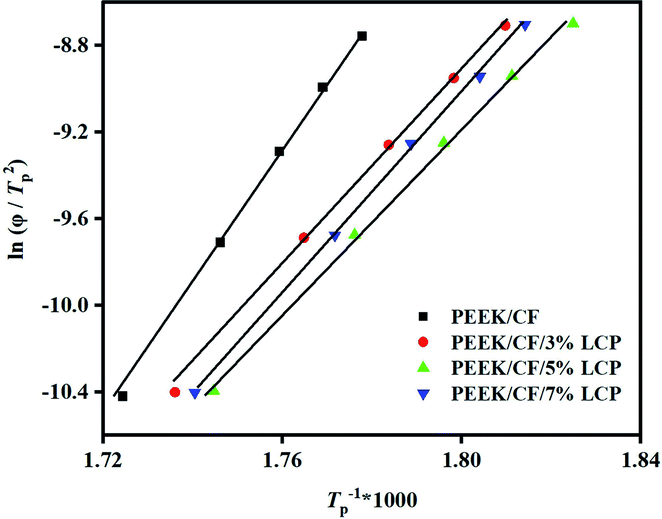 | ||
Fig. 6 Plots of  as a function of 1/Tp × 1000 for PEEK/CF composites with different LCP contents. as a function of 1/Tp × 1000 for PEEK/CF composites with different LCP contents. | ||
3.2 Processing performance
In order to study the influence of LCP on the processing performance of PEEK/CF composites, we used the torque curve of the mixer and SEM to analyze the processability performance of PEEK/CF composites with different contents of LCP.Fig. 7 shows the torque temperature curve of PEEK/CF composites with different contents of LCP. When the feeding is completed, the torques of different composites eventually tend to converge to a finite value, and the processability performance can be evaluated by using the equilibrium torque.
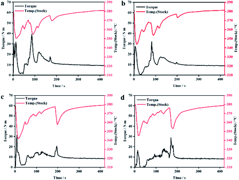 | ||
| Fig. 7 Torque–temperature–time curve of PEEK/CF composites with different LCP contents (a) 0% (b) 3% (c) 5% and (d) 7%. | ||
From Fig. 8, it is clear that the increase of LCP content decreases the equilibrium torques of composites, indicating lower melt viscosity and better fluidity at a higher amount of LCP.
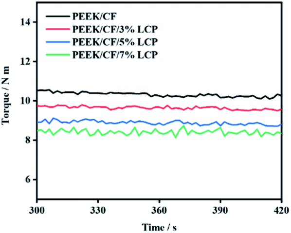 | ||
| Fig. 8 Torque–temperature–time curve of PEEK/CF composites with different LCP contents at 300 s to 420 s. | ||
From Table 3, the lowest equilibrium torque was 8.588 Nm with 7% LCP, which is 18.17% lower compared to that of PEEK/CF. This is because that the melt viscosity of LCP was very low after melting. Hence, it could act as a “plasticizer” to reduce the melt viscosity of the blend system.31 At the same time, LCP was prone to orientation during processing.27–31 The rigid rod-like LCP molecules with orientation can function as lubricants, which reduced the entanglement of thermoplastic molecular chains, thus reducing the melt viscosity of the blend and making it easier to process. Therefore, adding LCP can improve the processing performance of PEEK/CF composites.
| Equilibrium torque/Nm | Rate of reduction/% | |
|---|---|---|
| PEEK/CF | 10.495 | — |
| PEEK/CF/3% LCP | 9.850 | 6.15% |
| PEEK/CF/5% LCP | 8.902 | 15.18% |
| PEEK/CF/7% LCP | 8.588 | 18.17% |
The results of processing performance of PEEK/CF composites in which the distribution of carbon fibers in the fracture surface are revealed by SEM imaging. In Fig. 9, with the increase of LCP content, the distribution of carbon fiber in the matrix becomes more and more uniform. This indicates that the addition of LCP improves the fluidity of PEEK/CF composites, and the higher the LCP content, the better the fluidity, and the more uniform the distribution of carbon fibers. Therefore, the improved processing performance have been further confirmed. After the addition of LCP, PEEK/CF composites are changed from brittle fracture to ductile fracture, although CF pullout can be found to increase with the increase in LCP content. This is owing to the improvement of the interface bonding between PEEK and CF, which is consistent with the enhancement of mechanical property of PEEK/CF/LCP composites.
 | ||
| Fig. 9 SEM for PEEK/CF composites with different LCP contents (a) 0% (b) 3% (c) 5% and (d) 7%. | ||
3.3 Tensile performance
The mechanical performance of PEEK/CF can be further controlled by adding LCP to regulate the influence of crystallization behavior/treatment performance. In order to investigate the effects of adding LCP on the mechanical performance of PEEK/CF, the tensile performance of the samples were tested.It can be seen from Fig. 10 and Table 4 that with the increase of LCP content, the maximum tensile strength and strain of PEEK/CF composites increased first and then decreased together, and they are both higher than that of composites without LCP. Besides, the addition of LCP has little effect on the elastic modulus of PEEK/CF/LCP composites.
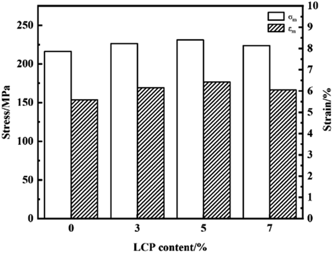 | ||
| Fig. 10 Bar charts of tensile performance PEEK/CF composites with different LCP contents. | ||
| σm/MPa | εm/% | Elastic modulus/MPa | |
|---|---|---|---|
| PEEK/CF | 216.27 | 5.59 | 5833.40 |
| PEEK/CF/3% LCP | 226.35 | 6.16 | 5804.03 |
| PEEK/CF/5% LCP | 230.97 | 6.42 | 5843.49 |
| PEEK/CF/7% LCP | 223.65 | 6.09 | 5879.58 |
When LCP content is 5% in PEEK/CF/LCP, the maximum tensile strength and strain of the composite reach 230.97Mpa and 6.42%, which increase by 6.80% and 14.85%, respectively, compared with PEEK/CF. The improvement of mechanical performance may be due to the synergistic effect of enhanced crystallization and processing performance. On the one hand, the addition of LCP alters the crystallization property, thus enhancing the tensile performance. On the other hand, the orientation of LCP after mixing with PEEK/CF improves the processing fluidity and thereby boosts the mechanical performance of composites. In addition, the orientation structure formed by spontaneous orientation after LCP melting can be developed into microfibers under tensile conditions, which can improve the physical performance of blends to a certain extent. However, the tensile strength decreased to some extent with 7% LCP due to the reason that excessive LCP may destroy the regularity of PEEK/CF and hinder the movement of PEEK chain segment, which is consistent with the conclusion of crystallization behaviour.
3.4 Thermal stability
Because thermal performance is one of the important properties of composites, the thermal stability of PEEK/CF/LCP was also studied. Fig. 11 shows the TG and DTG curves of LCP, PEEK and PEEK/CF composites after adding different contents of LCP (the data are listed in Table S3†). Compared with PEEK and LCP, the thermal degradation rate of PEEK/CF/LCP is retarded due to the excellent thermal stability of CF. The initial thermal decomposition temperature (T5%) of LCP is 490.8 °C, which is 81.98 °C lower than that of PEEK, thus the introduction of LCP has reduced the thermal stability of PEEK/CF/LCP to a small extent. Besides, the addition of LCP has also slowed the thermal decomposition rate of PEEK/CF/LCP marginally.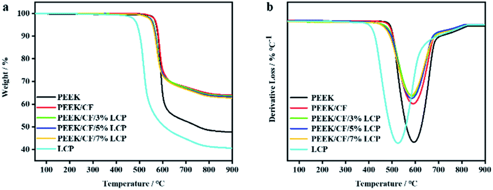 | ||
| Fig. 11 (a) TG and (b) DTG of LCP, PEEK, and PEEK/CF composites with different LCP contents. | ||
4 Conclusions
In summary, LCP (Vectra® A950), bearing with aromatic groups on its main chain, is introduced into the PEEK/CF system to alter its crystallization behavior and processing performance, so as to enhance the mechanical properties such as the tensile strength. By balancing the two effects of LCP, i.e., as the nucleating agent to promote crystallization and as an exotic component to cause the unfavorable phase separation, an optimized amount of LCP (5%) was found to improve diverse performance of the composites, where a high crystallinity (37.37%) and a low equilibrium torque (8.902 Nm, ∼15.18% lower than that of bare PEEK/CF) are obtained. In this light, the improvement of crystallization and processing performance contribute to a high tensile strength of 230.97 MPa. The presented strategy offers a new way to considerably facilitate processing and enhance mechanical performance of PEEK-based composites, which may also be applied to broad high-melting-point composite systems for the performance enhancement.Conflicts of interest
The authors declare that they have no known competing financial interests or personal relationships that could have appeared to influence the work reported in this paper.Notes and references
- K. Senthilnathan, C. P. Hiremath, N. K. Naik, A. Guha and A. Tewari, Composites, Part A, 2017, 100, 118 CrossRef CAS.
- V. Kostopoulos, A. Kotrotsos, S. Tsantzalis, P. Tsokanas, T. Loutas and A. W. Bosman, Compos. Sci. Technol., 2016, 128, 84 CrossRef CAS.
- Z. Zhang, Mphil thesis, Donghua University, 2017.
- H. Li, Mphil thesis, Tianjin University, 2006.
- X. X. Wu, Mphil thesis, Nanjing University of Science and Technology, 2012.
- X. P. Yang, Synth. Fiber, 2021, 50, 41 Search PubMed.
- S. W. Ha, J. Mayer, B. Koch and E. Wintermantel, J. Mater. Sci.: Mater. Med., 1994, 5, 6 CrossRef.
- H. l. Luo, G. Y. Xiong, Z. W. Yang, R. S. Raman, Q. P. Li, C. Y. Ma, D. Y. Li, Z. R. Wang and Y. Z. Wan, J. Mech. Behav. Biomed. Mater., 2014, 29, 103 CrossRef CAS PubMed.
- M. Regis, A. Bellare, T. Pascolini and P. Bracco, Polym. Degrad. Stab., 2017, 136, 121 CrossRef CAS.
- M. Sattari, A. Molazemhosseini, M. R. Naimi-Jamal and A. Khavandi, Mater. Chem. Phys., 2014, 147, 942 CrossRef CAS.
- H. Sun, X. Yang, K. Wei, Y. Wu and W. Fang, J. Therm. Anal. Calorim., 2019, 138, 369 CrossRef CAS.
- T. Wang, Y. S. Jiao, Z. M. Mi, J. T. Li and D. M. Wang, High Perform. Polym., 2019, 32, 383 CrossRef.
- W. X. Shen, Y. L. Jiang and A. P. Zhu, J. Compos. Mater., 2021, 38, 1809 Search PubMed.
- W. Qin, Y. Li, J. Ma, Q. Liang and B. Tang, J. Mech. Behav. Biomed. Mater., 2019, 89, 227 CrossRef CAS PubMed.
- H. Jia, X. H. Cui, X. Q. Liu, Y. Li, W. Qin and J. Ma, Plast. Ind., 2019, 47, 55 Search PubMed.
- D. Yang, Y. Cao, Z. Zhang, Y. Yin and D. Li, Polym. Test., 2021, 97, 107149 CrossRef CAS.
- A. A. Stepashkin, D. I. Chukov, F. S. Senatov, A. I. Salimon and S. D. Kaloshkin, Compos. Sci. Technol., 2018, 164, 319 CrossRef CAS.
- N. D. Werken, P. Koirala, J. Ghorbani, D. Doyle and M. Tehrani, Addit. Manuf., 2021, 37, 101634 Search PubMed.
- B. Chang, X. Li, P. Parandoush, S. Ruan and D. Lin, Polym. Test., 2020, 88, 106563 CrossRef CAS.
- E. Hassan, T. Elagib, H. Memon, M. Yu and S. Zhu, Materials, 2019, 12, 778 CrossRef CAS PubMed.
- E. A. M. Hassan, D. T. Ge, S. Zhu, L. L. Yang, J. F. Zhou and M. H. Yu, Composites, Part A, 2019, 127, 105613 CrossRef CAS.
- R. I. Shekar, T. M. Kotresh, P. M. D. Rao and K. Kumar, J. Appl. Polym. Sci., 2010, 112, 2497 CrossRef.
- G. B. Wang, Z. H. Jiang, S. L. Zhang, C. H. Chen and Z. W. Wu, Polym. Int., 2010, 55, 657 CrossRef.
- T. Wu, P. Q. Liu, M. W. Shi, J. Lu, G. D. Ye and J. J. Xu, Polym. Int., 2011, 60, 1318 CrossRef CAS.
- Y. Hiroyasu, Plastics, 2010, 61, 91 Search PubMed.
- M. H. Kim, S. H. Kim, B. S. Kim, J. W. Wee and B. H. Choi, Compos. Sci. Technol., 2018, 168, 272 CrossRef CAS.
- T. S. Chung, Polym. Eng. Sci., 1986, 26, 901 CrossRef CAS.
- D. E. Turek and G. P. Simon, Polymer, 1993, 34, 2750 CrossRef CAS.
- A. I. Isayev and M. Modic, Polym. Compos., 1987, 8, 158 CrossRef CAS.
- D. Y. Chang and F. C. Chang, J. Appl. Polym. Sci., 1995, 56, 1015 CrossRef CAS.
- K. Zhang, Mphil thesis, South China University of Technology, 2015.
- S. G. James, A. M. Donald, I. S. Miles, L. Mallach and W. A. Macdonald, J. Polym. Sci., Part B: Polym. Phys., 1993, 31, 221 CrossRef CAS.
- X. Y. Wang and Q. Z. Xiong, Chem. Res. Chin. Univ., 1992, 8, 121 CAS.
- H. Guo, Z. Zhang, Q. Jing, W. He and W. Zhang, Synth. Resin Plast., 2007, 24, 23 CAS.
- Y. Seo, S. M. Hong and K. U. Kim, Macromolecules, 1997, 30, 2978 CrossRef CAS.
- B. Y. Zhang and R. A. Weiss, J. Polym. Sci., Part A: Polym. Chem., 1992, 30, 989 CrossRef CAS.
- A. L. Zhang, B. Y. Zhang, W. Y. Ying and Y. M. Ding, Polym. Mater.: Sci. Eng., 2001, 17, 71 CAS.
- B. D. Carvalho and R. E. S. Bretas, J. Appl. Polym. Sci., 1995, 55, 233 CrossRef.
- Y. H. Yang, X. H. Dai, L. M. Zhang, R. T. Ma and Z. H. Jiang, Polym. Compos., 2006, 27, 642 CrossRef CAS.
- M. Naffakh, M. A. Gomez, G. Ellis and C. Marco, Polym. Int., 2003, 52, 1876 CrossRef CAS.
- S. Gantenbein, K. Masania, W. Woigk, J. P. W. Sesseg, T. A. Tervoort and A. R. Studart, Nature, 2018, 561, 226 CrossRef CAS PubMed.
- M. Naffakh, M. A. Gomez, G. Ellis and C. Marco, Polym. Int., 2003, 52, 1876 CrossRef CAS.
- D. F. Li, H. J. Wang, F. He and X. K. Wang, New Carbon Mater., 2007, 1, 59 Search PubMed.
- Z. S. Mo, Acta Polym. Sin., 2008, 7, 656 CrossRef.
Footnote |
| † Electronic supplementary information (ESI) available. See https://doi.org.10.1039/d2ra01450e |
| This journal is © The Royal Society of Chemistry 2022 |