 Open Access Article
SrTiO3@NiFe LDH core–shell composites for photocatalytic CO2 conversion†
Lian Zhua and
Zhengping Qiao *b
*b
aSchool of Chemistry, Sun Yat-Sen University, Guangzhou, China
bSchool of Materials Science and Engineering, Sun Yat-Sen University, Guangzhou, China. E-mail: cesqzp@mail.sysu.edu.cn
First published on 6th April 2022
Abstract
A series of core@shell SrTiO3@NiFe LDH composites (STONFs) were synthesized and their photocatalytic CO2 reduction performance was studied. The photocatalyst STONF 2 exhibited enhanced CO2 reduction performance with CO yield of 7.9 μmol g−1 h−1. The yield was 25.7 times and 8.8 times higher than that of NiFe LDH and SrTiO3 respectively, and also higher than most LDH based photocatalysts. Compared with two individual components, STONFs exhibited their combined merits of widened absorption spectrum, higher transportation efficiency and alleviated recombination of e−/h+ pairs. In addition, there were fewer oxygen vacancies in STONF 2 than as-prepared SrTiO3. Lower oxygen vacancies concentration would increase the opportunity of direct bonding between interface atoms of two components and successively increase the electron transportation and separation. These factors synergistically contributed to enhanced photocatalytic performance. This work will provide new insight for designing complementary multi-component photocatalysis systems.
1. Introduction
Global warming caused by emission of greenhouse gas, especially CO2, has attracted increasing concern. Light-driven CO2 conversion into value-added chemicals is one of the attractive ways to mitigate the situation. To date, great efforts had been made to develop a photocatalytic CO2 conversion system.1–6 However, there still are two factors impeding photocatalytic performance enhancement.7,8 On the one hand, some photocatalysts absorb light in a narrow spectrum and can't efficiently utilize solar energy to generate sufficient carriers (e−/h+ pairs). On the other hand, e−/h+ pairs recombine severely inside or on the surface of catalysts. Constructing composites photocatalysts is a feasible way, in which merits of complementary components are combined. Components play different roles in the photocatalysis system and exhibit overall advantages. Well-matched energy band structure in composites can facilitate carrier separation. In addition, tight combination between components can alleviate carrier recombination in transportation process.9–12NiFe layered double hydroxide (NiFe LDH) is brucite-like layers with a fraction of octahedrally coordinated Ni2+ and Fe3+. It has gained attention in photocatalysis because of low price, environmental friendliness, post-catalysis recovery, and wide absorption spectrum. However, LDH-based photocatalysts possess high recombination rate of e−/h+ pairs and high charge transfer resistance, which leads to low CO2 reduction efficiency and restricts its practical application.13,14
The problem can be mitigated by integrating NiFe LDH with other substance. Strontium titanate (SrTiO3), a typical perovskite type semiconductor, is a competitive candidate because of its low price, components abundance, structural stability, and environmental friendliness. Specifically, SrTiO3 possesses low charge transfer resistance and high crystallinity, which leads to high transportation efficiency and limited recombination of e−/h+ pairs at defects.15–17
Herein, SrTiO3@NiFe LDH core–shell composites (STONFs) were synthesized, and their photocatalytic CO2 reduction performance was studied. The photocatalyst STONF 2 exhibited enhanced CO2 reduction performance with CO yield of 7.9 μmol g−1 h−1. The yield was 25.7 times and 8.8 times higher than that of NiFe LDH and SrTiO3 respectively, and also higher than most LDH based photocatalysts. Compared with two individual components, STONFs exhibited their combined merits of widened absorption spectrum, higher transportation efficiency and alleviated recombination of e−/h+ pairs. NiFe LDH shell served as light absorbent and generated e−/h+ pairs. Then electrons transferred onto the SrTiO3 core for CO2 reduction because of matched band structure. In addition, there were fewer oxygen vacancies in STONFs than as-prepared SrTiO3. Lower oxygen vacancies concentration would increase the opportunity of direct bonding between interface atoms of two components and successively increase the electron transportation and separation. These factors synergistically contributed to enhanced photocatalytic performance. This work will provide new insight for designing complementary multi-component photocatalysis system.
2. Experimental
All the reagents were purchased commercially and used without further purification.2.1 Synthesis of SrTiO3
SrTiO3 was synthesized under microwave irradiation, which consumes much shorter time (14 min) than that reported in literatures (48 h).18,19 The process is shown as followed. In ice-water bath, 750 μL TiCl4 and 3 mL 1,2-propanediol were added into 75 mL H2O, following by 5 min stirring. Then 90 mL 3 mol L−1 LiOH aqueous was added, following by 30 min stirring. After that, 30 mL 0.24 mol L−1 SrCl2 aqueous was added, following by 30 min stirring. Then the mixture was irradiated under 250 W microwave for 14 min. The participate was washed by 1.5 wt% acetic acid aqueous for 3 times and dried at 60 °C for 8 h.2.2 Synthesis of SrTiO3@NiFe LDH
Add certain amount of SrTiO3 and 18 g urea into 100 mL 0.025 mol L−1 Ni(NO3)2 and 0.008 mol L−1 Fe(NO3)3 mixture. After 30 min ultrasonication, the mixture was transferred into autoclave for 6 h hydrothermal reaction at 100 °C. The participate was washed by acetic acid aqueous (15 mL 0.5 wt%, 3 times) and water–ethanol (Vw![[thin space (1/6-em)]](https://www.rsc.org/images/entities/char_2009.gif) :
:![[thin space (1/6-em)]](https://www.rsc.org/images/entities/char_2009.gif) Ve = 1
Ve = 1![[thin space (1/6-em)]](https://www.rsc.org/images/entities/char_2009.gif) :
:![[thin space (1/6-em)]](https://www.rsc.org/images/entities/char_2009.gif) 1, once) consequently, and then was dried at 60 °C for 8 h. The products were named as STONF 1, 2 and 3, when SrTiO3 amount was 0.1542 g, 0.4586 g, 1.3762 g respectively.
1, once) consequently, and then was dried at 60 °C for 8 h. The products were named as STONF 1, 2 and 3, when SrTiO3 amount was 0.1542 g, 0.4586 g, 1.3762 g respectively.
2.3 Photocatalysis experiment
5 mg photocatalyst was added into 4 mL acetonitrile and 1 mL triethanolamine, following by 10 min ultrasonication. Then pure CO2 was continuously pumped into the mixture for 20 min to remove air. This mixture was exposed under visible light and stirred vigorously. The light source was a 300 W Xe lamp with a 420 nm cut-off filter. Light intensity was 120 mW cm−2. After illumination for 3 h, the produced gases were analysed and quantified by gas chromatography.2.4 Material characterization
Powder X-ray diffraction (XRD) analysis was performed using a Rigaku Dmax-2000 diffractometer equipped with Cu Kα (λ = 0.15406 nm) radiation. Inductively coupled plasma spectrometry (ICP, Cary5000) was used for multi-elemental analyses. Catalyst morphologies were observed with transmission electron microscopy (TEM, JEOL JEM-2100F 200 kV) and SEM (Zeiss Gemini SEM 500). UV-visible absorption (UV-vis ABS) was conducted on a PerkinElmer UV-vis-NIR Spectrophotometer Lambda 950 at room temperature. Time resolved photoluminescence spectra were conducted by Edinburgh FLS920 equipped with a picosecond pulsed light emitting diode (Edinburgh EPLED-360). The excitation and emission wavelength were 360 nm and 430 nm, respectively. Photocurrent density, Nyquist plots, and Mott–Schottky plot measurements were obtained using CHI 760D electrochemical workstations (CHI, Shanghai). The electrolyte is 0.1 mol L−1 Na2SO4 aqueous solution. The auxiliary electrode is Pt wire. Generated gas was tested and analysed using a gas chromatograph equipped with FID (GC 9790 II) and nitrogen acted as the carrier gas. X-ray photoelectron spectroscopy (XPS) was conducted on ESCALAB 250, Thermo Fisher Scientific. Electron Paramagnetic Resonance (EPR) was conducted on Bruker A300 under 77 K. Microwave frequency was 8 GHz, modulation amplitude was 8G, microwave power was 1.00 mW, and modulation frequency was 100 kHz. 1H NMR were carried on 400 MHz Bruker Advance III at room temperature. Magnetic field intensity was 9.4 T.3. Results and discussion
As described in the experimental section, a series of SrTiO3@NiFe LDH composites (STONFs) with different molar ratios were synthesized. The molar ratios of SrTiO3 to NiFe LDH of the composites were characterized by ICP-AES, which was 1![[thin space (1/6-em)]](https://www.rsc.org/images/entities/char_2009.gif) :
:![[thin space (1/6-em)]](https://www.rsc.org/images/entities/char_2009.gif) 0.6, 1
0.6, 1![[thin space (1/6-em)]](https://www.rsc.org/images/entities/char_2009.gif) :
:![[thin space (1/6-em)]](https://www.rsc.org/images/entities/char_2009.gif) 1.3, 1
1.3, 1![[thin space (1/6-em)]](https://www.rsc.org/images/entities/char_2009.gif) :
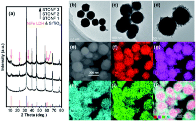
:![[thin space (1/6-em)]](https://www.rsc.org/images/entities/char_2009.gif) 5.4 for STONF 1, 2 and 3, respectively. PXRD patterns of the as-prepared samples are shown in Fig. 1a. All of diffraction peaks can be indexed as SrTiO3 (PDF# 86-0178) and NiFe LDH (PDF# 40-0215, shown by arrows). The widen diffraction peaks of NiFe LDH showed its nanocrystal size.
5.4 for STONF 1, 2 and 3, respectively. PXRD patterns of the as-prepared samples are shown in Fig. 1a. All of diffraction peaks can be indexed as SrTiO3 (PDF# 86-0178) and NiFe LDH (PDF# 40-0215, shown by arrows). The widen diffraction peaks of NiFe LDH showed its nanocrystal size.
Morphology of samples was investigated by TEM, SEM and EDS element mappings. As-prepared angular SrTiO3 (Fig. 1b) became spherical after growth of NiFe LDH (Fig. 1c and d), indicating SrTiO3 crystals were nano-scaled dissolving under alkaline NiFe LDH preparation system. Another difference STONFs from SrTiO3 was that there were nanoparticles growing on SrTiO3 core. EDS element mappings of STONFs (Fig. 1e–j and S1†) showed the existence of Sr, Ti, Ni and Fe belonging to SrTiO3 and NiFe LDH. With the increasing of content, the NiFe LDH incompletely coated (Fig. S1a and b†), homogeneously coated (Fig. 1c and d) on SrTiO3 for STONF 1 and 2, respectively. The NiFe LDH became self-aggregated for STONF 3.
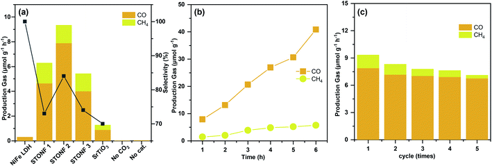
Photocatalytic CO2 reduction experiments were carried out under visible light irradiation (λ > 420 nm), and the results were summarized in Fig. 2a–c. As predicted by morphology, STONF 2 was completely core–shell structure, showed the highest CO yield (7.9 μmol g−1 h−1) and selectivity (84%). As showed in Fig. S2,† no liquid reduction products were detected. The CO yield was 1.7, 2.0, 25.7 and 8.8 times higher than that of STONF 1 (4.6 μmol g−1 h−1), STONF 3 (4.0 μmol g−1 h−1), as-prepared NiFe LDH (0.3 μmol g−1 h−1) and SrTiO3 (0.8 μmol g−1 h−1), respectively. As shown in Fig. S3,† SrTiO3 showed weak visible light absorption due to surface defects, which was responsible for its visible photocatalysis.20–24 The photocatalysis efficiency were roughly compared by CO yield. STONF 2 showed higher photocatalytic performance than reported CoAl LDH, MgAl LDH, ZnCr LDH, NiAl LDH, NiFe LDH, SrTiO3 based photocatalysts,25–38 as summarized in Table S1.†
In addition, blank contrast experiment was performed by using N2 to replace CO2, the catalyst was selected as STONF 2. No CO or CH4 were detected, which confirmed that CO and CH4 was originated from CO2.
The continuity and stability of STONF 2 were shown in Fig. 2b, c and S4.† From Fig. 2b, one can see the yields of CO and CH4 increased almost linearly with irradiation time and exhibited ascending CO selectivity. Recycling catalytic system with refreshed CO2 every 3 h for 5 times under continuous light irradiation was conducted to test the stability. From which one can see that the CO production kept stable (Fig. 2c). The morphology and phase composition (Fig. S4†) didn't change by comparation of that for STONF 2 before photocatalysis.
UV-vis absorption spectrum and transient photocurrent response measurement were conducted to study the photophysical properties (Fig. 3). STONFs showed visible light absorption. The photocurrent response (Fig. 3b) of STONFs was 2 > 1 > 3, which was in accordance with their photocatalysis performance. STONF 2 exhibited the highest photocurrent response, indicating the highest light utilization efficiency and the most photo-generated carriers.
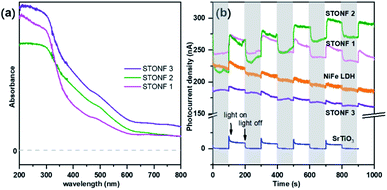 | ||
| Fig. 3 (a) UV-vis absorption spectrum and (b) transient photocurrent response of as-prepared catalysts. | ||
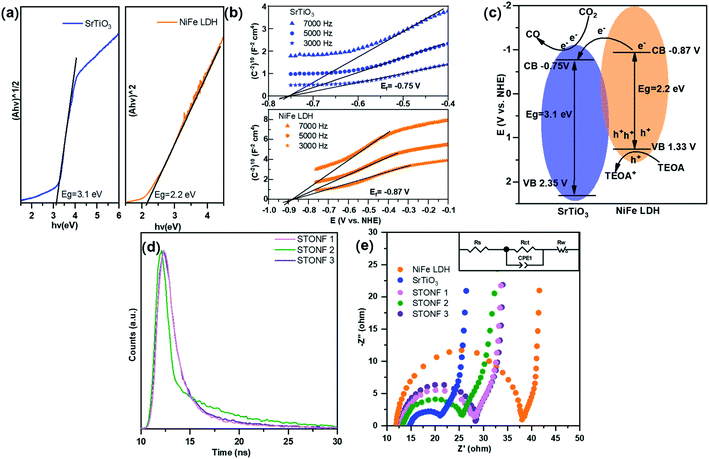
In order to shed light on the improved catalysis performance of STONFs, the band structures of as-prepared SrTiO3 and NiFe LDH were examined. The Tauc plots (Fig. 4a) that calculated from plots in UV-vis absorption spectrum showed the energy gap (Eg) of SrTiO3 and NiFe LDH were 3.1 eV and 2.2 eV, respectively. The flat band potentials (Ef) of SrTiO3 and NiFe LDH obtained by Mott–Schottky measurements (Fig. 4b) were −0.75 V and −0.87 V (vs. NHE), respectively. Combining Eg and Ef, band structure of STONF composites and photocatalytic mechanism were showed in Fig. 4c. The detailed calculation method was shown in ESI.† Induced by visible light, electrons in NiFe LDH shell were excited to conduction band, and accordingly holes situated in valence band. Then electrons rapidly transferred to conduction band of SrTiO3 core, and converted CO2 to CO. Meanwhile, holes were consumed by triethanolamine (TEOA). The well-matched band structure facilitated carriers separation, which was desirable for photocatalysis.
The results were further confirmed by transient photoluminescence decays (Fig. 4d). The corresponding fitting parameters were listed in Table S2.† The lifetime of STONFs was 3.19 ns, 5.03 ns and 2.82 ns for 1, 2 and 3, respectively. STONF 2 showed the longest lifetime, suggesting the highest separation and transportation efficiency.
The results of electrochemical impedance spectroscopy (EIS) and corresponding fitted circuit model were shown in Fig. 4e. The impedance curves consisted one capacitive loop in high frequency region and one Warburg diffusion line in low frequency region. The capacitive loop was assigned to charge transfer resistance (Rct) and this was related with photocatalysis. As shown in Table S3,† Rct of SrTiO3 (10.22 Ω cm−2) was much smaller than that of NiFe LDH (25.40 Ω cm−2), indicating SrTiO3 was a good electron transporter. Rct values were 2 < 1 < 3 (13.08 < 15.38 < 16.06 Ω cm−2), which was in accordance with their photocatalytic performance.
Considering the results of EIS and transient PL decays, it was obvious that integrating components with matched band structure can promote carriers separation and transportation efficiency. Photoelectron produced by NiFe LDH shell transferred to SrTiO3 core whose resistance was much lower than that of NiFe LDH. Therefore, the combination of e−/h+ pairs were prevented efficiently. SrTiO3 has merit of stability and is cheaper than noble metal that commonly used in photocatalyst modification strategy. Among all the samples in our experiment, STONF 2 owned complete core shell structure and exhibited most efficient electron transformation.
As deduced from TEM (Fig. 1b–d), SrTiO3 crystals were dissolved in nanoscale and thus the followed NiFe LDH growth was on the fresh crystal surface. It is well known that reducing interface defects, typically oxygen vacancies in oxide catalysts can decrease carriers recombination and thus increase the photocatalysis performance.20,39,40 So, it is necessary to study the oxygen vacancies in STONF 2. The ratio of Ti3+ and Ti4+ can reveal the oxygen vacancy contents. The reason was shown as follows. The lattice oxygen in SrTiO3 was released to the gas phase due to the dissociation of Ti–O bond, usually the surface Ti–O bond, thus forming oxygen vacancies (VO) and Ti3+, as denoted in eqn (1) and (2).15,41,42
 | (1) |
 | (2) |
So, X-ray photoelectron spectroscopy (XPS) was studied. The results were shown Fig. S5, S6,† 5a and b (high-resolution spectra for Ti 2p and O 1s). The peaks around 458.5 and 458.0 eV in the Ti 2p5/2 region are the characteristic signals of Ti4+ and Ti3+.43–45 The calculated relative Ti3+ species ratios were summarized in Table 1. The peak area ratio of Ti3+ and Ti4+ (R1 value) in STONF 2 was 0.73, which was lower than that in SrTiO3 (0.97), indicating less oxygen vacancies in STONF 2. This probably was due to the SrTiO3 crystals nano-scaled dissolution after NiFe LDH surface growth. The oxygen vacancy in the interface of SrTiO3 and NiFe LDH was successively decreased. This would increase the opportunity of direct bonding between interface atoms of two components. The two components share the interface O atoms, so direct bonding was based on breaking down H–O bonds for NiFe hydroxide. O species in NiFe LDH attributed from M–O (M = Ni, Fe), H–O, and O of interlayer Ac−.46,47
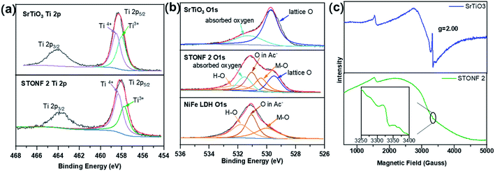 | ||
| Fig. 5 XPS spectra of (a) the Ti 2p region and (b) O 1s region for as-prepared catalysts; (c) EPR signals of SrTiO3 and STONF 2. | ||
| Catalyst | Ti4+ | Ti3+ | R1 | ||
|---|---|---|---|---|---|
| BE (eV) | Cont. (%) | BE (eV) | Cont. (%) | Cont. (Ti3+)/Cont. (Ti4+) | |
| SrTiO3 | 458.51 | 50.8% | 458.00 | 49.2% | 0.97 |
| STONF 1 | 458.33 | 53.0% | 457.79 | 47.0% | 0.89 |
| STONF 2 | 458.30 | 57.7% | 457.75 | 42.3% | 0.73 |
| STONF 3 | 458.34 | 53.3% | 457.76 | 46.7% | 0.88 |
As summarized in Table 2, STONF 2 showed smaller ratio of H–O and M–O contents (R2) (0.80) than bare NiFe LDH (1.08). This result indicated that the relative amount of H–O bonds decreased, which was consistency of deduction from Ti 2p analysis.48–50
| Catalyst | H–O | M–O | R2 | ||
|---|---|---|---|---|---|
| BE (eV) | Cont. (%) | BE (eV) | Cont. (%) | Cont. (H–O)/Cont. (M–O) | |
| NiFe LDH | 531.79 | 32.9% | 530.00 | 30.5% | 1.08 |
| STONF 1 | 532.04 | 23.9% | 529.50 | 26.6% | 0.88 |
| STONF 2 | 532.09 | 25.6% | 530.39 | 32.0% | 0.80 |
| STONF 3 | 532.10 | 14.62% | 529.48 | 13.3% | 1.09 |
In addition, X-band electron paramagnetic resonance spectroscopy (EPR) was also carried out to examine oxygen vacancies due to the existence of single electron in Ti3+. The results were shown in Fig. 5c. The intense and sharp signal in SrTiO3 and much weaker signal in STONF 2 at g = 2.00 indicated less oxygen vacancies in STONF 2,51–53 in accordance with the XPS results. Lower oxygen vacancies concentration would increase the opportunity of direct bonding between interface atoms of two components and successively increased the electron transportation and separation. This was probably one reason for the high catalysis performance of STONF 2.
4. Conclusions
In summary, SrTiO3@NiFe LDH core–shell composite was synthesized, and their photocatalytic CO2 reduction performance was studied. The photocatalyst STONF 2 exhibited enhanced CO2 reduction performance with CO yield of 7.9 μmol g−1 h−1. The yield was 25.7 times and 8.8 times higher than that of as-prepared NiFe LDH and SrTiO3 respectively, and also higher than most of LDH based photocatalysts. SrTiO3 and NiFe LDH had matched band structure. NiFe LDH shell served as light absorbent and generated e−/h+ pairs. Then electrons transferred onto the SrTiO3 core for CO2 reduction. STONFs owned merits of both components. Widened absorption spectrum was beneficial for carriers generation. Smaller charge transfer resistance and longer carriers lifetime indicated higher carriers separation and transportation efficiency. The complete coating, fewer oxygen vacancies at interface and tight combination increased the charge transportation and thus decreased carries recombination. These factors synergistically contributed to enhanced photocatalytic performance. This work will provide new insight for designing complementary multi-component photocatalysis system.Author contributions
Lian Zhu: conceptualization, investigation, methodology, project administration, visualization, writing – original draft. Zhengping Qiao: funding acquisition, resources, supervision, writing – review & editing.Conflicts of interest
There are no conflicts to declare.Acknowledgements
This work was supported by the National Natural Science Foundation of China (No. 21571193) and the Open Funds of the State Key Laboratory of Rare Earth Resources Utilization RERU2013012.Notes and references
- L. Bai, H. Huang, S. Yu, D. Zhang, H. Huang and Y. Zhang, J. Energy Chem., 2022, 64, 214–235 CrossRef.
- C. I. Ezugwu, S. Liu, C. Li, S. Zhuiykov, S. Roy and F. Verpoort, Coord. Chem. Rev., 2022, 450, 214245 CrossRef CAS.
- M. Humayun, C. Wang and W. Luo, Small Methods, 2021, 2101395 Search PubMed.
- H.-J. Son, C. Pac and S. O. Kang, Acc. Chem. Res., 2021, 54, 4530–4544 CrossRef CAS PubMed.
- S. Singh, A. Modak, K. K. Pant, A. Sinhamahapatra and P. Biswas, ACS Appl. Nano Mater., 2021, 4, 8644–8667 CrossRef CAS.
- K. Ren, S. Yue, C. Li, Z. Fang, K. A. M. Gasem, J. Leszczynski, S. Qu, Z. Wang and M. Fan, J. Mater. Chem. A, 2022, 10, 407–429 RSC.
- Q. Wang and K. Domen, Chem. Rev., 2020, 120, 919–985 CrossRef CAS PubMed.
- A. Behera, A. K. Kar and R. Srivastava, Mater. Horiz., 2022, 9, 607–639 RSC.
- V. Balakumar, S. Selvarajan, A. Baishnisha and S. Kathiresan, Appl. Surf. Sci., 2022, 577, 151924 CrossRef CAS.
- C.-J. Chang, J.-K. Chen, K.-S. Lin, C.-Y. Huang and C.-L. Huang, Int. J. Hydrogen Energy, 2021, 46, 11357–11368 CrossRef CAS.
- H. Wu, X. Y. Kong, X. Wen, S.-P. Chai, E. C. Lovell, J. Tang and Y. H. Ng, Angew. Chem., Int. Ed., 2021, 60, 8455–8459 CrossRef CAS PubMed.
- Z. Zhan, H. Wang, Q. Huang, S. Li, X. Yi, Q. Tang, J. Wang and B. Tan, Small, 2022, 18, 2105083 CrossRef CAS PubMed.
- K. Wang, T. Wang, Q. A. Islam and Y. Wu, Chin. J. Catal., 2021, 42, 1944–1975 CrossRef CAS.
- H. Boumeriame, E. S. Da Silva, A. S. Cherevan, T. Chafik, J. L. Faria and D. Eder, J. Energy Chem., 2022, 64, 406–431 CrossRef.
- R. A. De Souza, Curr. Opin. Solid State Mater. Sci., 2021, 25, 100923 CrossRef CAS.
- T. Takata, J. Jiang, Y. Sakata, M. Nakabayashi, N. Shibata, V. Nandal, K. Seki, T. Hisatomi and K. Domen, Nature, 2020, 581, 411–414 CrossRef CAS PubMed.
- T. Takata and K. Domen, J. Phys. Chem. C, 2009, 113, 19386–19388 CrossRef CAS.
- L. Mu, Y. Zhao, A. Li, S. Wang, Z. Wang, J. Yang, Y. Wang, T. Liu, R. Chen, J. Zhu, F. Fan, R. Li and C. Li, Energy Environ. Sci., 2016, 9, 2463–2469 RSC.
- L. Dong, H. Shi, K. Cheng, Q. Wang, W. Weng and W. Han, Nano Res., 2014, 7, 1311–1318 CrossRef CAS.
- H. Tan, Z. Zhao, W.-b. Zhu, E. N. Coker, B. Li, M. Zheng, W. Yu, H. Fan and Z. Sun, ACS Appl. Mater. Interfaces, 2014, 6, 19184–19190 CrossRef CAS PubMed.
- U. Sulaeman, S. Yin and T. Sato, Adv. Nanopart., 2013, 2, 01–05 CrossRef.
- H. Che, J. Chen, K. Huang, W. Hu, H. Hu, X. Liu, G. Che, C. Liu and W. Shi, J. Alloys Compd., 2016, 688, 882–890 CrossRef CAS.
- S.-F. Yang, C.-G. Niu, D.-W. Huang, H. Zhang, C. Liang and G.-M. Zeng, Environ. Sci.: Nano, 2017, 4, 585–595 RSC.
- L. Tong, L. Ren, A. Fu, D. Wang, L. Liu and J. Ye, Chem. Commun., 2019, 55, 12900–12903 RSC.
- S. Shoji, G. Yin, M. Nishikawa, D. Atarashi, E. Sakai and M. Miyauchi, Chem. Phys. Lett., 2016, 658, 309–314 CrossRef CAS.
- S. Wang, K. Teramura, T. Hisatomi, K. Domen, H. Asakura, S. Hosokawa and T. Tanaka, ACS Appl. Energy Mater., 2020, 3, 1468–1475 CrossRef CAS.
- S. Wang, K. Teramura, T. Hisatomi, K. Domen, H. Asakura, S. Hosokawa and T. Tanaka, ACS Sustainable Chem. Eng., 2021, 9, 9327–9335 CrossRef CAS.
- K.-i. Katsumata, K. Sakai, K. Ikeda, G. Carja, N. Matsushita and K. Okada, Mater. Lett., 2013, 107, 138–140 CrossRef CAS.
- S. Kumar, L. J. Durndell, J. C. Manayil, M. A. Isaacs, C. M. A. Parlett, S. Karthikeyan, R. E. Douthwaite, B. Coulson, K. Wilson and A. F. Lee, Part. Part. Syst. Charact., 2018, 35, 1700317 CrossRef.
- Y.-f. Miao, R.-t. Guo, J.-w. Gu, Y.-z. Liu, G.-l. Wu, C.-p. Duan and W.-g. Pan, ACS Appl. Nano Mater., 2021, 4, 4902–4911 CrossRef CAS.
- C. Ning, Z. Wang, S. Bai, L. Tan, H. Dong, Y. Xu, X. Hao, T. Shen, J. Zhao, P. Zhao, Z. Li, Y. Zhao and Y.-F. Song, Chem. Eng. J., 2021, 412, 128362 CrossRef CAS.
- S. Tonda, S. Kumar, M. Bhardwaj, P. Yadav and S. Ogale, ACS Appl. Mater. Interfaces, 2018, 10, 2667–2678 CrossRef CAS PubMed.
- Y. Wu, Y. Gong, J. Liu, T. Chen, Q. Liu, Y. Zhu, L. Niu, C. Li, X. Liu, C. Q. Sun and S. Xu, J. Alloys Compd., 2020, 831, 154723 CrossRef CAS.
- J. Xu, X. Liu, Z. Zhou, L. Deng, L. Liu and M. Xu, Energy Fuels, 2021, 35, 16134–16143 CrossRef CAS.
- J. Xu, X. Liu, Z. Zhou, L. Deng, L. Liu and M. Xu, Energy Fuels, 2021, 35, 10820–10831 CrossRef CAS.
- S. Zhao, D. Pan, Q. Liang, M. Zhou, C. Yao, S. Xu and Z. Li, J. Phys. Chem. C, 2021, 125, 10207–10218 CrossRef CAS.
- X. Zhao, X. Zhao, I. Ullah, L. Gao, J. Zhang and J. Lu, Catal. Lett., 2021, 151, 1683–1692 CrossRef CAS.
- S. Kumar, M. A. Isaacs, R. Trofimovaite, L. Durndell, C. M. A. Parlett, R. E. Douthwaite, B. Coulson, M. C. R. Cockett, K. Wilson and A. F. Lee, Appl. Catal., B, 2017, 209, 394–404 CrossRef CAS.
- S. Jia, J. Gao, Q. Shen, J. Xue, Z. Zhang, X. Liu and H. Jia, J. Mater. Sci.: Mater. Electron., 2021, 32, 13369–13381 CrossRef CAS.
- Y. Ham, T. Hisatomi, Y. Goto, Y. Moriya, Y. Sakata, A. Yamakata, J. Kubota and K. Domen, J. Mater. Chem. A, 2016, 4, 3027–3033 RSC.
- C.-Y. Guo and X. Qi, Mater. Des., 2019, 179, 107888 CrossRef CAS.
- Z. Zhang, H. Yan, S. Wang, M. Wang, L. Ren, C. Chen and K. Jin, J. Mater. Sci., 2019, 54, 4780–4787 CrossRef CAS.
- R. Hong, C. Deng, M. Jing, H. Lin, C. Tao and D. Zhang, Opt. Mater., 2019, 95, 109224 CrossRef CAS.
- Y. Zhao, M. Zhang, W. Wang, W. Song, K. Jiang and X. Zhang, J. Mater. Sci.: Mater. Electron., 2021, 32, 22910–22920 CrossRef CAS.
- Y. Qin, F. Fang, Z. Xie, H. Lin, K. Zhang, X. Yu and K. Chang, ACS Catal., 2021, 11, 11429–11439 CrossRef CAS.
- H. Sun, W. Zhang, J.-G. Li, Z. Li, X. Ao, K.-H. Xue, K. K. Ostrikov, J. Tang and C. Wang, Appl. Catal., B, 2021, 284, 119740 CrossRef CAS.
- S. Liu, H. Zhang, E. Hu, T. Zhu, C. Zhou, Y. Huang, M. Ling, X. Gao and Z. Lin, J. Mater. Chem. A, 2021, 9, 23697–23702 RSC.
- T. Han, Y. Wei, X. Jin, H. Jiu, L. Zhang, Y. Sun, J. Tian, R. Shang, D. Hang and R. Zhao, J. Mater. Sci., 2019, 54, 7119–7130 CrossRef CAS.
- L. Geng, P. Zhu, Y. Wei, R. Guo, C. Xiang, C. Cui and Y. Li, Cellulose, 2019, 26, 2833–2847 CrossRef CAS.
- N. Cai, M. Chen, M. Liu, J. Wang, L. Shen, J. Wang, X. Feng and F. Yu, J. Mol. Liq., 2019, 289, 111060 CrossRef CAS.
- Q. Qin, T. Liu, J. Zhang, R. Wei, S. You and Y. Xu, J. Hazard. Mater., 2021, 419, 126447 CrossRef CAS PubMed.
- H. Trabelsi, M. Bejar, E. Dhahri, M. P. F. Graca, M. A. Valente, M. J. Soares and N. A. Sobolev, Appl. Surf. Sci., 2017, 426, 386–390 CrossRef CAS.
- C. Foo, Y. Li, K. Lebedev, T. Chen, S. Day, C. Tang and S. C. E. Tsang, Nat. Commun., 2021, 12, 661 CrossRef CAS PubMed.
Footnote |
| † Electronic supplementary information (ESI) available: TEM, SEM and element mappings of STONFs, characterization of 5-cycle post-catalysis STONF 2, CO2 reduction performance of other photocatalysts, transient PL decays fitting parameters and XPS survey spectrum. See DOI: 10.1039/d2ra01178f |
| This journal is © The Royal Society of Chemistry 2022 |

