 Open Access Article
Autonomous-healing and smart anti-corrosion mechanism of polyurethane embedded with a novel synthesized microcapsule containing sodium dodecyl sulfate as a corrosion inhibitor
Iman Azamian ,
Saeed Reza Allahkaram
 * and
Sadegh Rezaee
School of Metallurgy and Materials Engineering, College of Engineering, University of Tehran, Tehran, Iran. E-mail: akaram@ut.ac.ir
First published on 11th May 2022
Abstract
The self-healing and smart anti-corrosion behavior of a polyurethane coating enhanced with micro-sized capsules have been investigated. An in situ polymerization technique was employed to synthesize a novel microcapsule containing sodium dodecyl sulfate (SDS) as a corrosion inhibitor in linseed oil (LO). FE-SEM, FT-IR and TG analysis were used to characterize the prepared microcapsules. The capsules were separately embedded in polyurethane at 1, 4 and 7 wt% and the coating properties were investigated through the water absorption rate and pull-off adhesion strength. The scratched coating was then subjected to 3.5 wt% NaCl solution to investigate the self-healing ability. Electrochemical measurements were carried out by means OCP, EIS and potentiodynamic polarization and the inhibition mechanism of SDS was discussed in terms of interfacial interactions. Despite the adhesion strength, a positive effect was observed for the water uptake, after addition of the microcapsules. 4 wt% of LO/SDS microcapsules showed the best results as its inhibition efficiency was more than 90% compared to single linseed oil capsules. EDS mapping was also employed to verify the successful release and distribution of the SDS, when subjected to scratching.
1. Introduction
The degradation of metals caused by corrosion phenomena has become a problem of worldwide significance, and usually leads to functionality failure and serious economic loss.1 There are several approaches to the matter of protection against corrosion, including cathodic protection, corrosion inhibitors and surface coating, which differ based on the characteristics of the system.2 One of the most common and effective strategies is the application of a protective coating that isolates the underlying substrate from aggressive mediums. Among them, organic coatings have been of much interest in the past decades. However, these coatings are highly prone to be failed when subjected to mechanical abrasions. The mechanical damages could open a path for localized penetration of aggressive medium, leading to the initiation of corrosion on the metallic substrate. The detriment caused by external factors is usually at the scale of micro or nano, and therefore, it is hard to monitor the initiation of anodic reactions on the surface. Therefore, self-healing coating as a guest–host system for active corrosion protection of metallic substrate has been proposed.3–8Capsule-based systems have been utilized frequently to achieve active protection due to their ability for smart releasing of the healing material at the time of need.9–14 Micro/nanocapsules are dispersed through the matrix as storage units for the healing agent that are ready to be freed when required.15,16 The most important part of this technique is the right selection of material for both shell and an incorporated agent inside the capsule.17,18 Variety of materials have been used for the core part of the capsule such as drying oil,19,20 pore blocking agents21,22 and corrosion inhibitors.23,24 At the same time, different types of shells such as polyurea,25 epoxy,26–28 polyurethane29,30 and poly(urea-formaldehyde)31–33 could be synthesized. Among them poly(urea-formaldehyde) has shown a proper distribution and uniformity in the polymer matrix and also has been strong enough to remain intact in the process of application.34 In addition, many researches have used linseed oil as the core material that can be polymerized into a solid form. Linseed oil contains a high percentage of polyunsaturated fatty acids that can be oxidized to form a three-dimensional network and seal the matrix defects caused by mechanical damages.35
Recently, the use of corrosion inhibitors as the core material has drawn much attention, regarding their self-healing capability on the matter of corrosion properties. Siva et al.,36 reported the effective healing ability of urea formaldehyde (UF) microcapsules loaded with mercaptobenzothiazole (MBT) as core material and demonstrated that the self-healing system could maintain protection in the corrosive environment for the further 15 days. In another work,37 Najjar et al. utilized silica encapsulated isophoronediisocyanate (IPDI) as the active healing agent in a polyurethane coating and reported an almost full recovery and enhancement of the thermal stability. Mahmoudian et al.38 also investigated the effect of anticorrosion performance of industrial epoxy and polyurethane coatings at the presence of linseed oil containing nano-sized capsules, with potassium ethyl xanthate and benzotriazole as healing agent on the copper metal films and reported a synergetic effect at the optimum level of 3% and 5% linseed oil and anticorrosion agent, respectively.
In this paper, anticorrosion effectiveness of novel poly urea-formaldehyde (PUF) microcapsule filled with linseed oil containing sodium dodecyl sulfate (SDS) as the active core material in an industrial polyurethane coating was investigated. The significance of this work is the development of a novel capsule that can endow a double-protection capability to the system through both the barrier effect of the drying oil and anticorrosion performance of the organic corrosion inhibitor. Recent investigations39 have demonstrated the potential application of SDS as a corrosion inhibitor for mild steel in an aqueous solution of 3.5% NaCl and proved its anticorrosion performance against aggressive media. Such a system can provide active protection against both mechanical damages and corrosive mediums. In this work, a simple procedure was used to synthesize the PUF/SDS microcapsules based on an in situ polymerization. The characteristics of the capsules were investigated via thermogravimetric analysis (TGA), Fourier transforms infrared spectroscopy (FT-IR). Scanning electron microscopy (SEM) was also used to confirm the integrity of microcapsules and coating matrix. Elemental mapping was recorded through Energy-Dispersive X-ray Spectrometer (EDS) to confirm the presence of inhibitor loaded capsules in the healing position. The self-healing behavior of the coatings was evaluated by open circuit potential (OCP), potentiodynamic polarization (PP) and electrochemical impedance spectroscopy (EIS).
2. Experimental
2.1 Material
Sodium dodecyl sulfate (SDS) and linseed oil (LO) were used as healing agent in analytical grade which were purchased from Sigma Aldrich. Urea, formaldehyde, ammonium chloride, resorcinol and polyvinyl alcohol were all used for encapsulating the core material which were also purchased from Sigma Aldrich. Hydrochloric acid obtained from Merck was used for controlling the pH of the solution. Deionized water was the base material for emulsification. Acetone and ethanol were used for washing procedure of the synthesized capsules. Commercial grade of polyurethane and its hardener (ALCO-2703) together with ALCO-2700 as the thinner were obtained from Alvan paint and resin Co. and were used as the polymer matrix. All of the chemicals were used without further purification.2.2 Synthesize of microcapsules
PUF microcapsules were synthesized based on an oil-in-water emulsification through in situ polymerization technique. Encapsulation procedure was similar to the process suggested by Lang et al.40 for linseed oil micro-encapsulation. 5 mL of 5 wt% PVA aqueous solution as the surfactant was added to 130 mL of deionized water. 2.5 g urea as the first monomer, 0.25 g resorcinol as the cross-linker and 0.25 g ammonium chloride as the hardener were added to the initial solution while stirring to dissolve at 25 °C. The pH of the solution was carefully monitored and maintained at 3 ± 0.02 through a pH meter by addition of approximately 1 wt% hydrochloric acid aqueous solution. The solution was then transferred to a 250 mL two-necked flask, which was suspended in temperature-controlled water bath. A polytetrafluoroethylene (PTFE) mechanical stirrer with a rate of 900 rpm was used. For type 1 capsules, 30 mL linseed oil was slowly added to form an emulsion and allowed to stabilize for 20 minutes under agitation. After the addition of 6.4 g of 37 wt% formaldehyde aqueous solution as the second monomer, the temperature was gradually increased to 55 °C while stirring at 600 rpm for 4 h until the capsule walls were completely polymerized. For type 2 microcapsules, 5 g of SDS powder was dissolved in 25 g of linseed oil and the solution was added as the healing agent. Other parts of the procedure were the same as the type 1 microcapsule. A scheme of the configuration of the chemical compounds for formation of the microcapsules is presented in Fig. 1.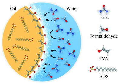 | ||
| Fig. 1 A schematic of the capsule shell polymerization and healing agent entrapment in the core content. | ||
After 4 h, the contents were cooled down to ambient temperature and were set aside for 1 h for separation of oil and aqueous phases. The aqueous phase was disposed from the bottom, and the rest of the suspension was centrifuged (Behsan HB 207) at 4000 rpm until the capsules, residual aqueous phase and the unpolymerized urea-formaldehyde were separated. The capsules were rinsed and washed with deionized water, ethanol and acetone for at least seven times. Finally, after 72 h of drying at room temperature the microcapsules were ready to be directly added to the resin. Fig. 2 illustrates a schematic of in situ polymerization procedure used for synthesizing the LO/SDS microcapsules.
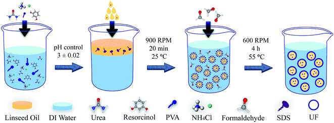 | ||
| Fig. 2 Schematic of the synthesize procedure for LO/SDS microcapsules using in situ polymerization technique. | ||
2.3 Fabrication of self-healing polyurethane coating
Polyurethane resin and its hardener with 6![[thin space (1/6-em)]](https://www.rsc.org/images/entities/char_2009.gif) :
:![[thin space (1/6-em)]](https://www.rsc.org/images/entities/char_2009.gif) 1 ratio were mixed with the thinner (25 wt% of resin) to dilute the prepared paint. Before addition of the thinner to the mixture, microcapsules were dispersed in the thinner in 1 wt%, 4 wt% and 7 wt% of the paint and then mixed in 200 rpm agitation rate with an ultrasonic probe. After addition of the thinner to the paint, it was mixed with a mechanical stirrer (200 rpm) until an appropriate dispersion of the capsules was achieved. A Q235 carbon steel was used as the substrate and was prepared in 2.5 × 5 cm2 pieces with 2 mm thickness. After applying the coatings using a painting brush on steel samples, they were maintained at room temperature to dry completely. Since no immersion test was intended, only one side of the metal was coated. Before applying the coating, the specimens were abraded with emery papers from 80 to 1000 grades and then washed with distilled water and acetone.
1 ratio were mixed with the thinner (25 wt% of resin) to dilute the prepared paint. Before addition of the thinner to the mixture, microcapsules were dispersed in the thinner in 1 wt%, 4 wt% and 7 wt% of the paint and then mixed in 200 rpm agitation rate with an ultrasonic probe. After addition of the thinner to the paint, it was mixed with a mechanical stirrer (200 rpm) until an appropriate dispersion of the capsules was achieved. A Q235 carbon steel was used as the substrate and was prepared in 2.5 × 5 cm2 pieces with 2 mm thickness. After applying the coatings using a painting brush on steel samples, they were maintained at room temperature to dry completely. Since no immersion test was intended, only one side of the metal was coated. Before applying the coating, the specimens were abraded with emery papers from 80 to 1000 grades and then washed with distilled water and acetone.
The final thickness of the cured coating with and without the presence of microcapsules was 130 ± 5 μm. In addition, according to the ASTM D3363-92, three samples, including neat polyurethane, 7 wt% LO and 7 wt% LO/SDS showed the same pencil hardness of HB, which is reasonable since the amount of OH groups and consequently urethane linkages do not change in different samples.
2.4 Characterization of microcapsules
The FTIR spectra of linseed oil (LO) and linseed oil/sodium dodecyl sulfate (LO/SDS) microcapsules were recorded using Thermo-AVATAR instrument to identify their chemical composition.Thermogravimetric analysis were carried out using a TA-Q600 analyzer for pure urea-formaldehyde, linseed oil and SDS in a controlled nitrogen environment. Thermal stability of substances were investigated at heating rate of 5 °C min−1, between 25 to 500 °C.
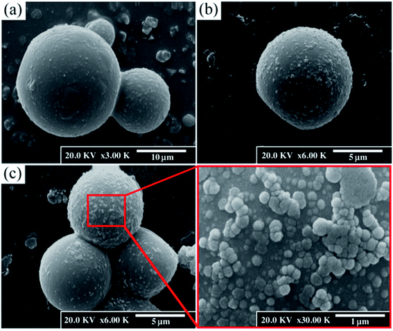
A Hitachi S-4160 field-emission scanning electron microcopy was used to investigate the integrity and surface morphology of urea-formaldehyde microcapsules. The size of the microcapsules were measured using Image J software. Morphology and elemental mapping of the scratch was also investigated using a FE-SEM equipped with EDS in order to confirm the healing ability of the SDS loaded microcapsules.
2.5 Coating properties
The adhesion strength of the microcapsule-embedded coatings was measured through a pull-off test on the intact samples using an Elcometer-108. The cylindrical dollies were applied on three different points of each sample and were vertically pulled off after the glue was cured at room temperature for 24 hours.Water absorption test were carried out using gravimetric technique. Five specimens were used for each sample for better validation of the data. Specimens were immersed in distilled water at 25 °C. After specific intervals they were removed from water, dried and weighted until it reached a stable value. The water absorption value was calculated using the following equation;
 | (1) |
2.6 Evaluation of corrosion protection
Customized cell made of poly methyl methacrylate (PMMA) was used to evaluate the electrochemical behavior of the encapsulated coating. An X-shaped graze was scratched on the coating until the substrate was exposed, letting the microcapsules to commence healing process. After 24 h, the center of the scratch was fixed on the cell with an exposed area of 1.7 cm2. The samples were subjected to 3.5 wt% NaCl solution at ambience temperature. The OCP with respect to the saturated calomel electrode (SCE) was recorded for 28 days to monitor the activity of the surface during the healing process using a high input impedance voltmeter (Ziegler RM-16) utilized with a data logger plugin.The corrosion resistance of the microcapsule-embedded polyurethane coating was investigated via the electrochemical impedance analysis. The tests were carried out using a Solarton SI 1260 in a 3.5 wt% NaCl solution after four different periods of 2, 7, 14 and 28 days. For all the electrochemical measurements, a three-electrode set-up was used including SCE and platinum electrode as the reference and counter electrodes, respectively. The measurements were performed in a frequency range of 100 kHz to 10 mHz with a sinusoidal potential perturbation of 10 mV versus OCP. The obtained data was fitted using Zview software.
After 28 days of exposure, the corrosion potential and current density were measured using the polarization method, in order to investigate the effect of localized attacks on the polymer matrix. The tests were carried out using EG&G-237A and the set up was the same as for the impedance analysis. The potential was scanned with a rate of 10 mV min−1 from −300 mV to approximately +800 mV with respect to the OCP until no obvious change was observed in the curve.
3. Results and discussion
3.1 Characterization of synthesized microcapsules
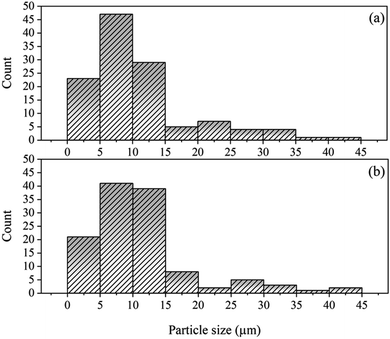
Fig. 4 shows the histograms of the particle size distribution of the synthesized LO and LO/SDS microcapsule. It show that the LO/SDS microcapsules have a mean size in the 1 to 45 μm range and the size of more than 50% of them are less than 15 μm. LO capsules had approximately the same size distribution as the inhibitor loaded ones.
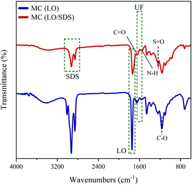
![[double bond, length as m-dash]](https://www.rsc.org/images/entities/char_e001.gif) O at 1648 cm−1, which are the characteristic peaks of pure urea-formaldehyde, are observed for both types of microcapsules. A sign of a shallow broad band of N–H stretching vibration is also detected between 3100 and 3500 cm−1, which is attributed to the secondary amides that are formed in the wall forming process.40,41 Characteristic peaks of linseed oil as the core content are observed at 1746 cm−1, 1648 cm−1 and 1164 cm−1, which are ascribed to C
O at 1648 cm−1, which are the characteristic peaks of pure urea-formaldehyde, are observed for both types of microcapsules. A sign of a shallow broad band of N–H stretching vibration is also detected between 3100 and 3500 cm−1, which is attributed to the secondary amides that are formed in the wall forming process.40,41 Characteristic peaks of linseed oil as the core content are observed at 1746 cm−1, 1648 cm−1 and 1164 cm−1, which are ascribed to C![[double bond, length as m-dash]](https://www.rsc.org/images/entities/char_e001.gif) O, C
O, C![[double bond, length as m-dash]](https://www.rsc.org/images/entities/char_e001.gif) C and C–O stretching vibrations, respectively.36 Another peak is detected at 3010 cm−1, which is due to the presence of –CH and –CH2 in the fatty acids,.42 The 1460 cm−1 peak and the broad band between 2850 cm−1 and 3000 cm−1 are attributed to the sp3 C–H stretching and bending vibration.40 As it can be seen, the FTIR spectrum of both LO and LO/SDS microcapsules show the characteristic peaks of both pure polyurea-formaldehyde and pure linseed oil, which verifies the encapsulation process.
C and C–O stretching vibrations, respectively.36 Another peak is detected at 3010 cm−1, which is due to the presence of –CH and –CH2 in the fatty acids,.42 The 1460 cm−1 peak and the broad band between 2850 cm−1 and 3000 cm−1 are attributed to the sp3 C–H stretching and bending vibration.40 As it can be seen, the FTIR spectrum of both LO and LO/SDS microcapsules show the characteristic peaks of both pure polyurea-formaldehyde and pure linseed oil, which verifies the encapsulation process.
For LO/SDS microcapsule, characteristic peaks of a S![[double bond, length as m-dash]](https://www.rsc.org/images/entities/char_e001.gif) O stretching vibration at 1216 cm−1, a C–H symmetric stretching vibration at 1466 cm−1 and a C–H asymmetric stretching vibration at 2916 cm−1 were observed.43 This confirms that the SDS is embedded in the linseed oil, forming the double agent core material. Therefore, the FTIR results prove that both LO and LO/SDS microcapsules are successfully synthesized.
O stretching vibration at 1216 cm−1, a C–H symmetric stretching vibration at 1466 cm−1 and a C–H asymmetric stretching vibration at 2916 cm−1 were observed.43 This confirms that the SDS is embedded in the linseed oil, forming the double agent core material. Therefore, the FTIR results prove that both LO and LO/SDS microcapsules are successfully synthesized.
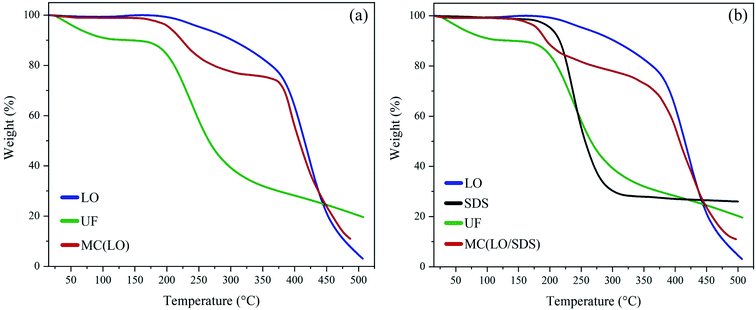
Fig. 6b shows the thermograms for LO/SDS microcapsules and its components. At 180 °C thermal decomposition of SDS started, which indicated that the LO/SDS capsules were only functional until temperatures below 180 °C. As it can be seen, two major mass losses at 170 and 400 °C are observed, which are attributed to urea-formaldehyde and linseed oil, respectively. LO/SDS microcapsules had approximately the same core content as LO microcapsules in such a way that almost 78 wt% of them stayed intact at temperatures around 400 °C.
3.2 Performance of microcapsule embedded coating
In order to investigate the effect of embedded microcapsules on the adhesion property of polyurethane coating on the steel surface, pull-off test was carried out and the results are shown in the Fig. 7. It was found that the addition of the capsules to the polymer matrix decreased the adhesion strength of the coating on the metal surface. This is probably due to the fact that some of the embedded capsules may settle on the metal/coating interface and reduce the contact surface between the polyurethane and steel. Increasing the percentage the microcapsules results in more defects on the interface and hence more loss in adhesion strength. Both LO and LO/SDS microcapsules had approximately the same effect on the adhesion property of the coating.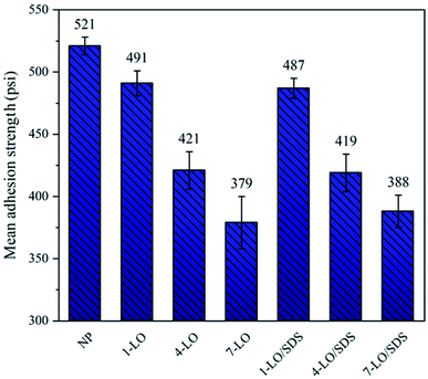 | ||
| Fig. 7 The pull-off adhesion results for polyurethane coating embedded with various concentrations of the microcapsules. | ||
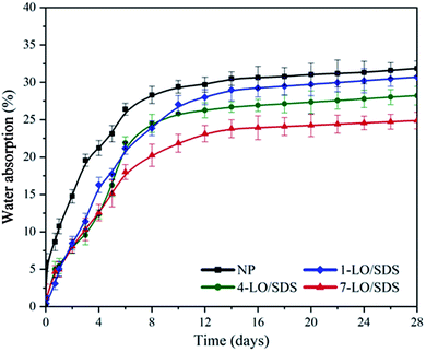
Water absorption rate of polyurethane coating embedded with microcapsules was evaluated via gravimetric method. Three samples were used for each material and the results are shown in Fig. 8. Since the microcapsules were not activated in an intact coating the type of healing agent did not affect the results of the test. Therefore only LO/SDS capsules were used in this experiment. As shown in the figure, the water absorption of all the samples were less than 30 wt% and they all reached the steady state after about 9 days. The water uptake was reduced with increasing the percentage of microcapsules in the coating. This shows that there is a good entanglement between the shell surface of the capsule and the polyurethane matrix, which outcomes in less interfacial free energy. The results of this experiment showed that the capsulated coatings had a suitable water resistance.
3.3 Smart anti-corrosive performance
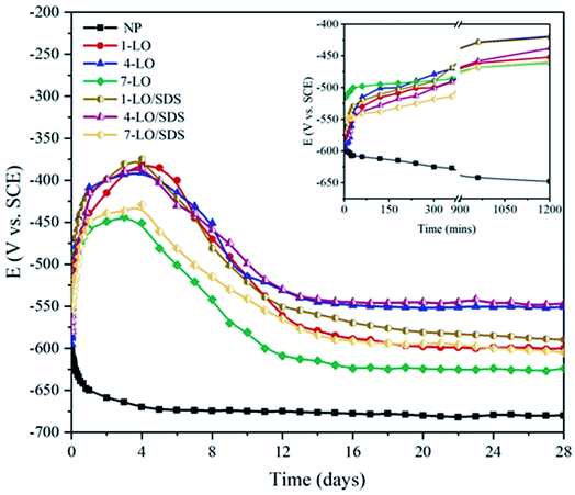
Open circuit potential of the scratched coating exposed to 3.5 wt% aqueous solution was recorded for 28 days in order to monitor the activity of the system. Fig. 9 shows the OCP variation profiles for the different concentrations of LO and LO/SDS microcapsules. It was observed that with the addition of microcapsules to the coating, the free potential of the system shifted to more positive values, resulting in a less active surface on the substrate. This shows that the released healing agents have improved the barrier effect of the coating on the scratched part.36 As it can be seen, all the capsulated coatings experience, an initial potential increased for approximately 5 days and then decreased until the steady state condition. Both LO and LO/SDS at 4 wt% showed the best values for OCP (around −500 mV) which is approximately +200 mV potential shift. In addition, at 4 wt%, both capsules reached the steady-state more quickly than others. However when the capsules were embedded in 7 wt% of the polyurethane coating the steady-state potential was −623 mV for LO and −611 mV for LO/SDS after 28 days indicating less protective property of the coating compared to 4 wt%. This behavior is a bit controversial since the more linseed oil embedded in microcapsules, should generally mean more oil to dry. Compared to 4 wt%, the potential drop at 7 wt% is due to the agglomeration of microcapsules in the coating leading to a non-uniform dispersion along the polymer matrix, which results in a weak healing effect.The effect of SDS on the healing ability of microcapsules was recognizable from OCP measurements as approximately a 40 mV potential shift was observed in the 28 days potential of LO and LO/SDS microcapsules at a specific concentration. However, for ensuring an explicate effect of SDS, potentiodynamic polarization and EIS analysis were performed.
Potentiodynamic polarization scan were carried out for 1, 4 and 7 wt% of LO and LO/SDS microcapsule embedded coating after 28 days of exposure to 3.5 wt% NaCl solution at room temperature. The polarization curves for LO and LO/SDS specimens are shown in Fig. 10a and b, respectively. An active-passive behavior was observed for all the specimens. Compared to the control sample, both anodic and cathodic branches of the curves were affected after the addition of the microcapsules. However, based on the figures, the reduction in anodic reactions were more pronounced than the cathodic ones, indicating the effectiveness of the capsules in the hindrance of the metal dissolution processes. Potentiodynamic parameters such as corrosion potential (Ecorr), corrosion current density (icorr), inhibition efficiency (IE%) and anodic and cathodic slops were calculated through Tafel extrapolation and are shown in Table 1. The corrosion inhibition efficiency is calculated according to the following equation;44
 | (2) |
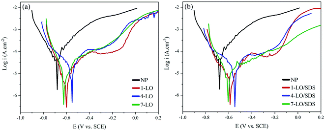 | ||
| Fig. 10 Potentiodynamic polarization curves for different concentrations of (a) LO and (b) LO/SDS embedded coatings after 28 days of exposure to 3.5 wt% NaCl. | ||
| Sample | Ecorr (mV) | Icorr (μA cm−2) | βa | −βc | η (%) | |
|---|---|---|---|---|---|---|
| NP | −680 | 56.2 | 0.42 | 0.27 | — | |
| LO | 1% | −620 | 18.15 | 0.53 | 0.15 | 67.7 |
| 4% | −521 | 16.25 | 0.45 | 0.22 | 71.09 | |
| 7% | −644 | 15.57 | 0.39 | 0.07 | 72.3 | |
| LO/SDS | 1% | −588 | 7.42 | 0.21 | 0.09 | 86.8 |
| 4% | −497 | 6.69 | 0.29 | 0.11 | 88.1 | |
| 7% | −565 | 9.53 | 0.38 | 0.08 | 83.05 | |
Both types of capsules resulted in reduction of icorr, and this effect was intensified as the concentration of the embedded microcapsules increased. The lowest corrosion inhibition efficiency was more than 65% compared to the control sample. The consequence of the addition of linseed oil as the general healing agent to the scratched coating is that it would restore the protection by recovering the barrier effect of the coating at the position of the scratch. Therefore a huge difference in icorr is expected after the addition of the single agent capsules, which in this case the IE% became more than 72% for 7 wt% LO embedded samples. However, the difference between 4 wt% and 7 wt% of LO capsules was not that significant. This might be because of the fact that higher percentage of the LO capsules might result in unequal distribution or partial agglomeration of the micro particles.
Although a sufficient inhibition efficiency was observed for linseed oil loaded capsules, we suggest that this protection is not stable since according to the water absorption results, water uptake for most of the samples were around 20 wt% of the PU coating and this is for the intact specimens and not the ones with artificial scratches. Therefore, it is reasonable to assume that the absorbed medium to the coating, which comprises corrosive agents such as Cl− ions, could eventually reach the surface and once again trigger the metal dissolution reactions on the surface.45 Hence, it is important to have a contingency plan, when the polymerization reaction of linseed oil and a physical barrier layer are not enough for guarantying the corrosion protection. Therefore, presence of the SDS molecules on the metal surface as the second corrosion inhibition mechanism is necessary.
Ecorr for the LO/SDS embedded coatings changed in the range of ±85 mV with respect to the LO loaded capsules, which indicates the mixed typed behavior of the SDS as the corrosion inhibitor. Compared to the control sample, more than +120 mV shift was observed in the corrosion potential, which shows the effect of SDS on the hindrance of anodic reactions on the metal surface. With the presence of SDS as the second healing agent, a secondary protection would be active in case if the aggressive medium penetrates the matrix in the process of healing or after a certain amount of time. Sodium dodecyl sulfate is a polar molecule that tends to move towards the surface as the result of electrostatic attraction from the metal. The SDS behavior on the surface is directly depended on the type of the oxide film on the metal. Charge of the metal and the donor–acceptor interaction between the polar groups and metal species, which is well explained in the EIS section, based on the concept of the electrical double layer. The outcomes of potentiodynamic polarization showed that all of the SDS loaded capsules resulted in more than 83% inhibition efficiency. The best performance was observed for the 4 wt% sample with 88.1% efficiency.
The corrosion behavior of the carbon steel in the presence and absence of the various percentages of healing microcapsules was investigated by the electrochemical impedance spectroscopy technique. As described before, the samples were artificially scratched and exposed to a 3.5 wt% NaCl solution for a period of 28 days. Because of the non-destructive nature of EIS method, each sample was tested in the 2, 7, 14 and 28 days intervals. The results are presented as Nyquist and Bode plots. Based on the characteristics of each sample, electrical equivalent circuits (EEC) were used to model and calculate the numerical values corresponding to the physical and chemical properties of the system under investigation (Fig. 11).
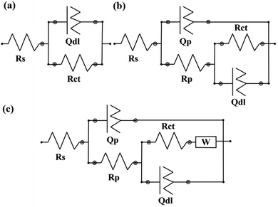 | ||
| Fig. 11 Electrical equivalent circuits used for fitting the EIS data. (a) neat coating, (b) after 7 days of exposure (c) after 28 days of exposure. | ||
Fig. 12 shows the impedance spectra for the neat polyurethane coating as the control sample for evaluating the self-healing ability of capsulated systems. The obtained data for the neat coating was fitted using a [Rs(RctQdl)] equivalent circuit, which is shown in Fig. 11a. Rs is the resistance of the solution while Rct and Qct represent the charge transfer resistance in the interface and the double layer capacitance, respectively. For all the equivalent circuits, a constant phase element (Q or CPE) was used instead of a pure capacitor to describe the non-ideal behavior of the system due to the presence of physical, chemical, or geometrical heterogeneities on the interfaces and it is calculated using the following equation;46
| C = (Y0R1−n)1/n | (3) |
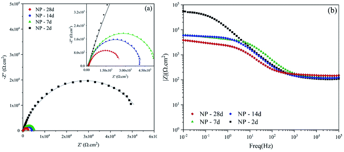 | ||
| Fig. 12 (a) Nyquist and (b) Bode plots of scratched neat polyurethane after various exposure times to 3.5 wt% NaCl. | ||
The EEC related to the 2 days exposure of NP is a single time constant circuit showing that the barrier property of the coating is completely lost as the result of the scratch. However, after 7 days of exposure, the obtained data offered a great fit with a double time constant EEC of [Rs(Qp[Rp(RctQct)])]. Rp and Qp are the pore resistance and pseudo capacitance of the corrosion products on the surface of the scratched area, respectively. Prolonging the exposure time results in the second time constant, which is related to the ferric corrosion products. These FeO·nH2O compounds have a porous structure. Therefore, not only no barrier property is witnessed but also due to their porous structure, a localized attack is expected. The parameters extracted from the EIS spectra of the neat coating are reported in Table 2.
| Sample | Rs (Ω cm2) | Qp | Rp (kΩ cm2) | Qdl | Rct (kΩ cm2) | |||
|---|---|---|---|---|---|---|---|---|
| Y0 (μsn Ω−1 cm−2) | n | Y0 (μsn Ω−1 cm−2) | n | |||||
| NP | 2d | 107.8 | — | — | — | 19.58 | 0.76 | 56.79 |
| 7d | 125.9 | 4.12 | 0.98 | 0.126 | 8.89 | 0.82 | 4.19 | |
| 14d | 119.8 | 5.56 | 0.97 | 0.049 | 34.81 | 0.79 | 2.98 | |
| 28d | 150.5 | 34.47 | 0.77 | 0.028 | 180.3 | 0.61 | 1.51 | |
According to the Table 2, the charge transfer resistance (Rct) for 2 days exposure experienced a 97% drop from 56.79 kΩ cm2 to 1.51 kΩ cm2, after 28 days. In addition, the n parameter reduced for both Qdl and Qp, which shows that the level of heterogeneities on the metal surface and the corrosion products is rising. This confirms the presence of unstable compounds on the surface that change with time and act as localized paths for further diffusion of the aggressive agents such as Cl− ion. For 14 days of exposure, the n value for Qdl experiences a huge reduction from 0.79 to 0.61 at the day 28, which could indicate an increase of the active reactions on the electrical double layer. The level of protection loss could also be understood from the Bode plot presented in Fig. 12b with low frequency impedance values. After 4 weeks exposure time, the value of |Z|0.01Hz decreased from 5.4 to 3.9 kΩ cm−2. These data hold great importance for investigating the level of protection brought from embedding the microcapsules.
Fig. 13 shows the EIS results for the linseed oil loaded capsules in the PU coating. After addition of the LO microcapsule, the overall response of the system is increasing the protection against the corrosive medium. A minimum of 75% was observed for the protection efficiency for the linseed oil microcapsule. Drying oils are usually selected based on the level of chemical reactions that they have after a period of exposure to air. Here, the polymerization caused from the crosslinking by the action of oxygen is responsible for sealing the mechanical damages on the coating. Among all, linseed oil is distinctive due to its unusually large amount of α-linolenic acid, which is relatively more susceptible to oxidation and will become rancid more quickly than many other oils.47 Therefore, addition of the linseed oil to the system results in fast sealing of the mechanical defects which ensures a great barrier property and hence corrosion protection. The results from EIS spectrum are fitted using two time constant equivalent circuits presented in Fig. 11b and are reported in Table 3. Here, Rc and Qc are the coating resistance and coating capacitance on the healed position. Prolonging the exposure time for 7 wt% LO to 28 days resulted in diffusion of the aggressive electrolyte to the metal surface, which is shown by W as the Warburg impedance in the corresponding EEC (Fig. 11c). This is evident from the Nyquist plot as a diagonal line with a slop of 45° was appeared. Eventually diffusion of the electrolyte at 7 wt% LO led to about 12% efficiency, which is a huge decrease compared with other contents of the microcapsule.
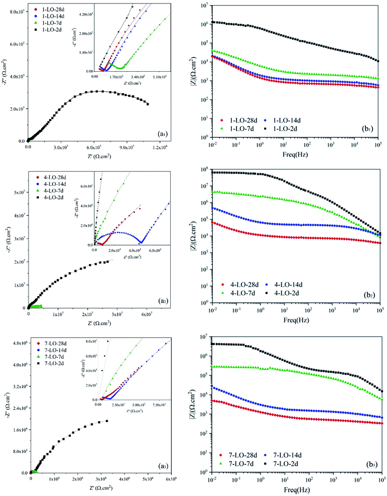 | ||
| Fig. 13 (a) Nyquist and (b) Bode plots of scratched coating specimens loaded with different concentrations of LO microcapsules after various exposure times to 3.5 wt% NaCl. | ||
| Sample | Rs (Ω cm2) | Qc | Rc (kΩ cm2) | Qdl | Rct (kΩ cm2) | W (mΩ s5 cm−2) | η (%) | |||
|---|---|---|---|---|---|---|---|---|---|---|
| Y0 (μsn Ω−1 cm−2) | n | Y0 (μsn Ω−1 cm−2) | n | |||||||
| 1-LO | 2d | 102.9 | 0.0069 | 0.87 | 29.3 | 0.475 | 0.48 | 1210 | — | 95.30 |
| 7d | 113.5 | 0.175 | 0.8 | 2.06 | 72.4 | 0.8 | 66.45 | — | 93.69 | |
| 14d | 128.6 | 4.24 | 0.52 | 1.12 | 233 | 0.71 | 50.83 | — | 94.13 | |
| 28d | 114.1 | 2.1 | 0.48 | 0.48 | 277 | 0.72 | 41.31 | — | 92.01 | |
| 4-LO | 2d | 152.3 | 0.00077 | 0.93 | 246.3 | 0.034 | 0.38 | 39![[thin space (1/6-em)]](https://www.rsc.org/images/entities/char_2009.gif) 618 618 |
— | 99.84 |
| 7d | 112.4 | 0.0059 | 0.78 | 349.1 | 0.43 | 0.31 | 3511 | — | 99.88 | |
| 14d | 125.1 | 0.014 | 0.64 | 46.2 | 10.2 | 0.66 | 1134 | — | 99.73 | |
| 28d | 116.8 | 0.59 | 0.52 | 7.9 | 80.7 | 0.67 | 614 | — | 99.75 | |
| 7-LO | 2d | 141.7 | 0.0022 | 0.89 | 8971 | 0.015 | 0.8 | 16![[thin space (1/6-em)]](https://www.rsc.org/images/entities/char_2009.gif) 610 610 |
— | 99.19 |
| 7d | 146.3 | 0.014 | 0.72 | 88.9 | 0.54 | 0.56 | 189 | — | 97.78 | |
| 14d | 119.7 | 1.55 | 0.49 | 1.48 | 206.1 | 0.57 | 128 | — | 97.53 | |
| 28d | 155.2 | 1.67 | 0.51 | 0.49 | 312.8 | 0.53 | 1.73 | 0.42 | 75.24 | |
Increasing the capsule percentage to 4 wt% led to better corrosion performance. However, at 7 wt% LO microcapsules, compared to 4 wt%, an efficiency drop was observed, which as described earlier, is caused by the problems originated from agglomeration of the microcapsules. Protection efficiency is calculated based on the corresponding exposure time for the capsule-free polyurethane. No matter how much capsules were embedded in the coating, still a drastic drop of the Rct was witnessed after 28 days of exposure and is expected to experience even more reduction with higher exposure times. Nevertheless, the protection efficiency for the optimum percentage of the LO capsules was close to 99% which guarantees an outstanding effectiveness of linseed oil as the self-healing agent. This is mainly because after the scratch is sealed by the polymerization reaction of linseed oil, the polyurethane would much likely act as an intact coating. Bode plot also shows a great efficiency as the |Z|0.01Hz value increased from 3.9 to 69.3 kΩ cm−2 for 4 wt% LO capsule embedded coating after 28 days of exposure.
Impedance spectra for the application of LO capsules loaded with SDS as the corrosion inhibitor in the polyurethane coating is shown in Fig. 14. A great corrosion inhibition efficiency was witnessed for the LO/SDS microcapsules. Although after 28 days of exposure, a drastic decrease was observed for each of the contents, the results show an obvious improvement compared to the neat samples. Based on the figure, the optimum concentration of capsules in the coating was 4 wt% since |Z|0.01Hz value increased from 3.9 to 343 kΩ cm−2 for 4 wt% LO/SDS capsule embedded coating after 28 days of exposure. The EIS results for the LO/SDS capsules are fitted using the same EEC's as for the LO capsules and are presented in Table 4. For the 1 and 7 wt% contents a Warburg impedance was appeared, which shows the concentration gradient of the aggressive ions from the electrolyte towards the surface. In this table, ηi is presented as the corrosion inhibition efficiency compared to the LO capsules. The results show a great effectiveness even compared to the linseed oil microcapsules, which is directly related to the inhibition mechanism of SDS.
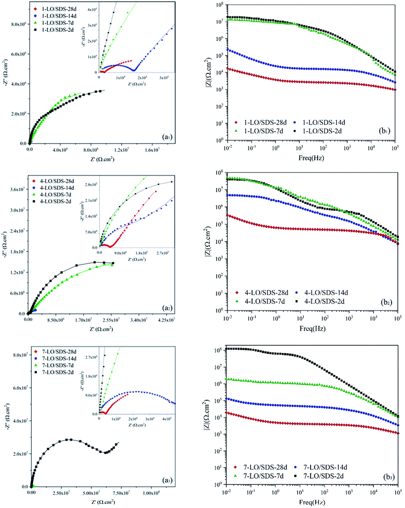 | ||
| Fig. 14 (a) Nyquist and (b) Bode plots of scratched coating specimens loaded with different concentrations of LO/SDS microcapsules after various exposure times to 3.5 wt% NaCl. | ||
| Sample | Rs (Ω cm2) | Qc | Rc (kΩ cm2) | Qdl | Rct (kΩ cm2) | W (mΩ s5 cm−2) | η (%) | ηi (%) | |||
|---|---|---|---|---|---|---|---|---|---|---|---|
| Y0 (μsn Ω−1 cm−2) | n | Y0 (μsn Ω−1 cm−2) | n | ||||||||
| 1-LO/SDS | 2d | 108.3 | 0.00054 | 0.89 | 2690 | 0.0292 | 0.58 | 16![[thin space (1/6-em)]](https://www.rsc.org/images/entities/char_2009.gif) 440 440 |
— | 99.65 | 92.63 |
| 7d | 111.5 | 0.0071 | 0.78 | 62.3 | 0.0743 | 0.51 | 15![[thin space (1/6-em)]](https://www.rsc.org/images/entities/char_2009.gif) 800 800 |
— | 99.97 | 99.57 | |
| 14d | 143.6 | 0.0054 | 0.67 | 16.2 | 24.9 | 0.66 | 514 | — | 99.42 | 90.11 | |
| 28d | 161.8 | 0.75 | 0.52 | 2.61 | 198.4 | 0.61 | 17.68 | 0.48 | 96.03 | 50.39 | |
| 4-LO/SDS | 2d | 121.6 | 0.00027 | 0.92 | 651 | 0.017 | 0.79 | 41![[thin space (1/6-em)]](https://www.rsc.org/images/entities/char_2009.gif) 150 150 |
— | 99.86 | 10.75 |
| 7d | 128.4 | 0.0022 | 0.81 | 1140 | 0.023 | 0.58 | 59![[thin space (1/6-em)]](https://www.rsc.org/images/entities/char_2009.gif) 120 120 |
— | 99.99 | 94.06 | |
| 14d | 115.8 | 0.0049 | 0.76 | 219 | 0.11 | 0.58 | 44![[thin space (1/6-em)]](https://www.rsc.org/images/entities/char_2009.gif) 310 310 |
— | 99.99 | 97.44 | |
| 28d | 147.4 | 0.015 | 0.62 | 47.1 | 16.7 | 0.56 | 6292 | — | 99.97 | 90.24 | |
| 7-LO/SDS | 2d | 142.3 | 0.0037 | 0.91 | 136.1 | 0.149 | 0.62 | 7491 | — | 99.65 | 57.28 |
| 7d | 151.6 | 0.0056 | 0.77 | 552 | 3.88 | 0.42 | 1615 | — | 99.74 | 88.29 | |
| 14d | 111.7 | 0.23 | 0.52 | 50.3 | 86.1 | 0.63 | 285 | — | 99.14 | 59.39 | |
| 28d | 136.8 | 0.52 | 0.54 | 4.01 | 229.8 | 0.62 | 32.1 | 0.77 | 89.79 | 58.7 | |
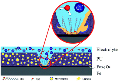
SDS is an organic compound that performs through an adsorption mechanism. As the result of the electrostatic forces from the surface, the negatively charged groups of the SDS will tend to move towards the surface to donate lone pair electrons to the vacant d-orbital of iron metal. This interaction results in adsorption of the molecules by the polar head, which could lead to corrosion inhibition in three ways.48,49 The first is that as the result of the interaction the possible diffused aqueous electrolyte would have to go through a lot of struggles to pass the hydrophobic tales of the adsorbed molecules.39 The second is that there is a great chance for the long hydrophobic chain to relax on the metal and make the surface inaccessible for the corrosive medium by covering the active areas.16,50–52 Another way for corrosion inhibition by the SDS lies in the fact that after the adsorption on the surface, the metal becomes more stable as the active spots are now stabilized though the covalent bond with the organic molecules.53–55 As the result, less electrostatic force would be sensed by the aggressive agents such as Cl− to move towards the surface and therefore better corrosion inhibition efficiency would be expected. The |Z|0.01Hz value change is presented in Fig. 15. According to the figure, the healing effect of SDS after 28 days of exposure, specially in 4 wt%, is obviously recognizable as there is an almost 81% change in the |Z|0.01Hz value of the coatings embedded with LO/SDS capsules compared to the ones with LO.
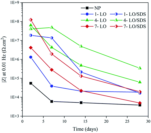 | ||
| Fig. 15 |Z|0.01Hz value change for different concentrations of microcapsule after various exposure times to 3.5 wt% NaCl. | ||
A simplified schematic of the inhibition mechanism by SDS loaded microcapsules is presented in Fig. 16, which shows the hydrophobic-based mechanism of SDS in adsorption process.
3.4 Self-healing evaluation
To investigate the self-healing process in the LO/SDS microcapsule embedded coating, the morphology of the scratched area after 24 h exposure to air was examined by means of the FE-SEM and the micrographs are shown in Fig. 17. For the purpose of comparison, the coating was loaded with the 4 wt% LO/SDS capsules as the optimum concentration. As it can be seen, in the presence of the microcapsules, the artificial scratch is filled with the healing agents that went free after the rupture of the capsule walls. A complex bulk of polymerized linseed oil was observed which restores the barrier property of the coating.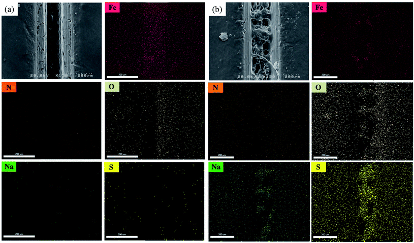 | ||
| Fig. 17 FE-SEM micrograph and elemental mapping of Fe, N, O, Na and S of scratched surface for (a) neat polyurethane and (b) 4 wt% LO/SDS coating after 24 h of exposure to air. | ||
To confirm the presence of SDS as the second healing mechanism for the corrosion inhibition of steel, EDS mapping was employed and the outcomes are illustrated in Fig. 17a and b. An appropriate distribution of S and Na is observed for capsule embedded sample. In addition, the depletion of S around the scratched part of LO/SDS sample shows the successful release of microcapsules load to the damaged section. The chemical composition of Fe, C, O, S and Na elements are reported in Fig. 18. 3.8% S and 3% Na was recorded for the LO/SDS capsules embedded system, ensuring the presence of SDS along the scratch line. The outcomes of this experiment was in full agreement with electrochemical analysis, which confirms the self-healing ability of the polyurethane coating loaded with the LO/SDS microcapsules.
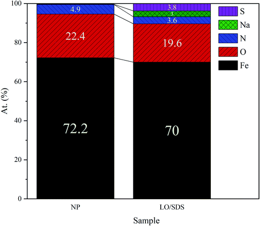 | ||
| Fig. 18 Elemental composition of the scratched surface for neat polyurethane and 4 wt% LO/SDS coating after 24 h of exposure to air. | ||
4. Conclusion
Two kinds of microcapsules, with and without SDS as the corrosion inhibitor were separately incorporated into polyurethane in order to obtain self-healing coating. FT-IR and TG analysis confirmed the successful encapsulation of SDS.• Synthesized microcapsules and in particular the ones with LO/SDS showed a mildly rough surface on their shell which resulted in an appropriate entanglement between the capsules and the polymer bulk. Therefore, the water absorption rate was lower than the neat coating since a good additive-matrix interfacial compatibility was achieved and it was further decreased by increasing the capsule concentration.
• A negative effect was observed on the adherence of the coating on steel specimens as the adhesion strength was reduced after the addition of microcapsules, which is probably because of some metal/coating interface accumulations that leads to less available areas on the steel surface.
• Open circuit potential was monitored for 28 days and approximately +200 mV potential shift was observed for samples with 4 wt% LO/SDS microcapsule.
• Potentiodynamic results showed a minimum of 83% efficiency for each percentage of LO/SDS capsules. The best performance was observed for 4 wt% LOS/SDS microcapsules with 88.1% inhibition efficiency.
• In the EIS measurements, although prolonging the exposure time reduced the protection efficiency, both microcapsules demonstrated an outstanding self-healing effectiveness. This is reasonable since based on the FE-SEM images of the scratch, the release of healing agents from microcapsules could effectively seal the defect and therefore push the coating to act as a semi-intact polyurethane.
• According to EIS results, presence of SDS as the corrosion inhibitor in the released linseed oil increased the inhibition efficiency by more than 90% for 4 wt%, compared to the single LO capsules. It was suggested that the corrosion inhibition efficiency of SDS is through adsorbing on the surface by the polar head and blocking the accessible area and simultaneously stabilizing the active spots on the metal. EDS mapping was also employed to verify the successful release and distribution of the SDS to the scratch. All the data were in a good agreement with each other and confirmed the self-healing capability of polyurethane incorporated with LO/SDS microcapsules.
Conflicts of interest
There are no conflicts to declare.References
- G. H. Koch, Historic Congressional study: Corrosion costs and preventive strategies in the United States, 2002 Search PubMed
.
- R. C. Newman and K. Sieradzki, Science, 1994, 263, 1708–1710 CrossRef CAS PubMed
.
- D. Y. Zhu, M. Z. Rong and M. Q. Zhang, Prog. Polym. Sci., 2015, 49, 175–220 CrossRef
.
- M. Huang, H. Zhang and J. Yang, Corros. Sci., 2012, 65, 561–566 CrossRef CAS
.
- F. Zhang, P. Ju, M. Pan, D. Zhang, Y. Huang, G. Li and X. Li, Corros. Sci., 2018, 144, 74–88 CrossRef CAS
.
- L. Wang, C. Zhang, H. Xie, W. Sun, X. Chen, X. Wang, Z. Yang and G. Liu, Corros. Sci., 2015, 90, 296–304 CrossRef CAS
.
- K. Wu, T. Gui, J. Dong, J. Luo and R. Liu, Prog. Org. Coat., 2022, 162, 106592 CrossRef CAS
.
- K. Wu, Z. Wei, Y. Dong, Y. He, H. Liu, G. Sun and J. Luo, Colloids Surf., A, 2022, 642, 128660 CrossRef CAS
.
- M. Samadzadeh, S. H. Boura, M. Peikari, S. Kasiriha and A. Ashrafi, Prog. Org. Coat., 2010, 68, 159–164 CrossRef CAS
.
- T. Matsuda, K. B. Kashi, K. Fushimi and V. J. Gelling, Corros. Sci., 2019, 148, 188–197 CrossRef CAS
.
- T. Nesterova, K. Dam-Johansen, L. T. Pedersen and S. Kiil, Prog. Org. Coat., 2012, 75, 309–318 CrossRef CAS
.
- M. Plawecka, D. Snihirova, B. Martins, K. Szczepanowicz, P. Warszynski and M. Montemor, Electrochim. Acta, 2014, 140, 282–293 CrossRef CAS
.
- T. H. Lee, Y. K. Song, S. H. Park, Y. I. Park, S. M. Noh and J. C. Kim, Appl. Surf. Sci., 2018, 434, 1327–1335 CrossRef CAS
.
- Y. Zhao, W. Zhang, L.-p. Liao, S.-j. Wang and W.-j. Li, Appl. Surf. Sci., 2012, 258, 1915–1918 CrossRef CAS
.
- W. Fan, H. Wang, C. Wang, Z. Liu, Y. Zhu and K. Li, Appl. Surf. Sci., 2020, 521, 146417 CrossRef CAS
.
- M. Izadi, T. Shahrabi and B. Ramezanzadeh, Appl. Surf. Sci., 2018, 440, 491–505 CrossRef CAS
.
- S. Amiri, in Micro-and Nano-containers for Smart Applications, Springer, 2022, pp. 213–241 Search PubMed
.
- N. Farshchi, in Micro-and Nano-containers for Smart Applications, Springer, 2022, pp. 197–211 Search PubMed
.
- S. H. Boura, M. Peikari, A. Ashrafi and M. Samadzadeh, Prog. Org. Coat., 2012, 75, 292–300 CrossRef
.
- M. Samadzadeh, S. H. Boura, M. Peikari, A. Ashrafi and M. Kasiriha, Prog. Org. Coat., 2011, 70, 383–387 CrossRef CAS
.
- S. Ataei, S. N. Khorasani, R. Torkaman, R. E. Neisiany and M. S. Koochaki, Prog. Org. Coat., 2018, 120, 160–166 CrossRef CAS
.
- L. Liao, W. Zhang, Y. Xin, H. Wang, Y. Zhao and W. Li, Chin. Sci. Bull., 2011, 56, 439–443 CrossRef CAS
.
- V. V. Gite, P. D. Tatiya, R. J. Marathe, P. P. Mahulikar and D. G. Hundiwale, Prog. Org. Coat., 2015, 83, 11–18 CrossRef CAS
.
- F. Kuang, T. Shi, J. Wang and F. Jia, J. Solid State Electrochem., 2009, 13, 1729–1735 CrossRef CAS
.
- P. D. Tatiya, R. K. Hedaoo, P. P. Mahulikar and V. V. Gite, Ind. Eng. Chem. Res., 2013, 52, 1562–1570 CrossRef CAS
.
- L. M. Meng, Y. C. Yuan, M. Z. Rong and M. Q. Zhang, J. Mater. Chem., 2010, 20, 6030–6038 RSC
.
- H. Pulikkalparambil, S. Siengchin and J. Parameswaranpillai, Nano-Struct. Nano-Objects, 2018, 16, 381–395 CrossRef CAS
.
- P. Vijayan and M. AlMaadeed, eXPRESS Polym. Lett., 2016, 10(6), 506–524 CrossRef
.
- E. Koh, N.-K. Kim, J. Shin and Y.-W. Kim, RSC Adv., 2014, 4, 16214–16223 RSC
.
- D. Saihi, I. Vroman, S. Giraud and S. Bourbigot, React. Funct. Polym., 2006, 66, 1118–1125 CrossRef CAS
.
- Q. Z. Sinuo Lang, Prog. Org. Coat., 2017, 105, 99–110 CrossRef
.
- C. Suryanarayana, K. C. Rao and D. Kumar, Prog. Org. Coat., 2008, 63, 72–78 CrossRef CAS
.
- J. Li, S. Yang, Y. Muhammad, M. Sahibzada, Z. Zhu, T. Liu and S. Liao, Constr. Build. Mater., 2020, 246, 118452 CrossRef CAS
.
- M. Behzadnasab, M. Esfandeh, S. Mirabedini, M. Zohuriaan-Mehr and R. Farnood, Colloids Surf., A, 2014, 457, 16–26 CrossRef CAS
.
- J. Mallégol, J. Lemaire and J.-L. Gardette, Prog. Org. Coat., 2000, 39, 107–113 CrossRef
.
- S. S. T. Siva, Prog. Org. Coat., 2015, 82, 57–67 CrossRef
.
- R. Najjar, M. Akbari, A. Mirmohseni and M. Hosseini, J. Taiwan Inst. Chem. Eng., 2018, 93, 1–10 CrossRef CAS
.
- M. Mahmoudian, E. Nozad, M. G. Kochameshki and M. Enayati, Prog. Org. Coat., 2018, 120, 167–178 CrossRef CAS
.
- S. Javadian, A. Yousefi and J. Neshati, Appl. Surf. Sci., 2013, 285, 674–681 CrossRef CAS
.
- S. Lang and Q. Zhou, Prog. Org. Coat., 2017, 105, 99–110 CrossRef CAS
.
- S. U. Göksenin Kurt Çömlekçi, Prog. Org. Coat., 2019, 129, 292–299 CrossRef
.
- M. Mosiewicki, M. I. Aranguren and J. Borrajo, J. Appl. Polym. Sci., 2005, 97, 825–836 CrossRef CAS
.
- H. Lun, J. Ouyang and H. Yang, Phys. Chem. Miner., 2014, 41, 281–288 CrossRef CAS
.
- A. El-Etre, M. Abdallah and Z. El-Tantawy, Corros. Sci., 2005, 47, 385–395 CrossRef CAS
.
- I. Azamian, S. Allahkaram, M. Johari and F. Teymouri, RSC Adv., 2022, 12, 3524–3541 RSC
.
- C. M. Fernandes, V. G. Pina, L. X. Alvarez, A. C. F. de Albuquerque, F. M. dos Santos Júnior, A. M. Barrios, J. A. Velasco and E. A. Ponzio, Colloids Surf., A, 2020, 124857 CrossRef
.
- B. M. Anderson and D. W. Ma, Lipids Health Dis., 2009, 8, 1–20 CrossRef PubMed
.
- M. Johari, S. Allahkaram, F. Teymouri, I. Azamian and M. Shekarchi, Constr. Build. Mater., 2021, 308, 125037 CrossRef CAS
.
- F. Teymouri, S. R. Allahkaram, M. Shekarchi, I. Azamian and M. Johari, Constr. Build. Mater., 2021, 296, 123702 CrossRef CAS
.
- J. Falcón, F. Batista and I. Aoki, Electrochim. Acta, 2014, 124, 109–118 CrossRef
.
- R. Raj, Y. Morozov, L. Calado, M. Taryba, R. Kahraman, A. Shakoor and M. Montemor, Electrochim. Acta, 2019, 319, 801–812 CAS
.
- D. Snihirova, S. V. Lamaka, M. M. Cardoso, J. A. Condeço, H. E. Ferreira and M. de Fatima Montemor, Electrochim. Acta, 2014, 145, 123–131 CrossRef CAS
.
- J. Dong, W. Pan, J. Luo and R. Liu, Electrochim. Acta, 2020, 364, 137299 CrossRef CAS
.
- F. Teymouri, I. Samiei, S. R. Allahkaram, I. Azamian, M. Johari and M. Shekarchi, J. Mol. Liq., 2022, 119060 CrossRef CAS
.
- N. P. Tavandashti, M. Ghorbani, A. Shojaei, J. Mol, H. Terryn, K. Baert and Y. Gonzalez-Garcia, Corros. Sci., 2016, 112, 138–149 CrossRef
.
| This journal is © The Royal Society of Chemistry 2022 |

