
 Open Access Article
 This Open Access Article is licensed under a Creative Commons Attribution-Non Commercial 3.0 Unported Licence
One-step chemical vapor deposition fabrication of Ni@NiO@graphite nanoparticles for the oxygen evolution reaction of water splitting
Meijun Yanga,
Hongyu Zhua,
Yingqiu Zhengab,
Chitengfei Zhang *ab,
Guoqiang Luoab,
Qingfang Xua,
Qizhong Lia,
Song Zhanga,
Takashi Gotoa and
Rong Tuabc
*ab,
Guoqiang Luoab,
Qingfang Xua,
Qizhong Lia,
Song Zhanga,
Takashi Gotoa and
Rong Tuabc
aState Key Laboratory of Advanced Technology for Materials Synthesis and Processing, Wuhan University of Technology, Wuhan 430070, China. E-mail: zctf@foxmail.com
bChaozhou Branch of Chemistry and Chemical Engineering Guangdong Laboratory, Chaozhou 521000, China
cWuhan University of Technology Advanced Engineering Technology Research Institute of Zhongshan City, Zhongshan 528400, China
First published on 5th April 2022
Abstract
NiO combined with conductive materials is a practicable way to improve its catalytic property for the oxygen evolution reaction (OER) by enhancing its electrical conductivity. Herein, Ni@NiO@graphite nanoparticles less than 20 nm in average diameter were synthesized by a one-step chemical vapor deposition process. Due to the deliberately controlled lack of oxygen, Ni particles and carbon clusters decomposed from NiCp2 precursors were oxidized incompletely and formed Ni@NiO core–shell nanoparticles coated by a graphite layer. The thickness of the graphite layer and the content of Ni were controlled by varying deposition temperature. The electrochemical activity towards the oxygen evolution reaction was assessed within alkaline media. Compared with commercial NiO powder, the Ni@NiO@graphite nanoparticles with the unique core–shell microstructure exhibit excellent OER performance, i.e., an overpotential of 330 mV (vs. RHE) at 10 mA cm−2 and a Tafel slope of 49 mV dec−1, due to the improved electrical conductivity and more active sites. This work provides a facile and rapid strategy to produce nanoparticles with unique microstructures as highly active electrocatalysts for the OER.
1. Introduction
Compared with biomass hydrogen production, hydrocarbon pyrolysis and thermochemical water splitting, electrochemical hydrogen evolution has received extensive attention and possesses several advantages such as a simple process, no carbon pollution, and high product purity.1,2 The oxygen evolution reaction (OER) (2H2O = O2 + 4H+ + 4e−), the half reaction of water splitting, involves the transfer of four electrons and requires a high overpotential (1.23 V), which greatly limits its overall efficiency.3,4 Therefore, the exploration of highly efficient OER electrocatalysts is a key factor in increasing the efficiency of water splitting. At present, noble metal catalysts exhibit excellent performance in OER.5–7 However, their scarcity and high price have seriously hindered their utilization on a commercial scale.8,9 It has been found that other materials such as transition metals also exhibit excellent OER activity in alkaline electrolytes.10,11 Among these materials, NiO-based catalysts have received extensive attention as replacements for Ru- and Ir-based materials due to their high abundance, low cost and lower overpotential.12 Sai et al. reported plasma-activated NiO nanosheets that surpassed the electrocatalytic performance of the benchmark RuO2.13 Nevertheless, further application of NiO-based electrocatalytic materials is greatly limited by their low conductivity.14,15 Combining NiO catalysts with conductive materials, such as carbon-based materials or nickel, is a practicable way to enhance electrical conductivity and improve OER activity.16,17 Srinivasa et al. synthesized Ni/NiO nanocomposites and increased the current density by 134% over that of bare NiO.18 Zhang et al. introduced ordered mesoporous carbon (OMC) into NiO/CoO nanocomposites to improve conductivity, which enables NiCo2O3@OMC to exhibit a low overpotential of 281 mV at 10 mA cm−2.19 Moreover, the formation of multicomponent heterojunction structures is also beneficial to the improvement of electrocatalytic performance.20,21Currently, introducing carbon and/or nickel into NiO catalysts generally involves multiple synthetic steps, e.g., hydrothermal and nitrogen plasma activation,13 roasting and annealing.22 However, metal–organic chemical vapor deposition (MOCVD) makes it possible to controllably form graphene or graphite nanolayers on the powder and/or grain boundaries in the films due to the decomposition of hydrocarbon precursors.23,24 So far, many metallic catalysts containing carbon have been synthesized by MOCVD, such as STFN/CNTs,25 FeCoNi@N-CNTs26 and defect-rich MWCNTs/CoFe,27 showing excellent catalytic properties. However, it has been difficult to obtain an oxide catalyst containing carbon through a one-step CVD approach. In this work, we propose a facile MOCVD process to synthesize graphite-coated Ni@NiO nanoparticles in one step. The thickness and structure of the carbon layer and the content of Ni are controlled by adjusting the deposition temperature. In addition, the growth mechanism and OER performance of the nanoparticles with their unique microstructure are discussed. It is demonstrated that the Ni@NiO@graphite nanoparticles have a more positive effect on OER performance than commercial NiO and IrO2.
2. Experimental
2.1 Preparation of NiO nanoparticles
The NiO nanoparticles were synthesized using a homemade CVD system with a vertical tube furnace (Tianjin Zhonghuan Electric Furnace Co., Ltd) and a rotary vacuum pump. Bis(cyclopentadienyl)nickel(II) (NiCp2, Shanghai Aladdin Biochemical Technology Co., 98%) powder was loaded in a stainless steel tank and evaporated at 120 °C and then transported to the reaction zone (deposition temperature Tdep = 400–800 °C) using Ar as a carrier gas (99.999%, Chaozhou Dafeng) with a flow rate of 200 sccm. Diluted oxygen (20% O2 in N2, 99.999%, Chaozhou Dafeng) with a flow rate of 500 sccm was introduced into the reaction chamber to oxidize NiCp2. The total pressure was maintained at 10 torr, and the deposition time was fixed at 2 h.2.2 Characterization
The crystal phase of the NiO powder was identified by X-ray diffraction (XRD, Rigaku, Tokyo, Japan, CuKα) and Raman spectroscopy (Renishaw in Via, 2UM965). The morphology of the samples was studied by scanning electron microscopy (SEM, TESCAN MIRA LMS, 5 kV) and high-resolution transmission electron microscopy (HR-TEM, FEI Tecnai F20, 200 kV). The chemical states were studied using X-ray photoelectron spectroscopy (XPS, Thermo Scientific K-Alpha, Al-Kα hν = 1486.6 eV). Charge correction of all the peaks used C 1s = 284.80 eV binding energy as the energy standard.2.3 Electrocatalytic measurement
All electrochemical measurements were performed using an electrochemical workstation (Metrohm Autolab, PGSTAT302N, Netherlands) with a three-electrode system at room temperature. The catalytic inks were prepared by mixing a 5 mg powder sample and 30 μL Nafion dispersed in the mixture of 600 μL ethanol (98%, Sinopharm Chemical Reagent) and 600 μL ultrapure water. Then, the inks were deposited on a freshly polished glassy carbon electrode (3 mm in diameter) to form the working electrodes; graphite was used as the counter electrode and a saturated Hg/HgO electrode was used as the reference electrode. The electrochemical OER performances of the samples as well as commercial NiO (Beijing Innochem Technology Co., 99.9%) and IrO2 (Shanghai Aladdin Biochemical Technology Co., 99.9%) were measured in 1 M KOH electrolyte by linear sweep voltammetry (LSV). LSV measurements were carried out at a scan rate (rs) of 2 mV s−1 in a potential range of 0.18–0.78 V (vs. SCE). From the LSV curve, the Tafel slope was derived and fitted according to the Tafel equation η = a + b![[thin space (1/6-em)]](https://www.rsc.org/images/entities/char_2009.gif) logj, where η refers to the overpotential, j represents the measured current density, b is the Tafel slope and a is a constant. The double-layer capacitance (Cdl) of the different catalysts obtained was measured by cyclic voltammetry (CV) at different scanning rates of 10, 20, 30, 40, 50 and 60 mV s−1 in the non-faradaic potential region (0.3 to 0.4 V). Electrochemical impedance spectroscopy (EIS) was also performed to obtain the OER kinetics. The frequency ranged from 0.1 Hz to 100 kHz, and the corresponding amplitude was 5 mV. All of the potentials in this work were converted to that vs. the reversible hydrogen electrode (RHE), which were calculated according to the Nernst equation ERHE (iR compensation) = EHg/HgO + 0.098 + 0.059 × pH, and the overpotential η = ERHE − 1.23 V.
logj, where η refers to the overpotential, j represents the measured current density, b is the Tafel slope and a is a constant. The double-layer capacitance (Cdl) of the different catalysts obtained was measured by cyclic voltammetry (CV) at different scanning rates of 10, 20, 30, 40, 50 and 60 mV s−1 in the non-faradaic potential region (0.3 to 0.4 V). Electrochemical impedance spectroscopy (EIS) was also performed to obtain the OER kinetics. The frequency ranged from 0.1 Hz to 100 kHz, and the corresponding amplitude was 5 mV. All of the potentials in this work were converted to that vs. the reversible hydrogen electrode (RHE), which were calculated according to the Nernst equation ERHE (iR compensation) = EHg/HgO + 0.098 + 0.059 × pH, and the overpotential η = ERHE − 1.23 V.
3. Results and discussion
3.1 Characterization of the crystal phase and microstructure
Fig. 1a shows the XRD patterns of the nickel oxide nanoparticles prepared at Tdep = 400, 500, 600, 700 and 800 °C. The five main diffraction peaks at 37.33°, 43.38°, 63.02°, 75.59° and 79.60° correspond to the planes of (111), (200), (220), (311) and (222) of cubic NiO (PDF# 73-1519). The peak of cubic Ni (PDF# 70-0989) is identified in the samples collected at 600 °C. At Tdep = 700 °C, the peak of Ni is significantly enhanced and that of hexagonal graphite (PDF# 75-1621) appears. Furthermore, when Tdep rises to 800 °C, the relative intensity of Ni increases further, suggesting that the content of Ni is positively correlated with the deposition temperature. The broadened diffraction peaks of NiO indicate that the grain size of NiO nanoparticles is very small.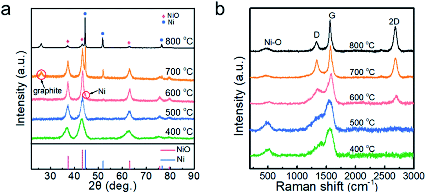 | ||
| Fig. 1 (a) XRD patterns and (b) Raman spectra of the powder samples prepared at 400, 500, 600, 700 and 800 °C. | ||
The Raman spectra are presented in Fig. 1b in order to identify the phase of carbon in the nanoparticles. At Tdep = 400 and 500 °C, the asymmetric broad peak was located at ∼1560 cm−1, but a 2D peak of carbon was not observed, demonstrating the formation of amorphous carbon.28 At Tdep = 600 °C, a weak 2D peak appeared, indicating that the carbon tended to graphitization. Thereafter, as the deposition temperature increased from 700 to 800 °C, the intensity ratio of D to G decreased from 0.85 to 0.43 and the value of I2D/IG increased, suggesting that the higher temperature promoted the graphitization of the carbon in the samples. The formation of crystallized graphite may have been also relevant to the catalytic effect of Ni nanoparticles.29 In addition, the peak at 487 cm−1 originating from the Ni–O bond30 is clearly observed in the samples prepared at 400–800 °C.
The XPS analyses of the powder samples prepared at different temperatures are shown in Fig. 2, and the survey XPS spectrum presented in Fig. 2a confirms the existence of Ni, O, and C in the samples. Ni 2p spectra are shown in Fig. 2b, exhibiting two group peaks of Ni 2p3/2 and Ni 2p1/2. It is shown that the multiple-split peaks of Ni 2p3/2 are located at 854.2 and 856.4 eV and a satellite peak is located at 860.9 eV for Ni2+.31 The multiple-split peaks of Ni 2p1/2 (872.1 and 874.9 eV) and the Ni 2p1/2 satellite peak (879.3 eV) are also observable, which is in good agreement with the characteristic peaks of Ni2+. When the deposition temperature rises to 800 °C, the two peaks of binding energy at 852.8 and 870.0 eV with a spin energy separation of 17.2 eV confirm the presence of Ni0 in the samples.14 When the deposition temperature is lower than 700 °C, the Ni0 peak is not observed in the XPS spectrum, which is inconsistent with the XRD patterns. Since the penetration depth of XPS is usually 0.5 to 3 nm for metallic materials,32 the NiO shell may shield the detection of the Ni core by XPS. According to the XPS spectra of C 1s (Fig. 2c) and O 1s (Fig. 2d), the peaks derived from the C–O![[double bond, length as m-dash]](https://www.rsc.org/images/entities/char_e001.gif) C bond and CO bond are relatively strong in the sample prepared at 400 °C, indicating that the sample contains more undecomposed hydrocarbons. The content of sp2 (CC) exceeded that of sp3 (C–C) with increasing deposition temperature, which indicates enhanced graphitization of the carbon layer.
C bond and CO bond are relatively strong in the sample prepared at 400 °C, indicating that the sample contains more undecomposed hydrocarbons. The content of sp2 (CC) exceeded that of sp3 (C–C) with increasing deposition temperature, which indicates enhanced graphitization of the carbon layer.
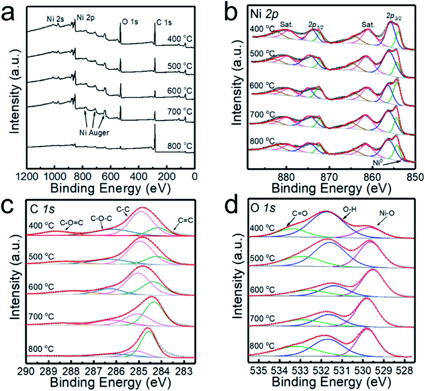 | ||
| Fig. 2 XPS spectra of the powders prepared at 400, 500, 600, 700 and 800 °C. (a) High-resolution survey, (b) Ni 2p, (c) C 1s and (d) O 1s. | ||
Fig. 3 shows the SEM images of the NiO nanoparticles. All the samples consist of spherical nanoparticles with a diameter less than 20 nm. To investigate the effect of temperature on particle size, more than 150 nanoparticles were measured, as shown in Fig. 3f. The average particle size increased from 12 to 16 nm with increasing temperature from 400 to 800 °C. Fig. 4 shows the TEM images of the samples prepared at 500 and 700 °C. At Tdep = 500 °C, NiO nanoparticles were wrapped by an amorphous carbon layer with a thickness of about 6.4 nm. At Tdep = 700 °C, the thickness of the carbon layer decreases to 1.2 nm and the HR-TEM image indicates that metallic Ni intimately contacted with the NiO phase, forming Ni–NiO interfaces through the heterostructure of the strongly interfaced Ni–NiO complexes.
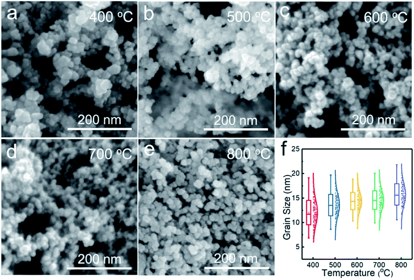 | ||
| Fig. 3 SEM images of the powder samples prepared at (a) 400, (b) 500, (c) 600, (d) 700 and (e) 800 °C. (f) Statistics of particle size with respect to deposition temperature. | ||
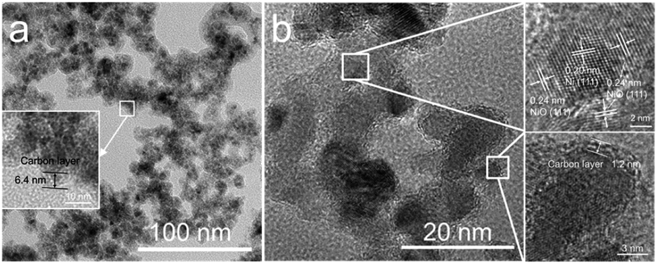 | ||
| Fig. 4 TEM images of the powder samples prepared at (a) 500 and (b) 700 °C. | ||
3.2 Formation mechanism
Based on the structural and morphological analysis of the products synthesized at different temperatures, the formation process of NiO@C and Ni@NiO@graphite nanoparticles is proposed, as shown in Fig. 5. NiCp2 powder is evaporated and transported by Ar gas to the deposition zone. Gaseous NiCp2 is thermally decomposed into nickel and hydrocarbon species. These molecular clusters aggregate together and form nickel nanoparticles due to their high surface activity and high surface adsorption during the collision process.33 Due to the final particle size of NiO being only slightly different, as shown in Fig. 3f, the growth rate of the nickel nanoparticles is almost independent of deposition temperature. Then, the nickel nanoparticles are oxidized to become NiO, and a part of the hydrocarbon transforms to form a carbon layer on the surface of the NiO nanoparticles. The oxidation degree of Ni and the crystallinity of carbon are dependent on the deposition temperature. According to the Ellingham diagram,34 with increasing temperature, the standard free energies of formation (ΔGf) of NiO and H2O increase but that of CO decreases, with crossover points around 400 and 600 °C, respectively. Therefore, at lower temperatures, the hydrocarbon hardly reacts with oxygen, resulting in most of the oxygen being able to fully oxidize Ni to form NiO nanoparticles, as well as a great deal of amorphous carbon on the surface. On the other hand, at a higher temperature, the large amount of hydrocarbon easily reacts with oxygen35 and consumes it, leading to only a small part of oxygen partially oxidizing Ni to form Ni@NiO core–shell nanoparticles, while carbon crystallizes to graphite due to the high temperature or catalysis of Ni. Furthermore, the CO concentration increases with increasing temperature,34 resulting in a reducing atmosphere to form Ni easily at 800 °C, as shown in Fig. 1a.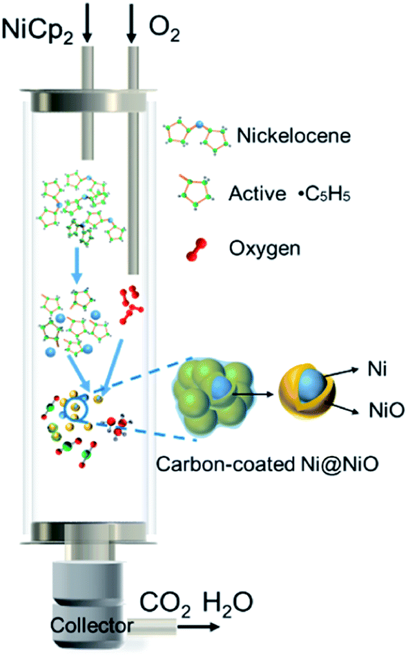 | ||
| Fig. 5 Schematic formation mechanism of the carbon-encapsulated Ni@NiO nanoparticles. | ||
3.3 Electrocatalytic OER study
The electrochemical performance of the electrocatalysts toward OER in alkaline medium was investigated by LSV. The anodic polarization curve is shown in Fig. 6a. The NiO electrodes generated at 400, 500, 600, 700 and 800 °C require overpotentials of 351, 342, 339, 330 and 340 mV versus RHE, respectively, to register a j = 10 mA cm−2 current density. The samples prepared at 700 °C give the optimal response towards OER. Compared with that of commercial NiO (403 mV), the overpotential of the sample has been significantly reduced, and when Tdep > 500 °C, the OER performance of the sample exceeds that of commercial IrO2 (350 mV). The samples synthesized at 700 and 800 °C display achievable current density, which is attributed to the enhanced conductivity due to the introduction of Ni and graphite. However, NiO is still the main component in the catalytic process,18 with excess Ni weakening the catalytic activity of the sample prepared at 800 °C.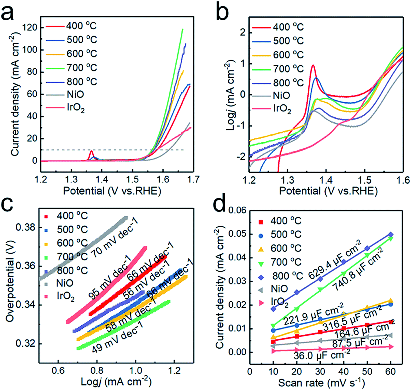 | ||
| Fig. 6 Electrocatalytic OER performance of the catalysts. (a) iR-corrected LSV profiles, (b) zoomed-in view of (a) in the log-scale, (c) corresponding Tafel slopes derived from the polarization curves, and (d) plots of capacitive currents as a function of scan rate. | ||
Fig. 6b plotted in the form of logj vs. potential highlights the oxidation peaks of different samples. This can be ascribed to the electro-oxidation of Ni(OH)2 to NiOOH, which proceeds as Ni(OH)2 + OH− → NiOOH + H2O + e− in alkaline electrolytes.36 With increasing deposition temperature, two redox peaks are observed, which could be attributed to the formation of γ-NiOOH and β-NiOOH. The surface of Ni and NiO would form different hydroxides, α-Ni(OH)2 and β-Ni(OH)2, in alkaline solution. Both polymorphs are readily electro-oxidized, giving rise to different NiOOH phases: α-Ni(OH)2 → γ-NiOOH and β-Ni(OH)2 → β-NiOOH, with the two processes occurring at different anode potentials.32 Therefore, the presence of the two redox peaks can be ascribed to two oxidation reactions.37 In addition, the oxidation of nickel requires a higher overpotential than that of NiO,38 so the oxidation peak shifts toward a higher overpotential at higher deposition temperature.
The catalytic kinetics of the electrodes were further investigated by Tafel plots. As shown in Fig. 6c, the Tafel slopes are 78, 66, 58, 49 and 56 mV dec−1 for the powder samples prepared at 400, 500, 600, 700 and 800 °C, respectively, displaying the best OER activity at Tdep = 700 °C. The Tafel slopes of the samples obtained at different deposition temperatures are lower than those of commercial IrO2 and NiO2. The excellent OER performance of the sample obtained at 700 °C is ascribed to the increased electrical conductivity and the appropriate ratio of Ni to NiO in the Ni/NiO heterostructure. The sample prepared at 800 °C exhibits poor OER performance due to the increase of grain size and the decrease of the electrochemically active area. To further confirm this conjecture, cyclic voltammetry (CV) scans were recorded and used to estimate catalytically active sites to assess the electrochemical active surface area (ECSA) calculated by ECSA = Cdl/Ce,21 where Ce is the unit area capacitance of the electrolyte; in KOH solution, Ce = 0.04 mF cm−2, and Cdl represents the double-layer capacitance, indicating the number of active sites. Cdl was obtained from the slope of the straight line, when the current density at the non-faradaic zones was plotted against the scan rate. As shown in Fig. 6d, the Cdl of the samples prepared at 400, 500, 600, 700 and 800 °C are 164.6, 221.9, 316.5, 740.8 and 629.4 μF cm−2, respectively. The highest Cdl of the graphite encapsulated Ni@NiO nanoparticles obtained at 700 °C demonstrates that the excellent electrocatalytic capacity of the sample is related to larger electrochemical active surface area.
To further verify the electrical conductivity of the samples, the electrochemical impedance spectroscopy technique (EIS) was carried out. The Nyquist plots obtained by the EIS test are shown in Fig. 7. The plots possess a semicircle with small diameters in the high-frequency range and an arc with large diameter in the low-frequency range.39 The equivalent circuit model shown in Fig. 7c contains two parallel components for surface impedance (Rsct and CPEs) and bulk impedance (Rbct and CPEb). Rs is the solution resistance, Rct the charge transfer resistance and CPE is a constant phase element. Rct is an important parameter for water splitting, with a lower Rct indicating a much faster electron transfer process between the electrode and the electrolyte interface and better electrocatalytic properties.40 The diameter of the small semicircles in the Nyquist plot corresponds to the Rsct. The Rsct decreased from 12.47 to 6.72, 2.81, 1.98 and 0.35 Ω with increasing deposition temperature and nickel content, which suggests more efficient charge transport in the sample prepared at 800 °C. It is indicated that the nickel core greatly enhances the electrical conductivity of the nanoparticles and promotes the OER catalytic activity.
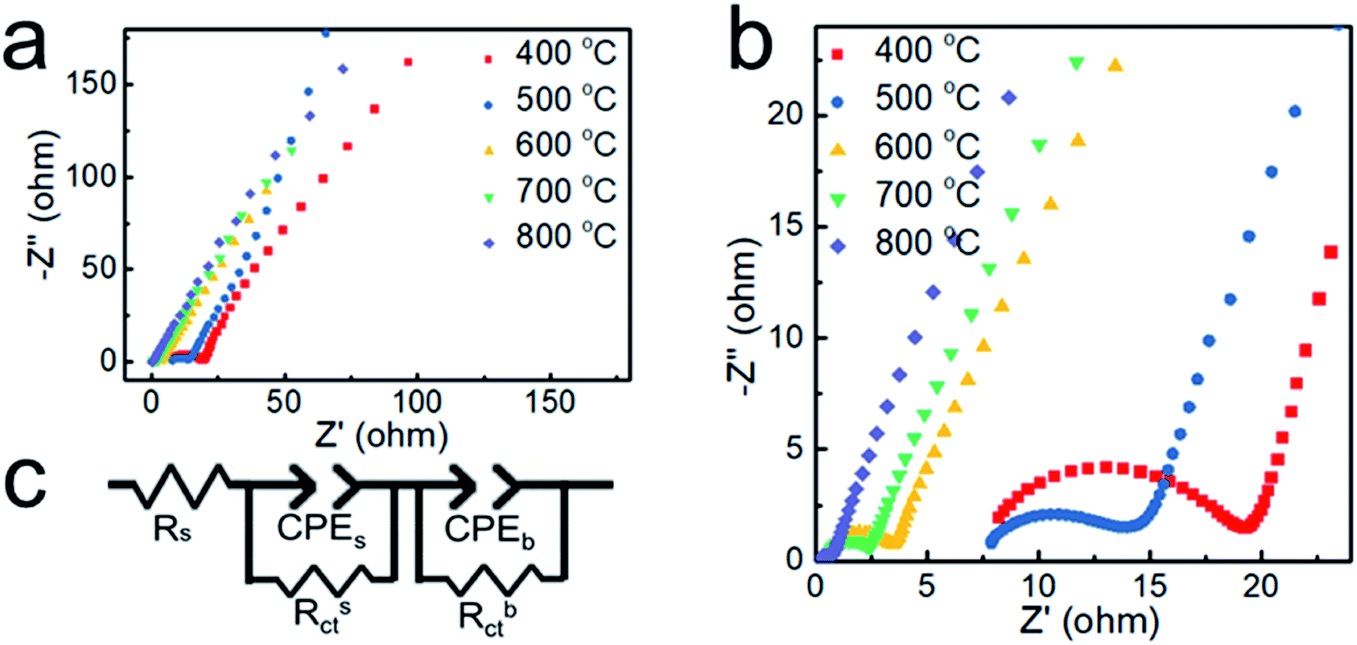 | ||
| Fig. 7 (a and b) Nyquist plots of the samples obtained at different temperatures. (c) The equivalent circuit model. | ||
Furthermore, the stability of Ni@NiO@graphite obtained at Tdep = 700 °C was tested by chronopotentiometry. As displayed in Fig. 8, the Ni@NiO@graphite electrocatalyst exhibits good electrochemical stability during 11 h at a constant current density of 10 mA cm−2 and the potential change was only 0.461% after the 11 h test.
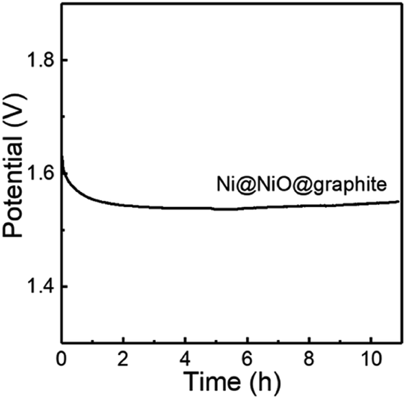 | ||
| Fig. 8 OER stability for the Ni@NiO@graphite obtained at Tdep = 700 °C. | ||
Fig. 9 compares the Tafel slope and overpotential of Ni@NiO@graphite with various NiO-based catalysts in the literature.11,13,15,21,32,41–48 The NiO catalysts combined with noble metal oxides show the best performance, i.e., the lowest Tafel slope and overpotential.41,46,47 The NiO/Ni/C systems have a Tafel slope of 40 to 100 mV dec−1 and an overpotential of 300 to 500 mV at a current density of 10 mA cm−2. The Ni@NiO@graphite electrocatalyst in this study is located at the left side of the group, slightly decreasing in overpotential and rapidly decreasing in Tafel slope with increasing Ni content. The overpotential and Tafel slope of Ni@NiO@graphite obtained at Tdep = 700 °C demonstrate the excellent catalytic performance next to the noble-metal-containing NiO system due to the appropriate content of crystallized graphite and Ni for the enhancement of electrical conductivity.
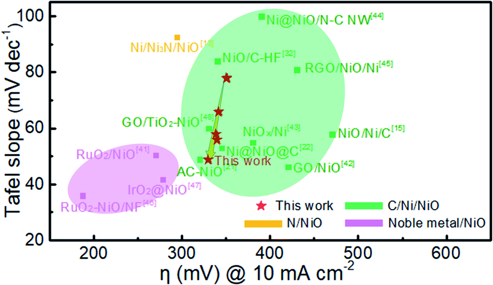 | ||
| Fig. 9 Comparison of Tafel slope and overpotential at a current density of 10 mA cm−2 in this work with other NiO-based catalysts in the literature. | ||
4. Conclusions
Graphite-encapsulated Ni@NiO nanoparticles less than 20 nm in diameter were synthesized by a facile one-step chemical vapor deposition process. With increasing deposition temperature, the nickel content in the powder sample increases and the carbon layer wrapped with NiO tends towards graphitization. The appropriate content of Ni in the Ni@NiO@graphite nanoparticles obtained at 700 °C effectively improves the electrocatalytic activity, exhibiting the best OER performance with the lowest overpotential of η10 = 330 mV in 1 M KOH electrolyte and a small Tafel slope of 49 mV dec−1. The MOCVD process developed in this work is simple and suitable for the large-scale synthesis of the powder, which provides a new idea for the preparation of graphite-encapsulated nanoparticles.Conflicts of interest
There are no conflicts to declare.Acknowledgements
This work was supported by the Key Area Research and Development Program of Guangdong Province (2020B010181001, 2019B121204001, 2021B0707050001), the China Postdoctoral Science Foundation (2021M692492), the Chaozhou Science and Technology Project (2019PT01), the Guangdong Major Project of Basic and Applied Basic Research (2021B0301030001), the Self-innovation Research Funding Project of Hanjiang Laboratory (HJL202012A001, HJL202012A002, HJL202012A003, HJL202104A001) and the Major Science and Technology Project in Zhongshan City, Guangdong Province (2019AG029). This work was also supported by the Joint Fund of the Ministry of Education for Pre-research of Equipment (6141A02022257), the Science Challenge Project (No. TZ2016001), the National Natural Science Foundation of China (No. 51861145306, 51872212 and 51972244), and the 111 Project (B13035). It was also supported by the International Science & Technology Cooperation Program of China (2018YFE0103600) and the Technological Innovation of Hubei Province, China (2019AAA030).References
- S. Shen, Z. Wang, Z. Lin, K. Song, Q. Zhang, F. Meng, L. Gu and W. Zhong, Adv. Mater., 2022, 2110631 CrossRef PubMed.
- T. Katsuki, Z. N. Zahran, K. Tanaka, T. Eo, E. A. Mohamed, Y. Tsubonouchi, M. R. Berber and M. Yagi, ACS Appl. Mater. Interfaces, 2021, 13, 39282–39290 CrossRef CAS PubMed.
- Z. N. Zahran, E. A. Mohamed, Y. Tsubonouchi, M. Ishizaki, T. Togashi, M. Kurihara, K. Saito, T. Yui and M. Yagi, Energy Environ. Sci., 2021, 14, 5358–5365 RSC.
- Z. Wang, S. Shen, Z. Lin, W. Tao, Q. Zhang, F. Meng, L. Gu and W. Zhong, Adv. Funct. Mater., 2022, 112832 Search PubMed.
- L. Tian, Z. Li, X. Xu and C. Zhang, J. Mater. Chem. A, 2021, 9, 13459–13470 RSC.
- G. Liao, J. Fang, Q. Li, S. Li, Z. Xu and B. Fang, Nanoscale, 2019, 11, 7062–7096 RSC.
- F. Cheng, X. Fan, X. Chen, C. Huang, Z. Yang, F. Chen, M. Huang, S. Cao and W. Zhang, Ind. Eng. Chem. Res., 2019, 58, 16581–16587 CrossRef CAS.
- Z. Wang, B. Xiao, Z. Lin, Y. Xu, Y. Lin, F. Meng, Q. Zhang, L. Gu, B. Fang, S. Guo and W. Zhong, Angew. Chem., Int. Ed., 2021, 60, 23388–23393 CrossRef CAS PubMed.
- L. Zhuang, L. Ge, Y. Yang, M. Li, Y. Jia, X. Yao and Z. Zhu, Adv. Mater., 2017, 29, 1606793 CrossRef PubMed.
- L. Tian, X. Zhai, X. Wang, J. Li and Z. Li, J. Mater. Chem. A, 2020, 8, 14400–14414 RSC.
- P. T. Babar, A. C. Lokhande, M. G. Gang, B. S. Pawar, S. M. Pawar and J. H. Kim, J. Ind. Eng. Chem., 2018, 60, 493–497 CrossRef CAS.
- W. Zhong, B. Xiao, Z. Lin, Z. Wang, L. Huang, S. Shen, Q. Zhang and L. Gu, Adv. Mater., 2021, 33, 2007894 CrossRef CAS PubMed.
- K. N. S. Sai, Y. Tang, L. Dong, X.-Y. Yu and Z. Hong, Nanotechnology, 2020, 31, 455709 CrossRef CAS PubMed.
- M. K. Paliwal and S. K. Meher, New J. Chem., 2020, 44, 17507–17517 RSC.
- R. Zhang, H. Wei, W. Si, G. Ou, C. Zhao, M. Song, C. Zhang and H. Wu, Materials, 2017, 10, 15 CrossRef PubMed.
- H. Xu, Y. Zhao, Q. Wang, G. He and H. Chen, Coord. Chem. Rev., 2022, 451, 214261 CrossRef CAS.
- B. Su, Y. Wang, H. Luo, M. Zhong and Z. Lei, Part. Part. Syst. Charact., 2021, 38, 2000268 CrossRef CAS.
- N. Srinivasa, J. P. Hughes, P. S. Adarakatti, C. Manjunatha, S. J. Rowley-Neale, S. Ashoka and C. E. Banks, RSC Adv., 2021, 11, 14654–14664 RSC.
- Y. Zhang, X. Wang, F. Luo, Y. Tan, L. Zeng, B. Fang and A. Liu, Appl. Catal., B, 2019, 256, 117852 CrossRef CAS.
- Z. Li, M. Song, W. Zhu, W. Zhuang, X. Du and L. Tian, Coord. Chem. Rev., 2021, 439, 213946 CrossRef CAS.
- Z. Wang, B. Xiao, Z. Lin, Y. Xu, Y. Lin, F. Meng, Q. Zhang, L. Gu, B. Fang, S. Guo and W. Zhong, Angew. Chem., Int. Ed., 2021, 60, 23388–23393 CrossRef CAS PubMed.
- D. Xu, C. Mu, B. Wang, J. Xiang, W. Ruan, F. Wen, X. Du, Z. Liu and Y. Tian, Sci. China Mater., 2017, 60, 947–954 CrossRef CAS.
- M. Xiong and D. G. Ivey, Batteries Supercaps, 2019, 2, 326–335 CrossRef CAS.
- C. Zhang, R. Tu, S. Zhang, J. Huang, T. Gao, M. Yang, Q. Li, J. Shi, L. Zhang and T. Goto, Carbon, 2017, 122, 352–360 CrossRef CAS.
- X. Wu, J. Yu, G. Yang, H. Liu, W. Zhou and Z. Shao, Electrochim. Acta, 2018, 286, 47–54 CrossRef CAS.
- Z. Li, L. Cai, M. Song, Y. Shen, X. Wang, J. Li, J. Wang, P. Wang and L. Tian, Electrochim. Acta, 2020, 339, 135886 CrossRef CAS.
- Z. Ali, M. Mehmood, J. Ahmed, A. Majeed and K. H. Thebo, Mater. Lett., 2020, 259, 126831 CrossRef CAS.
- K. Gao, Y. Wang, X. Wei, L. Qiang, B. Zhang and J. Zhang, Chem. Phys. Lett., 2019, 715, 330–334 CrossRef CAS.
- F. Zou, Y.-M. Chen, K. Liu, Z. Yu, W. Liang, S. M. Bhaway, M. Gao and Y. Zhu, ACS Nano, 2016, 10, 377–386 CrossRef CAS PubMed.
- X. Li, A. Dhanabalan, K. Bechtold and C. Wang, Electrochem. Commun., 2010, 12, 1222–1225 CrossRef CAS.
- P. Manivasakan, P. Ramasamy and J. Kim, RSC Adv., 2015, 5, 33269–33274 RSC.
- V. D. Silva, T. A. Simoes, F. J. A. Loureiro, D. P. Fagg, F. M. L. Figueiredo, E. S. Medeiros and D. A. Macedo, Int. J. Hydrogen Energy, 2019, 44, 14877–14888 CrossRef CAS.
- L. Ma, B. Yu, S. Wang, G. Su, H. Huang, H. Chen, Y. He and J. Zou, J. Nanopart. Res., 2014, 16, 2545 CrossRef.
- B. Gleeson, in Shreir's Corrosion, 2010, DOI:10.1016/b978-044452787-5.00012-3, pp. 180–194.
- L.-Y. Xie, D.-Q. Xiao, J.-X. Pei, J. Huo, X. Wu, W.-J. Liu and S.-J. Ding, Mater. Res. Express, 2020, 7, 046401 CrossRef CAS.
- Z. Wu, Z. Zou, J. Huang and F. Gao, J. Catal., 2018, 358, 243–252 CrossRef CAS.
- M. W. Louie and A. T. Bell, J. Am. Chem. Soc., 2013, 135, 12329–12337 CrossRef CAS PubMed.
- S. Lee, K. Banjac, M. Lingenfelder and X. Hu, Angew. Chem., Int. Ed., 2019, 58, 10295–10299 CrossRef CAS PubMed.
- Z. N. Zahran, E. A. Mohamed, T. Katsuki, Y. Tsubonouchi and M. Yagi, ACS Appl. Energy Mater., 2022, 5, 1894–1904 CrossRef CAS.
- J. Huang, J. Han, R. Wang, Y. Zhang, X. Wang, X. Zhang, Z. Zhang, Y. Zhang, B. Song and S. Jin, ACS Energy Lett., 2018, 3, 1698–1707 CrossRef CAS.
- I. J. Godwin, R. L. Doyle and M. E. G. Lyons, J. Electrochem. Soc., 2014, 161, F906–F917 CrossRef CAS.
- W. Yang, A. Wei, J. Liu, Z. Xiao, Y. Zhao and Y. Zhang, Mater. Res. Bull., 2021, 139, 111260 CrossRef CAS.
- G.-Q. Han, Y.-R. Liu, W.-H. Hu, B. Dong, X. Li, X. Shang, Y.-M. Chai, Y.-Q. Liu and C.-G. Liu, Appl. Surf. Sci., 2015, 359, 172–176 CrossRef CAS.
- A. Xie, J. Zhang, X. Tao, J. Zhang, B. Wei, W. Peng, Y. Tao and S. Luo, Electrochim. Acta, 2019, 324, 134814 CrossRef CAS.
- D. Wang, F. Watanabe and W. Zhao, ECS J. Solid State Sci. Technol., 2017, 6, M3049–M3054 CrossRef CAS.
- J. Liu, Y. Zheng, Y. Jiao, Z. Wang, Z. Lu, A. Vasileff and S.-Z. Qiao, Small, 2018, 14, 1704073 CrossRef PubMed.
- J. Liu, Z. Wang, K. Su, D. Xv, D. Zhao, J. Li, H. Tong, D. Qian, C. Yang and Z. Lu, ACS Appl. Mater. Interfaces, 2019, 11, 25854–25862 CrossRef CAS PubMed.
- S. Noor, S. Sajjad, S. A. K. Leghari and M. Long, J. Cleaner Prod., 2020, 277, 123280 CrossRef CAS.
| This journal is © The Royal Society of Chemistry 2022 |