 Open Access Article
DPD simulations on morphologies and structures of blank PLGA-b-PEG-b-PLGA polymeric micelles and docetaxel-loaded PLGA-b-PEG-b-PLGA polymeric micelles†
Mengyao Wang,
Ye Lin,
Jianxu Gao and
Dongmei Liu *
*
School of Science, North China University of Science and Technology, Tangshan, 063210, P. R. China. E-mail: dmliu@ncst.edu.cn
First published on 20th April 2022
Abstract
Dissipative particle dynamics (DPD) simulation was used to study the morphologies and structures of blank (no drug) poly(lactic-co-glycolic acid)-b-poly(ethylene glycol)-b-poly(lactic-co-glycolic acid) (PLGA-b-PEG-b-PLGA) polymeric micelles and the docetaxel (Dtx)-loaded PLGA-b-PEG-b-PLGA polymeric micelles. We focused on the influences of PLGA-b-PEG-b-PLGA copolymer concentration, composition, Dtx drug content and the shear rate on morphologies and structures of the micelles. Our simulations show that the PLGA-b-PEG-b-PLGA copolymers in the aqueous solutions could aggregate and form blank micelles while Dtx drug and PLGA-b-PEG-b-PLGA could aggregate and form drug-loaded micelles. Under different PLGA-b-PEG-b-PLGA concentrations and drug content, the blank and drug-loaded micelles are observed as spherical, onionlike, columnar, and lamellar structures. The onionlike structures are comprised of the PEG hydrophilic core, the PLGA hydrophobic middle layer, and the PEG hydrophilic shell. As the structure of micelles varies from a spherical core–shell structure to a core–middle layer–shell onionlike structure, the distribution of the Dtx drugs diffuses from the core to the PLGA middle layer of the aggregate. In addition, the drug release process of the Dtx-loaded micelles under shear flow is also simulated. And the results show that the spherical micelles turn into a columnar structure under a shear rate from 0.2 to 3.4. When the shear rate increases to 3.5, the Dtx drugs released gradually increase until all are released with time evolution. These findings illustrate the dependence of the structural morphologies on the detailed molecular parameters of PLGA-b-PEG-b-PLGA and Dtx.
1. Introduction
In recent decades, the polymeric micelles assembled from amphiphilic block copolymers in an aqueous environment have received more and more attention.1–4 Polymeric micelles can be used to deliver various drugs including paclitaxel (Ptx), doxorubicin (DOX), docetaxel (Dtx), etc. anticancer agents. The polymeric micelles used as anticancer drug carriers not only show high stability in vivo, good biocompatibility, high drug loading, etc. advantages,5,6 but also show excellent properties in the improvement of drug-targeted release and chemotherapeutic efficacy, and the reduction of toxic effects of drugs.7,8 Although considerable attention has been focused on the polymeric micelles as drug carriers, an in-depth and thorough investigation of the structures and morphologies of drug-loaded polymeric micelles is still required.Among various polymeric micelles, poly(lactic acid-co-glycolic acid)-b-poly(ethylene glycol) (PEG)-b-poly(lactic acid-co-glycolic acid) (PLGA) (PLGA-b-PEG-b-PLGA) polymeric micelles have attracted significant attention.9–22 PLGA-b-PEG-b-PLGA copolymers are excellent biomedical materials that exhibit advantages such as being biocompatible, degradable, thermosensitive, easily controlled, etc.,9 which in aqueous solutions could form micelles composed of a PEG hydrophilic outer shell and a hydrophobic inner core delivering drugs.23,24 The ability of PLGA-b-PEG-b-PLGA to solubilize hydrophobic compounds is attributed to their core/shell structure. Experimental studies of drug-loading PLGA-b-PEG-b-PLGA polymeric micelles were extensively performed. For instance, Ding et al.11–14 prepared a PLGA-b-PEG-b-PLGA formulation for carrying the DOX drugs. They found that because of the intramolecular and intermolecular interactions between hydrophobic blocks, the PLGA-b-PEG-b-PLGA drug-loaded systems exhibited long-lasting maintenance after subcutaneous injection in vivo, which differs from Pluronic F-127.11 Khorshid et al.25 explored the influence of the hydrophilic PEG block lengths on the phase behavior when the hydrophobic PLGA blocks lengths were fixed. They observed that the aggregate's structure changed from spherical core–shell micelles to cylindrical structure and packing of cylinders with ranging the temperature. Cao et al.26 prepared liposomal doxorubicin with a particle size of 75 nm and PLGA-b-PEG-b-PLGA triblock copolymers. They suggested that the interactions between liposomes and PLGA-b-PEG-b-PLGA micelles promote micelles gathering and form bigger aggregation.26
Due to using only experimental techniques is difficult to examine detailed information on the molecules distribution and the dynamic properties of the drug-loaded system. Computer simulation methods have been widely used to investigate drug encapsulation and drug release behavior. Among various computational simulation methods, dissipative particle dynamics (DPD) simulation is an efficient mesoscopic simulation method that is suitable for studying complex multiphase systems.27,28 Researchers have successfully applied DPD to study the formation, drugs distribution and release process for the drug-loaded micelles.29,30 Specifically, Guo et al.31 investigated the formation of DOX-loaded DHA-His10Lys10 polymeric micelles through DPD simulations. It was shown that under a defined condition, the DOX drugs and the DHA-His10Lys10 copolymers aggregated and formed micelles; DOX drugs were distributed homogeneously inside the vehicle matrix, the stabilizers' lysine segments absorbed on the surface of the vehicle. Yang et al.4 adopted DPD simulations to explore the co-micellization behavior, drug distribution regularities, and dual pH/reduction-responsive drug release process of mixed micelles. Kuru et al.32 employed coarse-grained DPD simulations to study morphology, drug encapsulation, and release of poly(ethylene glycol)–poly(lactic acid)–poly(ethylene glycol) (PEG–PLA–PEG) amphiphilic block copolymer system. However, there is a rare simulation report about PLGA-b-PEG-b-PLGA polymeric micelles as carriers for drug delivery.
Here, we investigate the effects of PLGA-b-PEG-b-PLGA copolymer concentration, composition, and Dtx drug content on the morphologies and structures of the blank (no drug) PLGA-b-PEG-b-PLGA polymeric micelles and Dtx-loaded PLGA-b-PEG-b-PLGA micelles through DPD simulations. The model is constructed based on our previous and other studies.4,31,33–36 The results can help to understand the PLGA-b-PEG-b-PLGA drug-loaded system, which in turn assists in the design and preparation of the optimal drug-loaded polymeric micelles.
2. Method
Dissipative particle dynamics (DPD) is a coarse-grained simulation method that operates at the mesoscale, which was first proposed by Hoogerbrugge and Koelman27 to study fluid mechanics problems in 1992. In a DPD procedure, a whole molecular may be divided into several segments, which are generally referred to as beads. In the study of drug-loaded systems, the objects often involve complex assemblies of multiple molecules that require a relatively long simulation. The all-atom molecular dynamics (MD) simulation is reluctant to meet the time and the space requirements, the DPD simulation could reduce computational significantly by conserving the detailed microstructural features of the drug-loaded and drug release system.37 And the application of DPD simulation in this field is relatively more mature.38–52 Thus, we investigate the morphologies and structures of the blank PLGA-b-PEG-b-PLGA polymeric micelle and the Dtx-loaded PLGA-b-PEG-b-PLGA polymeric micelle by DPD simulations.2.1 Model
In DPD simulation, the motion of all beads is governed by Newton's equations of motion.53The force acting on a bead i complies with Newton's second law,
 | (1) |
 | (2) |
The conservative force FCij is a soft repulsion force, which is given by38
 | (3) |
The dissipative force FDij and the random force FRij are given by
| FDij = −γωD(rij)(vij·eij)eij | (4) |
| FRij = σijωR(rij)ξijΔt−1/2eij | (5) |
| ωD(rij) = [ωR(rij)]2, σij2 = 2γkBT | (6) |
 | (7) |
The repulsive parameter values αij of different types of beads follow relationship53
| αij ≈ αii + 3.27χij | (8) |
In this relationship, χij is the Flory–Huggins parameter, αii is the interaction of the same types of beads, which follows relation53,54
 | (9) |
Here, the Flory–Huggins parameter χij can be calculated according to the following equation55
 | (10) |
The harmonic spring force FSi can be calculated by the following relationship with spring force constant C = 4.0 (ref. 28).
 | (11) |
2.2 Simulation details
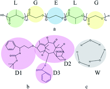
The DPD simulations are performed in a 20 × 20 × 20 cubic box using Materials Studio with Periodic boundary conditions. It should be noted that the previous simulations have proved that this box is sufficient to avoid the finite-size effects.56 The simulations are accomplished in the NVT ensemble. The simulation temperature kBT = 1, the bead density ρ = 3, the friction coefficient γ = 4.5, the cutoff radius rc = 1, these conditions ensured the simulations could relax reasonably and efficiently. In initial configurations, all components are randomly placed in the simulation box. The simulation initially runs for 2 × 10⁵ steps with a time step Δt = 0.05 to achieve thermodynamic equilibrium.In this work, the components comprised of PLGA-b-PEG-b-PLGA copolymer, Dtx drug, and water. Docetaxel (Dtx) is widely used in cancer treatment selected as the model drug. In the PLGA-b-PEG-b-PLGA triblock copolymer, PLGA is the hydrophobic block, PEG is the hydrophilic block. Simple coarse-grained models of components are used in this study. In order to ensure that there is no problem with the model, we referred to the studies of Cao et al.57 and Zhou et al.58 to divide the molecular structure, which is shown in Fig. 1. Several atoms or a functional group are represented as a DPD bead that is highlighted by color. The PLGA-b-PEG-b-PLGA59 is separated into L (green), G (yellow), and E (blue) beads; the Dtx drug is divided into D1 (pink), D2 (pink), D3 (pink) beads; three molecules of water are represented as a bead W (grey). The number of L and G beads in the PLGA block is equal. We set the interaction parameters of different types of beads according to the ref. 57 and 58, which are shown in Table 1.
| L | G | E | D1 | D2 | D3 | W | |
|---|---|---|---|---|---|---|---|
| L | 78.00 | ||||||
| G | 78.04 | 78.00 | |||||
| E | 82.96 | 81.76 | 78.00 | ||||
| D1 | 79.65 | 78.98 | 81.95 | 78.00 | |||
| D2 | 78.15 | 78.01 | 88.43 | 79.50 | 78.00 | ||
| D3 | 78.83 | 78.45 | 80.55 | 78.02 | 78.87 | 78.00 | |
| W | 161.3 | 149.3 | 114.0 | 222.3 | 288.3 | 161.6 | 78.00 |
3. Results and discussion
3.1 The morphologies and structures of blank PLGA-b-PEG-b-PLGA micelles
In order to investigate the aggregation and distribution behavior of the Dtx drugs in the PLGA-b-PEG-b-PLGA micelles, the DPD simulations on the blank PLGA-b-PEG-b-PLGA micelles were initially carried out. The PLGA3-b-PEG7-b-PLGA3 is chosen according to a real PLGA1200-b-PEG1450-b-PLGA1200 copolymer,59 by the relationship60
 | (12) |
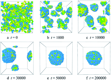 | ||
| Fig. 2 Representative morphology snapshots of the blank PLGA3-b-PEG7-b-PLGA3 micelles at different simulation times. Green, yellow and blue spheres represent beads L, G, and E respectively. | ||
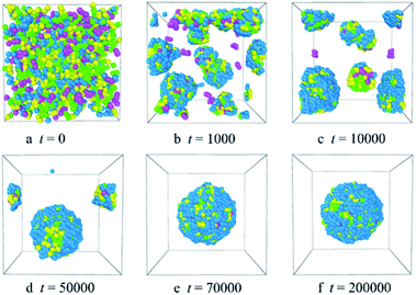
Fig. 2 shows the micellization process of PLGA3-b-PEG7-b-PLGA3 in an aqueous solution is similar to that of most other polymeric micelles.4,31 Specifically, at the beginning of the simulation, i.e. t = 0 steps, all copolymers are randomly mixed, the PLGA3-b-PEG7-b-PLGA3 copolymers exhibit a disordered state [Fig. 2a]. With the evolution of simulation, at t = 1000 steps, we see some PLGA3-b-PEG7-b-PLGA3 copolymers have aggregated and formed clusters for the intermolecular interactions, as shown by [Fig. 2b]. With further increasing the simulation time to t = 10![[thin space (1/6-em)]](https://www.rsc.org/images/entities/char_2009.gif) 000 steps, the smaller PLGA3-b-PEG7-b-PLGA3 clusters merge and form big aggregates [Fig. 2c]. As the simulation progresses, due to the attractive interaction of the aggregates, the aggregates will further grow and form larger aggregates [Fig. 2d t = 30
000 steps, the smaller PLGA3-b-PEG7-b-PLGA3 clusters merge and form big aggregates [Fig. 2c]. As the simulation progresses, due to the attractive interaction of the aggregates, the aggregates will further grow and form larger aggregates [Fig. 2d t = 30![[thin space (1/6-em)]](https://www.rsc.org/images/entities/char_2009.gif) 000 steps]. In the final state t ≥ 50
000 steps]. In the final state t ≥ 50![[thin space (1/6-em)]](https://www.rsc.org/images/entities/char_2009.gif) 000 steps [Fig. 2e and f], all PLGA3-b-PEG7-b-PLGA3 copolymer chains are closely combined and form a stable and complete spherical polymeric micelle, which is consistent with a spherical single-core micelle reported in early research.9 These results indicate that the formative process of the blank PLGA-b-PEG-b-PLGA micelles is an evolution from disordered to the ordered state of distributions of PLGA-b-PEG-b-PLGA copolymers. The hydrophobic PLGA blocks and hydrophilic PEG blocks in an aqueous solution could separate spontaneously. The core of the PLGA-b-PEG-b-PLGA micelle provides the loading space for hydrophobic drugs (e.g. Dtx, DOX), the hydrophilic PEG shell of the micelles exhibits a stabilizing and dispersing effect. Since we have demonstrated that the PLGA-b-PEG-b-PLGA copolymers in an aqueous solution indeed form a micelle, we next focus on exploring the effects of the PLGA-b-PEG-b-PLGA copolymer concentration and composition on the morphologies and structures of the micelle.
000 steps [Fig. 2e and f], all PLGA3-b-PEG7-b-PLGA3 copolymer chains are closely combined and form a stable and complete spherical polymeric micelle, which is consistent with a spherical single-core micelle reported in early research.9 These results indicate that the formative process of the blank PLGA-b-PEG-b-PLGA micelles is an evolution from disordered to the ordered state of distributions of PLGA-b-PEG-b-PLGA copolymers. The hydrophobic PLGA blocks and hydrophilic PEG blocks in an aqueous solution could separate spontaneously. The core of the PLGA-b-PEG-b-PLGA micelle provides the loading space for hydrophobic drugs (e.g. Dtx, DOX), the hydrophilic PEG shell of the micelles exhibits a stabilizing and dispersing effect. Since we have demonstrated that the PLGA-b-PEG-b-PLGA copolymers in an aqueous solution indeed form a micelle, we next focus on exploring the effects of the PLGA-b-PEG-b-PLGA copolymer concentration and composition on the morphologies and structures of the micelle.
To examine whether the system achieves an equilibrium state or not, the time evolutions of the radial distribution functions for the beads of the PLGA-b-PEG-b-PLGA copolymers were investigated. The results are displayed in Fig. S1.† In the initial state t = 0, PLGA-b-PEG-b-PLGA copolymers and water are randomly mixed, the curve shows a low peak at r < 1, which indicates that the interactions between the PLGA3-b-PEG7-b-PLGA3 beads are weak [the black solid line of gcc(r) in Fig. S1†]. With the time evolution t increase from 1000 to 30![[thin space (1/6-em)]](https://www.rsc.org/images/entities/char_2009.gif) 000, due to the significantly aggregate, the width and height of the peak exhibit an increase [the LT magenta dash line, the blue dash-dot line, the orange dash-dot line of gcc(r) in Fig. S1†]. In the final state, the width and height of the peak of gcc(r) in Fig. S1† almost no change, which indicates that the systems have reached equilibration.
000, due to the significantly aggregate, the width and height of the peak exhibit an increase [the LT magenta dash line, the blue dash-dot line, the orange dash-dot line of gcc(r) in Fig. S1†]. In the final state, the width and height of the peak of gcc(r) in Fig. S1† almost no change, which indicates that the systems have reached equilibration.
From the analyses made above, it is known that when the PLGA3-b-PEG7-b-PLGA3 copolymer concentration ccp constantly increases, the interactions between the beads change the structure of micelles from normal spherical to onionlike to columnar to lamellar. The structural changes ensure a minimum contacting area between the hydrophobic groups and water, thus keeping the system stable.
3.2 The morphologies and structures of the Dtx-loaded polymeric micelles
![[thin space (1/6-em)]](https://www.rsc.org/images/entities/char_2009.gif) 000 steps [Fig. 5c], the small clusters gather into several clusters with big size, which corresponds to the blue dash-dot line of gcc(r) in Fig. S5,† the curve shows a broader and higher peak. Meanwhile, most of the Dtx drug beads are absorbed inside the PLGA3-b-PEG7-b-PLGA3 micelles, and a very little left of Dtx drug beads are still dispersed in the aqueous solution. With further increase the simulation steps to t = 50
000 steps [Fig. 5c], the small clusters gather into several clusters with big size, which corresponds to the blue dash-dot line of gcc(r) in Fig. S5,† the curve shows a broader and higher peak. Meanwhile, most of the Dtx drug beads are absorbed inside the PLGA3-b-PEG7-b-PLGA3 micelles, and a very little left of Dtx drug beads are still dispersed in the aqueous solution. With further increase the simulation steps to t = 50![[thin space (1/6-em)]](https://www.rsc.org/images/entities/char_2009.gif) 000 [Fig. 5d], the adjacent micelles can further gather and form larger micelles and the free Dtx drug beads were all diffused into the spherical micelle, which results in the increases of the width and height of the peak [the orange dash-dot line of gcc(r) in Fig. S5†]. That is, as the size of the clusters increases to a certain extent, the morphologies of the aggregates would change from formless structure to spherical structure, i.e. the spherical drug-loaded micelles. As the simulation steps increase to t = 70
000 [Fig. 5d], the adjacent micelles can further gather and form larger micelles and the free Dtx drug beads were all diffused into the spherical micelle, which results in the increases of the width and height of the peak [the orange dash-dot line of gcc(r) in Fig. S5†]. That is, as the size of the clusters increases to a certain extent, the morphologies of the aggregates would change from formless structure to spherical structure, i.e. the spherical drug-loaded micelles. As the simulation steps increase to t = 70![[thin space (1/6-em)]](https://www.rsc.org/images/entities/char_2009.gif) 000 [Fig. 5e], all the micelles conglomerate and form a stable and complete spherical micelle. All Dtx drug beads are distributed inner of the micelle with PEG blocks adsorbed on the outer surface of the micelle. This indicates that the Dtx drugs could be well encapsulated inside the PLGA3-b-PEG7-b-PLGA3 micelles. After that, when the simulation steps further increase to t = 200
000 [Fig. 5e], all the micelles conglomerate and form a stable and complete spherical micelle. All Dtx drug beads are distributed inner of the micelle with PEG blocks adsorbed on the outer surface of the micelle. This indicates that the Dtx drugs could be well encapsulated inside the PLGA3-b-PEG7-b-PLGA3 micelles. After that, when the simulation steps further increase to t = 200![[thin space (1/6-em)]](https://www.rsc.org/images/entities/char_2009.gif) 000, the morphology and size of the spherical micelle and the radial distribution profiles almost no change which suggested that the microphase separation of this system had reached a dynamic equilibrium [Fig. 5f and S5†]. In comparison with the formation process of blank PLGA3-b-PEG7-b-PLGA3 micelles, the Dtx-loaded PLGA3-b-PEG7-b-PLGA3 micelles require more steps to reach equilibrium.
000, the morphology and size of the spherical micelle and the radial distribution profiles almost no change which suggested that the microphase separation of this system had reached a dynamic equilibrium [Fig. 5f and S5†]. In comparison with the formation process of blank PLGA3-b-PEG7-b-PLGA3 micelles, the Dtx-loaded PLGA3-b-PEG7-b-PLGA3 micelles require more steps to reach equilibrium.
![[thin space (1/6-em)]](https://www.rsc.org/images/entities/char_2009.gif) :
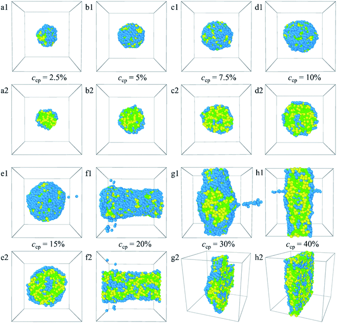
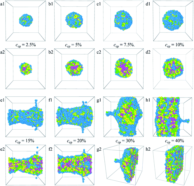
:![[thin space (1/6-em)]](https://www.rsc.org/images/entities/char_2009.gif) 1. The corresponding density distributions with E, L, G, and Dtx drug beads are shown in Fig. S6.† We found that all the Dtx drugs and PLGA3-b-PEG7-b-PLGA3 copolymers aggregate together, whereas the morphologies and structures vary significantly with copolymer concentration. Specifically, as the concentration of the PLGA3-b-PEG7-b-PLGA3 copolymer ccp < 10% [Fig. 6a1–c1 and S6a–c†], the E beads mainly distributed on the outermost layer form the shell of the micelle, all Dtx drug beads are distributed at the center of the micelle and form the hydrophobic core of the micelle [Fig. 6a2–c2], which indicates that a core–shell spherical micelle is formed in the system. This result is supported by the experimental observations of Gao et al.19 Meanwhile, the size of the micelle increases with increasing the PLGA3-b-PEG7-b-PLGA3 copolymer concentration [the red solid dot in Fig. S3†].16 As the concentration of the PLGA3-b-PEG7-b-PLGA3 copolymers increases to ccp = 10% [Fig. S6d†], the density of E beads at the center of the micelle increases, the onionlike structure61 is formed [Fig. 6d1 and d2]. This onionlike structure is comprised of the hydrophilic PEG core, the PLGA hydrophobic middle layer, and the PEG hydrophilic shell [Fig. 6d2]. The Dtx drug beads are distributed at the PLGA middle layer. As the PLGA3-b-PEG7-b-PLGA3 copolymers concentration increases to ccp = 15% and 20% [Fig. S6e and f†], the densities of all the E, L, G, Dtx beads along the x-axis are all significantly greater than 0 and fluctuate around a certain value, the structure of the Dtx-loaded PLGA3-b-PEG7-b-PLGA3 micelle has a significant change from spherical structure to columnar structure25 [Fig. 6e1–f2]. A lamellar structure31 is gradually formed when the concentration of PLGA3-b-PEG7-b-PLGA3 copolymers is further increased to ccp = 30% and 40% [Fig. 6g1–h2 and S6g, h†]. These structures ensure a minimum contacting area of the hydrophobic L, G, D1, D2, D3 beads and water beads W, thus maintaining the stability of the system.
1. The corresponding density distributions with E, L, G, and Dtx drug beads are shown in Fig. S6.† We found that all the Dtx drugs and PLGA3-b-PEG7-b-PLGA3 copolymers aggregate together, whereas the morphologies and structures vary significantly with copolymer concentration. Specifically, as the concentration of the PLGA3-b-PEG7-b-PLGA3 copolymer ccp < 10% [Fig. 6a1–c1 and S6a–c†], the E beads mainly distributed on the outermost layer form the shell of the micelle, all Dtx drug beads are distributed at the center of the micelle and form the hydrophobic core of the micelle [Fig. 6a2–c2], which indicates that a core–shell spherical micelle is formed in the system. This result is supported by the experimental observations of Gao et al.19 Meanwhile, the size of the micelle increases with increasing the PLGA3-b-PEG7-b-PLGA3 copolymer concentration [the red solid dot in Fig. S3†].16 As the concentration of the PLGA3-b-PEG7-b-PLGA3 copolymers increases to ccp = 10% [Fig. S6d†], the density of E beads at the center of the micelle increases, the onionlike structure61 is formed [Fig. 6d1 and d2]. This onionlike structure is comprised of the hydrophilic PEG core, the PLGA hydrophobic middle layer, and the PEG hydrophilic shell [Fig. 6d2]. The Dtx drug beads are distributed at the PLGA middle layer. As the PLGA3-b-PEG7-b-PLGA3 copolymers concentration increases to ccp = 15% and 20% [Fig. S6e and f†], the densities of all the E, L, G, Dtx beads along the x-axis are all significantly greater than 0 and fluctuate around a certain value, the structure of the Dtx-loaded PLGA3-b-PEG7-b-PLGA3 micelle has a significant change from spherical structure to columnar structure25 [Fig. 6e1–f2]. A lamellar structure31 is gradually formed when the concentration of PLGA3-b-PEG7-b-PLGA3 copolymers is further increased to ccp = 30% and 40% [Fig. 6g1–h2 and S6g, h†]. These structures ensure a minimum contacting area of the hydrophobic L, G, D1, D2, D3 beads and water beads W, thus maintaining the stability of the system.
3.3 The Dtx release process under shear flow
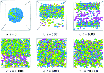
To investigate the release process of the Dtx drugs, we add the shear flow to the system. The concentration of the PLGA3-b-PEG7-b-PLGA3 copolymers is fixed as 10%, the shear rates vary from 0.2 to 5. We found that as the shear rate v < 3.5, the aggregate changes from a spherical micelle to a columnar structure [Fig. S9†]. When the shear rates v ≥ 3.5, the Dtx drug will be released completely from the micelle. Fig. 9 shows the morphologies of the Dtx-loaded micelles at different simulation times under shear flow. In Fig. 9, we found that as the shear rate v = 3.5, the spherical micelle rapidly changes to a columnar structure [Fig. 9a and b]. With the time evolution, the Dtx beads distribution in water increases, which indicates that Dtx drug release from the carrier increases [Fig. 9c and d]. In the final state, at t > 15![[thin space (1/6-em)]](https://www.rsc.org/images/entities/char_2009.gif) 000, the copolymers, Dtx drugs and water are randomly mixed, all Dtx drugs are released [Fig. 9e and f].
000, the copolymers, Dtx drugs and water are randomly mixed, all Dtx drugs are released [Fig. 9e and f].
4. Conclusions
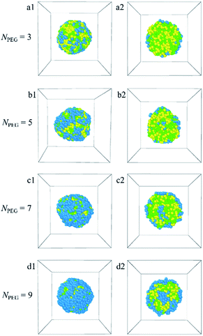
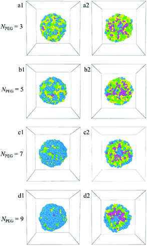
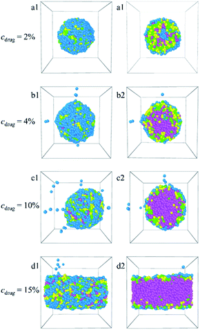
In this paper, the blank and drug-loaded polymeric micelles assembled from PLGA-b-PEG-b-PLGA copolymers and the mixture of PLGA-b-PEG-b-PLGA and docetaxel drugs are investigated by the dissipative particle dynamics (DPD) simulations. The morphologies and structures are dependent on the molecular parameters, such as the PLGA-b-PEG-b-PLGA copolymers concentration, composition, the Dtx drug content and the shear rate. Both the blank PLGA-b-PEG-b-PLGA polymeric micelle and the Dtx-loaded PLGA-b-PEG-b-PLGA micelle undergo the transition from spherical (core–shell) to onionlike (core–middle layer–shell) to columnar and lamellar structure with increasing the copolymer concentration from ccp = 2.5% to 40%. The onionlike structures are comprised of the PEG hydrophilic core, the PLGA hydrophobic middle layer, and the PEG hydrophilic shell. As the structure of Dtx-loaded micelle varies from spherical core–shell structure to core–middle layer–shell onionlike structure, the distribution of the Dtx drugs diffuses from the core to the PLGA middle layer of the aggregate. As the PLGA-b-PEG-b-PLGA copolymer with PEG block length NPEG < 7, the hydrophilic PEG blocks are unable to pack the hydrophobic PLGA completely whether the blank micelles or the Dtx-loaded micelles. Besides, the content of the Dtx drugs also affects the self-assembled structure. When the drug content is under a certain value, spherical structures are gained and their size of them grows up with the increase of the drug content. When the content of the Dtx drugs is to be as high as a certain degree, to ensure the stability of micelles, the structure of Dtx-loaded PLGA3-b-PEG7-b-PLGA3 micelle will change significantly. The Dtx release process is also investigated by adding a shear flow along the x-axis. The morphologies of the Dtx-loaded micelles depend mainly on the shear rates, and with increasing the shear rates from 0.2 to 3.4, the spherical micelles turn into a cylindrical morphology. When the shear rate increases to 3.5, the Dtx drugs released gradually increase until all are released with time evolution.Our investigations indicate that the structures and morphologies of the micelles are strongly correlated to the PLGA-b-PEG-b-PLGA copolymer concentration, composition, the Dtx drugs content, and the shear rate, which provides insights into the fundamental understanding of the Dtx-loaded PLGA-b-PEG-b-PLGA micelles systems. We hope this work could provide important theoretical guidance to design the new drug-loaded micelles.
Author contributions
Conceptualization, D. L.; methodology, D. L., M. W.; validation, D. L.; formal analysis, D. L.; resources, Y. L.; data curation, D. L., Y. L., M. W.; writing—original draft preparation, D. L.; writing—review and editing, D. L.; supervision, D. L., Y. L.; project administration, D. L., Y. L., M. W., J. G.; funding acquisition, Y. L., and D. L.Conflicts of interest
There are no conflicts to declare.Acknowledgements
This work is financially supported by the Basic Scientific Research Project of Hebei Provincial Department of Education (grant JQN2020021), the Medical-Industrial Integration Fund (Grant No. X2021099) of North China University of Science and Technology. We are grateful for the essential support of Hebei Key Laboratory of Data Science and Application and the School of Materials of Sun Yat-sen University.Notes and references
- H. Cabral, K. Miyata, K. Osada and K. Kataoka, Chem. Rev., 2018, 118, 6844 CrossRef CAS PubMed.
- S. Hossen, M. K. Hossain, M. K. Basher, M. N. H. Mia, M. T. Rahman and M. J. Uddin, J. Adv. Res., 2019, 15, 1 CrossRef CAS PubMed.
- J. K. Patra, G. Das, L. F. Fraceto, E. V. R. Campos, M. D. P. Rodriguez-Torres, L. S. Acosta-Torres, L. A. Diaz-Torres, R. Grillo, M. K. Swamy, S. Sharma, S. Habtemariam and H. S. Shin, J. Nanobiotechnol., 2018, 16, 71 CrossRef PubMed.
- Z. X. Yang, H. Q. Zhao, D. L. Wang, L. Yin, K. X. Cai, Z. H. Lin, T. Chen and C. F. Yang, Phys. Chem. Chem. Phys., 2021, 23, 19011 RSC.
- X. B. Wang, L. Wang, S. X. Yang, M. M. Zhang, Q. Q. Xiong, H. Y. Zhao and L. Liu, Macromolecules, 2014, 47, 1999 CrossRef CAS.
- K. Fukushima, R. C. Pratt, F. Nederberg, J. P. K. Tan, Y. Y. Yang, R. M. Waymouth and J. L. Hedrick, Biomacromolecules, 2008, 9, 3051 CrossRef CAS PubMed.
- F. Xu, J. W. Xu, B. X. Zhang and Y. L. Luo, AIChE J., 2015, 61, 35 CrossRef CAS.
- W. Xun, H. Y. Wang, Z. Y. Li, S. X. Cheng, X. Z. Zhang and R. X. Zhuo, Colloids Surf., B, 2011, 85, 86 CrossRef CAS PubMed.
- Z. M. Song, R. L. Feng, M. Sun, C. Y. Guo, Y. Gao, L. B. Li and G. X. Zhai, J. Colloid Interface Sci., 2011, 354, 116 CrossRef CAS PubMed.
- D. E. Owens, Int. J. Pharm., 2006, 307, 93 CrossRef CAS PubMed.
- L. Yu, T. Y. Ci, S. C. Zhou, W. J. Zeng and J. D. Ding, Biomater. Sci., 2013, 1, 411 RSC.
- L. Yu, G. T. Chang, H. Zhang and J. D. Ding, Int. J. Pharm., 2008, 348, 95 CrossRef CAS PubMed.
- G. T. Chang, T. Y. Ci, L. Yu and J. D. Ding, J. Controlled Release, 2011, 156, 21 CrossRef CAS PubMed.
- G. T. Chang, C. Li, W. Y. Lu and J. D. Ding, Macromol. Biosci., 2010, 10, 1248 CrossRef CAS PubMed.
- G. M. Zentner, R. Rathi, C. Shih, J. C. McRea, M. H. Seo, H. Oh, B. G. Rhee, J. Mestecky, Z. Moldoveanu, M. Morgan and S. Weitman, J. Controlled Release, 2001, 72, 203 CrossRef CAS PubMed.
- E. Khodaverdi, F. S. M. Tekie, S. A. Mohajeri, F. Ganji, G. Zohuri and F. Hadizadeh, AAPS PharmSciTech, 2012, 13, 590 CrossRef CAS PubMed.
- A. Vonarbourg, C. Passirani, P. Saulnier and J. P. Benoit, Biomaterials, 2006, 27, 4356 CrossRef CAS PubMed.
- S. Moffatt and R. J. Cristinao, Int. J. Pharm., 2006, 317, 10 CrossRef CAS PubMed.
- Y. Gao, F. Z. Ren, B. Y. Ding, N. Y. Sun, X. Liu, X. Y. Ding and S. Gao, J. Drug Targeting, 2011, 19, 516 CrossRef CAS PubMed.
- S. B. Chen and J. Singh, Int. J. Pharm., 2008, 352, 58 CrossRef CAS PubMed.
- Y. M. Kwon and S. W. Kim, Pharm. Res., 2004, 21, 339 CrossRef CAS PubMed.
- C. Pratoomsoot, H. Tanioka, K. Hori, S. Kawasaki, S. Kinoshita, P. Tighe, J. H. Dua, K. M. Shakesheff and F. R. A. J. Rose, Biomaterials, 2008, 29, 272 CrossRef CAS PubMed.
- L. Yu, Z. Zhang, H. Zhang and J. D. Ding, Biomacromolecules, 2009, 10, 1547 CrossRef CAS PubMed.
- L. Yu, G. T. Chang, H. Zhang and J. D. Ding, J. Polym. Sci., Part A: Polym. Chem., 2007, 45, 1122 CrossRef CAS.
- N. K. Khorshid, K. Z. Zhu, K. D. Knudsen, S. Bekhradnia, S. A. Sande and B. Nyström, Macromol. Biosci., 2016, 16, 1838 CrossRef CAS PubMed.
- D. L. G. Cao, X. X. Zhang, M. Akabar, Y. Luo, H. Wu, X. Ke and T. Y. Ci, Artif. Cells, Nanomed., Biotechnol., 2019, 47, 181 CrossRef CAS PubMed.
- P. J. Hoogerbrugge and J. M. V. A. Koelman, Europhys. Lett., 1992, 19, 155 CrossRef.
- R. D. Groot and K. L. Rabone, Biophys. J., 2001, 81, 725 CrossRef CAS PubMed.
- C. Yang, C. Yuan, W. Liu, J. Guo, D. Feng, X. Yin, W. Lin, P. S. Shuttleworth and H. Yue, Colloids Surf., B, 2019, 178, 56 CrossRef CAS PubMed.
- S. Y. Nie, W. J. Lin, N. Yao, X. D. Guo and L. J. Zhang, ACS Appl. Mater. Interfaces, 2014, 6, 17668 CrossRef CAS PubMed.
- Y. Wang, D. D. Zhu, J. Zhou, Q. L. Wang, C. Y. Zhang, Y. J. Liu, Z. M. Wu and X. D. Guo, Colloids Surf., B, 2015, 136, 536 CrossRef CAS PubMed.
- M. M. Kuru, E. A. Dalgakiran and G. Kacar, Colloids Surf., A, 2021, 629, 127445 CrossRef CAS.
- D. M. Liu, K. Gong, Y. Lin, T. Liu, Y. Liu and X. Z. Duan, Polymers, 2021, 13, 1516 CrossRef CAS PubMed.
- D. M. Liu, K. Gong, Y. Lin, H. F. Bo, T. Liu and X. Z. Duan, Polymers, 2021, 13, 2333 CrossRef CAS PubMed.
- D. M. Liu, M. Y. Yang, D. P. Wang, X. Y. Jing, Y. Lin and X. Duan, Polymers, 2021, 13, 2866 CrossRef CAS PubMed.
- D. M. Liu, Y. Lin, K. Gong, H. F. Bo, D. Y. Li, Z. X. Zhang and W. D. Chen, RSC Adv., 2021, 11, 38316 RSC.
- Y. H. Feng, X. P. Zhang, Z. Q. Zhao and X. D. Guo, Mol. Pharmaceutics, 2020, 17, 1778 CrossRef CAS PubMed.
- B. Y. Li, Y. C. Li and Z. Y. Lu, Polymer, 2019, 171, 1 CrossRef CAS.
- X. Y. Song, H. Guo, J. B. Ta, S. L. Zhao, X. Han and H. L. Liu, Chem. Eng. Sci., 2018, 189, 75 CrossRef CAS.
- T. Seki, N. Arai, D. Suh, T. Ozawa, T. Shimada, K. Yasuoka and A. Hotta, RSC Adv., 2018, 8, 26461 RSC.
- X. D. Ma, Y. R. Zhou, L. S. Zhang, J. P. Lin and X. H. Tian, Nanoscale, 2018, 10, 16873 RSC.
- Y. Jin, D. Y. Guo, B. Li, S. P. Xu, J. Cheng, L. Li, X. F. Wen and P. H. Pi, Phys. Chem. Chem. Phys., 2018, 20, 4074 RSC.
- A. Prhashanna and E. E. Dormidontova, Macromolecules, 2017, 50, 1740 CrossRef CAS.
- A. Prhashanna and S. B. Chen, Polymer, 2017, 118, 22 CrossRef CAS.
- A. J. Peters and T. P. Lodge, Macromolecules, 2017, 50, 6303 CrossRef CAS.
- C. L. Wang, S. Y. Ma, Y. Hu and R. Wang, Langmuir, 2017, 33, 3427 CrossRef CAS PubMed.
- J. J. Li, S. Y. Xiao, Y. X. Xu, S. Zuo, Z. S. Zha, W. D. Ke, C. X. He and Z. S. Ge, ACS Appl. Mater. Interfaces, 2017, 9, 17727 CrossRef CAS PubMed.
- J. M. Borreguero, P. A. Pincus, B. G. Sumpter and M. Goswami, Macromolecules, 2017, 50, 1193 CrossRef CAS.
- K. H. Myint, J. R. Brown, A. R. Shim, B. E. Wyslouzil and L. M. Hall, J. Phys. Chem. B, 2016, 120, 11582 CrossRef PubMed.
- S. Y. Ma, Y. Hu and R. Wang, Macromolecules, 2015, 48, 3112 CrossRef CAS.
- N. K. Li, W. H. Fuss, L. Tang, R. P. Gu, A. Chilkoti, S. Zauscher and Y. G. Yingling, Soft Matter, 2015, 11, 8236 RSC.
- F. R. Cheng, X. W. Guan, H. Cao, T. Su, J. Cao, Y. W. Chen, M. T. Cai, B. He, Z. W. Gu and X. L. Luo, Int. J. Pharm., 2015, 492, 152 CrossRef CAS PubMed.
- R. D. Groot and P. B. Warren, J. Chem. Phys., 1997, 107, 4423 CrossRef CAS.
- R. Xu, M. A. Winnik, F. R. Hallett, G. Riess and M. D. Croucher, Macromolecules, 1991, 24, 87 CrossRef CAS.
- A. Maiti and S. Mcgrother, J. Chem. Phys., 2004, 120, 1594 CrossRef CAS PubMed.
- X. D. Guo, J. P. K. Tan, L. J. Zhang, M. Khan, S. Q. Liu, Y. Y. Yang and Y. Qian, Chem. Phys. Lett., 2009, 473, 336 CrossRef CAS.
- Y. Cao, B. C. Wang, L. C. Yang, Y. Z. Wang and G. K. Singh, J. Appl. Polym. Sci., 2015, 132, 41280 Search PubMed.
- H. Y. Liu, H. Y. Guo and J. Zhou, Acta Chim. Sin., 2012, 70, 2445 CrossRef CAS.
- M. Wang, J. H. Zhan, L. J. Xu, Y. J. Wang, D. Lu, Z. Li, J. H. Li, F. Luo and H. Tan, J. Biomater. Sci., Polym. Ed., 2020, 5, 613 Search PubMed.
- Z. L. Luo and J. W. Jiang, Polymer, 2010, 51, 291 CrossRef CAS.
- P. C. Sun, Y. H. Yin, B. H. Li, T. H. Chen, Q. H. Jin, D. T. Ding and A. C. Shi, J. Chem. Phys., 2005, 122, 204905 CrossRef PubMed.
- M. Chansuna, N. Pimpha and V. Vao-soongnern, J. Polym. Res., 2014, 21, 452 CrossRef.
Footnote |
| † Electronic supplementary information (ESI) available. See https://doi.org/10.1039/d2ra00940d |
| This journal is © The Royal Society of Chemistry 2022 |

