
 Open Access Article
 This Open Access Article is licensed under a Creative Commons Attribution-Non Commercial 3.0 Unported Licence
Solution combustion derived oxygen vacancy-rich Co3O4 catalysts for catalytic formaldehyde oxidation at room temperature
Baolin Muab,
Xianjuan Zhangbc,
Yexin Zhang *bd,
Peng Luc,
Jianying Haoa and
Jian Zhang*bd
*bd,
Peng Luc,
Jianying Haoa and
Jian Zhang*bd
aSchool of Materials Science and Engineering, Taiyuan University of Science and Technology, 66 Waliu Road, Taiyuan 030024, People's Republic of China
bNingbo Institute of Materials Technology & Engineering, Chinese Academy of Sciences, 1219 Zhongguan West Road, Ningbo 315201, People's Republic of China. E-mail: zhangyexin@nimte.ac.cn; jzhang@nimte.ac.cn
cSchool of Materials Science and Chemical Engineering, Ningbo University, 818 Fenghua Road, Ningbo 315211, People's Republic of China
dUniversity of the Chinese Academy of Sciences, 19A Yuquan Road, Beijing 100049, People's Republic of China
First published on 29th March 2022
Abstract
Fabricating abundant oxygen vacancies is crucial for non-noble metal oxides to catalyze formaldehyde (HCHO) oxidation at room temperature. Here, a simple one-pot preparation method via solution combustion was found to produce oxygen vacancy-rich Co3O4 catalysts, avoiding delicate defect engineering. The catalyst was evaluated to result in 52% HCHO conversion in a dynamic flow reaction with ∼6 ppm HCHO, which was higher as compared to some other Co3O4 catalysts prepared in three methods of sol–gel, deposition precipitation and thermal decomposition. The optimal catalyst also exhibited high durability with steady HCHO conversion (∼47%) for more than 50 h. The catalyst characterizations revealed that the explosive solution combustion brought out two particular features of Co3O4, namely, the porous network structure with nano-holes and the abundant oxygen vacancies. The latter was demonstrated to increase the reactive oxygen species and to improve the reducibility and the oxygen transport capacity of Co3O4. The two features and the derived properties are beneficial to the activity and durability of Co3O4. The solution combustion method can serve as a simple and feasible way to fabricate abundant oxygen vacancies to provide room-temperature activity of Co3O4 for HCHO elimination at room temperature.
1. Introduction
Formaldehyde (HCHO) is one of the most common indoor air pollutants, the long-term inhalation of which can induce various respiratory tract diseases such as sinus cancer, lung edema and other diseases.1–3 HCHO was classified as a human carcinogen (Group 1) in June 2004.4 For HCHO elimination, adsorption seems to be an efficient method but requires the periodic replacement or regeneration of the saturated adsorbent.5 In contrast, catalytic oxidation can completely convert HCHO into harmless H2O and CO2 without the depletion of catalyst materials. There are two kinds of catalyst for the reaction, including supported noble metals (such as Pt,6 Pd,7 Au8 and Ag9) and non-noble metals oxides (such as MnO2,10 CeO2 (ref. 11) and Co3O4 (ref. 12)). The former exhibits preeminent activity to catalyze HCHO oxidation at room temperature without any energy consumption. However, the high cost and the susceptibility to toxicity of noble metals impede their widespread practical applications.1 On the contrary, the non-noble metal oxide catalysts with low cost can exhibit high stability but their activity is moderate and high reaction temperatures are generally required at the expense of energy.Among the non-noble metal oxides, Co3O4 exhibits excellent performance for catalytic HCHO oxidation due to the relatively weak Co–O bonds, abundant oxygen vacancy defects, fast oxygen-binding rates, and exceptional redox characteristics.13,14 As such, the oxygen vacancies of Co3O4 can serve as electron-saving ponds to activate O2 molecules to transform into reactive oxygen species such as O−, O2−, and O22−, which involve catalytic HCHO oxidation.15,16 Therefore, the formation of a large number of oxygen vacancies can greatly improve the catalytic activity of Co3O4 for the reaction. To obtain abundant oxygen vacancies, defect engineering has been implemented in metal oxide preparation to induce crystal defects.17 For example, a method involving topochemical transformation13 and another utilizing the strong oxidation of H2O2 (ref. 12) were used to prepare Co3O4 catalysts with abundant oxygen vacancies, which exhibited room-temperature activity for catalytic HCHO oxidation. However, defect engineering in the catalyst preparation is delicate, increasing the difficulty in practice to achieve the high activity to decompose HCHO at room temperature.
Alternatively, the solution combustion preparation method is a convenient way to generate oxygen vacancies in the structure of metal oxides, which is generally based on the reaction between metal nitrates (serving as oxidizers) and fuels (serving as reductants) in aqueous solution.9,18 In the explosive process, the concentrated release of gaseous by-products could expel the oxygen from the reaction media, favouring the generation of oxygen vacancies.18 By this method, Co3O4 was reported to be prepared with oxygen vacancies,19 however, it has not yet been explored for catalytic HCHO oxidation.
Here, we employed the facile one-step solution combustion to prepare an oxygen vacancy-rich Co3O4 catalyst for catalytic HCHO oxidation that was conducted in a dynamic flow reaction mode at room temperature. The as-prepared Co3O4 catalyst demonstrated activity superior to some Co3O4 catalysts prepared by other methods, and also exhibited high durability in a long-time reaction. The catalyst characterizations revealed that the explosive solution combustion resulted in two particular features of the catalyst, namely, a porous network structure with nano-holes, and abundant oxygen vacancies, which account for the catalytic performance of the Co3O4 catalyst.
2. Experimental
2.1 Chemicals
All chemicals used in this work were of analytical grade and were purchased from Sinopharm Chemical Reagent Co., or Aladdin Holding Group.2.2 Preparation of Co3O4
2.3 Catalyst characterization
X-ray diffraction (XRD) patterns were obtained for all as-prepared Co3O4 catalysts using a Bruker D8 Advance DaVinci diffractometer employing Cu Kα radiation (k = 1.5418 Å) and operating at 40 kV and 100 mA. Textural properties of the samples were studied by N2 adsorption–desorption measurements at liquid nitrogen temperature with a physisorption analyser (Micromeritics ASAP2020M instrument). The specific surface area was calculated from the N2 adsorption branch using the Brunauer–Emmett–Teller (BET) mode while the pore-size distribution of the catalysts was calculated from the adsorption branch using the Barrett–Joyner–Halenda (BJH) mode. Raman spectra measurement was performed on Renishaw in-Via-Reflex Raman spectrometer at 514 nm excitation wavelength. The X-ray photoelectron spectroscopy (XPS) analysis was carried out on Kratos Axis Ultra DLD multifunctional X-ray photoelectron spectrometer with an Al Kα radiation source at room temperature and under a vacuum of 10−7 Pa (10−9 torr). The starting angle of the spectrometer was set at 90°, and the spectrum was calibrated to a C 1s peak at 284.6 eV. The scanning electron microscopy (SEM) analysis was performed using a Hitachi S-4800 cold field emission scanning electron microscope. The transmission electron microscopy (TEM) and high-resolution TEM (HRTEM) images were acquired using a JEOL JEM-2100F microscope operated at 200 kV.The temperature-programmed reduction by H2 (H2-TPR) test was conducted on a BELCata-II analyzer (MicrotracBEL). The sample (0.03 g) was placed in a tubular reactor and pre-treated at 300 °C for 1 h under a He flow (50 ml min−1). After cooling to 50 °C, the gas was switched to 10 vol% H2/He, and the temperature was increased from room temperature to 800 °C at a rate of 10 °C min−1 under a gas flow of 50 ml min−1. The consumption of H2 was measured using a thermal conductivity detector (TCD).
The temperature programmed desorption of O2 (O2-TPD) test was conducted using the same instrument. The sample (0.06 g) was placed in the reactor and pre-treated at 300 °C for 2 h under He. After cooling to 50 °C, 10 vol% O2/He with a flow of 50 ml min−1 was introduced for 1 h. The sample was purged by He flow (50 ml min−1) and heated from room temperature to 900 °C at a rate of 10 °C min−1, during which the amount of desorbed O2 was measured using the TCD.
2.4 Evaluation of catalytic activity
The activities of the as-prepared Co3O4 catalysts were evaluated for catalytic HCHO oxidation in a dynamic flow reaction mode. The catalysts at a weight of 0.2 g were packed into a fixed bed quartz tube reactor with an inner diameter of 10 mm. Flowing air carrying 6 ppm HCHO vapour with the relative humidity (RH) of 40–50% was passed through the catalyst bed at a flow rate of 200 ml min−1, which was controlled by a gas mass flowmeter (MF-4003, LANGFAN, China). The weight-hourly space velocity (WHSV) was 60![[thin space (1/6-em)]](https://www.rsc.org/images/entities/char_2009.gif) 000 ml g−1 h−1. The HCHO vapour was generated in a volatile organic compound generator (FD-PG, Friends Experimental Equipment, China), in which a dilute 3.7% HCHO aqueous solution was injected and evaporated and carried out by the air flow. The outlet HCHO concentration was analysed by a phenol spectrophotometric method.13 A gas sample at a volume of 400 ml was absorbed by 20 ml of phenol reagent solution (1 × 10⁻⁴ wt%) for 2 min. Then, 400 μl of ammonium ferric sulphate solution (1 wt%) was added as the colouring reagent. After being shaken and waiting for 15 min in darkness, the HCHO concentration was determined by measuring the light absorbance at 630 nm with a spectrophotometer (UV-752, Shanghai, China).
000 ml g−1 h−1. The HCHO vapour was generated in a volatile organic compound generator (FD-PG, Friends Experimental Equipment, China), in which a dilute 3.7% HCHO aqueous solution was injected and evaporated and carried out by the air flow. The outlet HCHO concentration was analysed by a phenol spectrophotometric method.13 A gas sample at a volume of 400 ml was absorbed by 20 ml of phenol reagent solution (1 × 10⁻⁴ wt%) for 2 min. Then, 400 μl of ammonium ferric sulphate solution (1 wt%) was added as the colouring reagent. After being shaken and waiting for 15 min in darkness, the HCHO concentration was determined by measuring the light absorbance at 630 nm with a spectrophotometer (UV-752, Shanghai, China).
The HCHO conversion rate was calculated using eqn 1
 | (1) |
3. Results
3.1 Activities of catalysts
The activities of the as-prepared Co3O4 catalysts for catalytic oxidation of HCHO (∼6 ppm) at room temperature were evaluated in a dynamic flow reaction mode at a WHSV of 60000 ml g−1 h−1, which were repeated multiple times for each catalyst to guarantee the reliability of the data. The statistical HCHO conversions are shown in Fig. 1a. The mean HCHO conversions over the four catalysts with 0.2 g mass, including Co3O4-SC, Co3O4-SG, Co3O4-DP and Co3O4-TD, were 52, 32, 23 and 24%, respectively. The Co3O4-SC catalyst prepared by the solution combustion method exhibited the best room-temperature activity with the largest HCHO conversion. When the WHSV decreased to 24000 ml g−1 h−1, the HCHO conversion approached 95% (Fig. 1b). The durability of the Co3O4-SC catalyst was tested by the catalytic HCHO oxidation lasting for more than 50 h. As shown in Fig. 1c, the HCHO conversion remained at ∼47% without apparent decline during the durability test, suggesting the high durability of the Co3O4-SC catalyst. For the sake of comprehending the activities, the physical and chemical properties of the four Co3O4 catalysts were studied in the following sections.
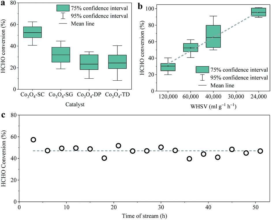 | ||
| Fig. 1 (a) HCHO conversion for the catalytic HCHO oxidation over all Co3O4 catalysts at room temperature (catalyst 0.2 g, WHSV 60000 ml g−1 h−1, HCHO ∼6 ppm, RH 40–50%) with error bars representing 75% and 95% confidence intervals. (b) HCHO conversion over the Co3O4-SC catalyst with different WHSV (HCHO ∼6 ppm, RH 40–50%). (c) HCHO conversion along with time during the durability testing over the Co3O4-SC catalyst at room temperature (catalyst 0.2 g, WHSV 60000 ml g−1 h−1, HCHO ∼6 ppm, RH 40–50%). | ||
3.2 Morphologies and textural properties of catalysts
The morphologies of the four Co3O4 catalysts were observed from the SEM (Fig. 2a1–a4) and TEM (Fig. 2b1–b4) images. The morphology of the Co3O4-SC catalyst (Fig. 2a1 and b1) was a porous network with a lot of voids. In contrast, the other catalysts were composed of aggregated Co3O4 nanoparticles. In the HRTEM image of the Co3O4-SC catalyst (Fig. 2c1), some nano-holes on the Co3O4-SC particles with the size of 2–10 nm were observed as indicated by the dashed rings. The nano-holes were not found on the other catalysts (Fig. 2c2 and c3). | ||
| Fig. 2 SEM (a1–a4), TEM (b1–b4) and HRTEM (c1–c4) images of the catalysts of Co3O4-SC (a1, b1, c1), Co3O4-SG (a2, b2, c2), Co3O4-DP (a3, b3, c3) and Co3O4-TD (a4, b4, c4). The (3 1 1) crystal plane of spinel Co3O4 with the d-spacing of around 0.25 nm (JCPDS 43-1003) is labelled in the HRTEM images (c1–c4). The dashed rings in (c1) indicate the nano-holes on the particles. | ||
The presence of nano-holes on the Co3O4-SC particles was supported by the characterization of textural properties, which were analysed from the N2 adsorption/desorption isotherms in Fig. 3a and the corresponding data are listed in Table 1. According to the IUPAC classification,20 all the catalysts displayed a type IV isotherm with H3 model hysteresis loop. The hysteresis loop came from the interparticle mesopores formed by the particle aggregation as shown by SEM and TEM images (Fig. 2). The hysteresis loop of the Co3O4-SC catalyst was not well-defined in comparison with the other catalysts (Fig. 3a) because its skeleton-like particles were too large to form the interparticle mesopores by aggregation (Fig. 2a1 and b1). This was verified by the calculated pore-size distribution as plotted in Fig. 3b. For the Co3O4-SC catalyst, due to the shortage of interparticle mesopores, the pore distribution in the range of pore size >10 nm was much weaker than those for the other catalysts. However, the Co3O4-SC catalyst displayed some small peaks in the pore size range of <10 nm, which were contributed by the nano-holes on the particles (Fig. 2c1). Although the catalyst had a relatively small total pore volume (0.09 cm3 g−1), its partial pore volume with size <10 nm, which was calculated to be 0.017 cm3 g−1 (Table 1), was largest among those of all the catalysts. The presence of nano-holes on the Co3O4-SC catalyst also resulted in the smallest average pore-size (13.0 nm) among all the catalysts, and contributed to the relatively high BET specific surface area (28.7 m2 g−1) as listed in Table 1.
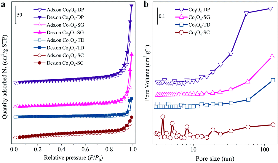 | ||
| Fig. 3 (a) N2 adsorption/desorption isotherms of all the Co3O4 catalysts. (b) Pore-size distribution of the catalysts calculated from the adsorption branch using the BJH method. | ||
| Catalyst | Co3O4-SC | Co3O4-SG | Co3O4-DP | Co3O4-TD |
|---|---|---|---|---|
| a Calculated from the N2 adsorption branch using the BET method.b Estimated at the relative pressure (P/P0) of 0.99 for N2 adsorption.c Determined from the adsorption branch using the BJH method.d Determined by the BET method.e Determined from the XRD patterns using the Bragg's law. | ||||
| BET specific surface area (m2 g−1) a | 28.7 | 20.8 | 30.8 | 7.1 |
| Total pore volume (cm3 g−1) b | 0.09 | 0.23 | 0.34 | 0.08 |
| Partial pore volume with size <10 nm (cm3 g−1) c | 0.017 | 0.006 | 0.006 | 0.001 |
| Average pore size (nm) d | 13.0 | 44.7 | 44.5 | 46.2 |
| Lattice parameter α (Å) e | 8.078 ± 0.002 | 8.068 ± 0.003 | 8.071± 0.003 |
8.072± 0.002 |
3.3 Crystal structures of the catalysts
The XRD patterns in Fig. 4a suggest that the four Co3O4 catalysts had the characteristic structure of spinel Co3O4 (JCPDS 43-1003) without any impurity phase, with the diffraction peaks at 2θ of 19.8°, 31.3°, 38.5°, 44.8°, 59.5° and 65.2°, corresponding to the (1 1 1), (3 1 1), (4 0 0), (5 1 1) and (4 4 0) crystal planes of Co3O4, respectively. The lattice parameters of the Co3O4 catalysts were determined based on Bragg's law with the (3 1 1) peak. As listed in Table 1, the lattice parameter α of the Co3O4-SC catalyst was larger than those of the other catalysts. The lattice expansion of the Co3O4-SC catalyst was an important indicator of abundant oxygen vacancies.21 | ||
| Fig. 4 (a) XRD patterns of all the Co3O4 catalysts and the standard reference of spinel Co3O4 (JCPDS 43-1003 in solid lines). (b) Raman spectra of the catalysts labelled with the vibrational modes of spinel Co3O4. | ||
The existence of oxygen vacancies in the Co3O4-SC catalyst was further corroborated by the Raman spectra as shown in Fig. 4b. For all the catalysts, the vibrational modes of spinel Co3O4, namely, F12g, Eg, F22g, F32g, and A1g, were observed at the Raman shifts of 189, 464, 508, 602, and 678 cm−1, respectively.22 In addition to these bands, interestingly, the Co3O4-SC catalyst exhibited another peak at 683 cm−1 within the range of the A1g mode, which can be ascribed to the partial A1g band shifting to higher frequencies. The blue-shift (∼5 cm−1) of the Raman band can be attributed to the oxygen vacancies due to their photon-confinement effects.13,23,24 Therefore, the XRD and Raman characterizations revealed the most abundant oxygen vacancies of the Co3O4-SC catalyst among all the catalysts.
3.4 Surface compositions of catalysts
The surface compositions of all the Co3O4 catalysts were studied by XPS characterization. Firstly, the surface O/Co atomic ratios were estimated from the XPS full scan spectra and are listed in Table 2 for all the catalysts. Note that the ratios (1.76–3.06) were larger than the stoichiometric O/Co ratio of Co3O4 (1.33), which can be attributed to the surface Co being essentially in the trivalent state associated with excess oxygen species.25 Among all the catalysts, the Co3O4-SC catalyst had the smallest O/Co ratio (1.76), which was approximate to that of a reported carbon/Co3O4 catalyst, being abundant in oxygen vacancies for HCHO oxidation.26 Secondly, the oxidation state of surface Co was determined based on the high-resolution Co 2p spectra in Fig. 5a, which had two spin–orbit components, Co 2p1/2 and Co 2p3/2, located at ∼794.7 and ∼779.6 eV, respectively. By deconvolution, the Co2+ (at ∼796.3 and 781.2 ∼eV) and Co3+ (at ∼794.8 and ∼779.6 eV) ions were distinguished, and the Co3+/Co2+ ratios were calculated as listed in Table 2. Among all the catalysts, the ratio for the Co3O4-SC catalyst was the smallest (1.77), suggesting its lowest Co oxidation state in line with its smallest O/Co ratio. Finally, the surface oxygen species were analysed based on the high-resolution O 1s spectra (Fig. 5b). The deconvolution disclosed three surface oxygen species of the Co3O4 catalysts, including OI (at ∼529.1 eV), OII (at ∼531.0 eV) and OIII (at ∼532.7 eV). OI was the surface lattice oxygen, OII was ascribed to the reactive oxygen species, and OIII corresponded to the chemisorbed water and/or carbonates.26 The proportions of the oxygen species were calculated as listed in Table 2. The number of reactive oxygen species (OII) for the Co3O4-SC catalyst (41.5%) was larger as compared to the other catalysts.| Catalyst | Co3O4-SC | Co3O4-SG | Co3O4-DP | Co3O4-TD |
|---|---|---|---|---|
| a OI is the surface lattice oxygen.b OII is the reactive oxygen species.c OIII is the oxygen of chemisorbed water and/or carbonates. | ||||
| O/Co (at/at) | 1.76 | 2.26 | 3.06 | 2.07 |
| Co3+/Co2+ | 1.77 | 2.13 | 2.14 | 2.85 |
| OI/O (%) a | 48.1 | 40.7 | 30.4 | 48.2 |
| OII/O (%) b | 41.5 | 35.0 | 29.6 | 32.7 |
| OIII/O (%) c | 10.4 | 24.2 | 40.0 | 13.9 |
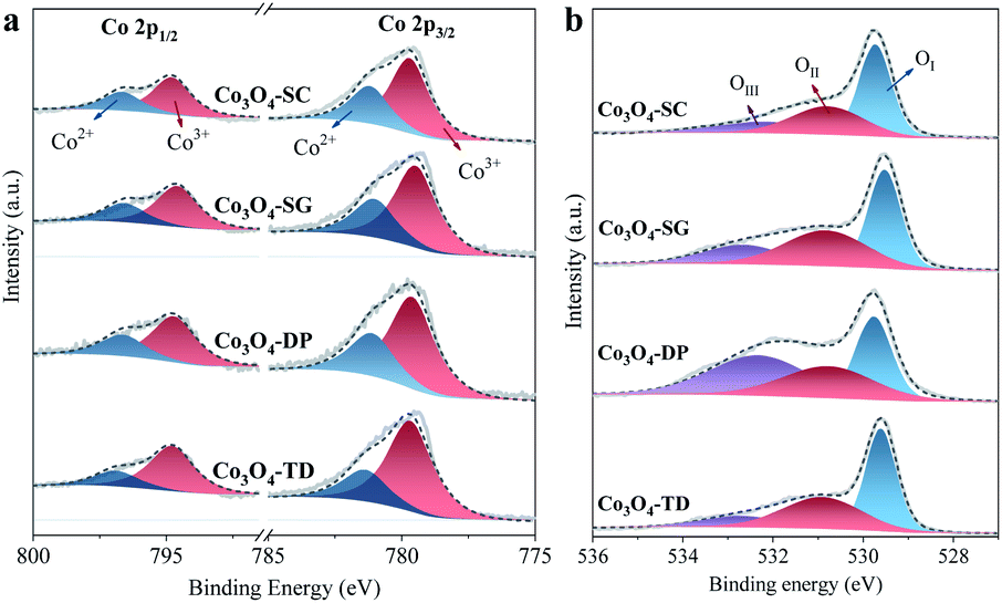 | ||
| Fig. 5 High-resolution XPS spectra of Co 2p (a) and O 1s (b) for all the Co3O4 catalysts. | ||
The XPS characterization suggests that among all the catalysts, the Co3O4-SC catalyst, which is abundant in oxygen vacancies, possesses the smallest O/Co ratio and the lowest Co oxidation state and the richest reactive oxygen species.
3.5 Redox properties of catalysts
The reducibility of the Co3O4 catalysts, which is important for comprehending the catalytic activity, was evaluated by H2-TPR tests. The H2-TPR profiles for all Co3O4 catalysts can be divided into two parts, one for the reduction at <200 °C in Fig. 6a and the other for the reduction >200 °C in Fig. 6b. The reduction at <200 °C was related to the reactive oxygen species,12 which were present for all Co3O4 catalysts. For comparison, the reduction peak areas were calculated by integration with the Shirley baseline subtraction, as labelled in Fig. 6a. The peak areas for the catalysts were in the order of Co3O4-SC > Co3O4-SG > Co3O4-TD > Co3O4-DP, rightly coinciding with the order of the proportion of reactive oxygen species (OII in Table 2). The largest peak area for the Co3O4-SC catalyst further evidenced its richest reactive oxygen species. | ||
| Fig. 6 (a) H2-TPR profiles of all the Co3O4 catalysts in the temperature range <200 °C. The positions and areas of the reduction peaks were labelled, which were calculated by integration with Shirley baseline subtraction. (b) H2-TPR profiles of all the Co3O4 catalysts in the temperature range >200 °C, the positions of the reduction peaks were labelled, which were calculated by deconvolution. (c) O2-TPD profiles of all the Co3O4 catalysts with the labelled positions of the desorption peaks. | ||
The H2-TPR profiles at >200 °C for all Co3O4 catalysts were fitted into three peaks as displayed in Fig. 6b. The first peak at ∼300 °C can be assigned to the reduction of surface hydroxyl groups.27,28 The Co3O4-DP catalyst exhibited the largest proportion of the first peak, which is in agreement with the XPS result that the catalyst possessed the largest proportion of the oxygen of chemisorbed water and/or carbonates (OIII in Table 2). The second peak at ∼360 °C can be ascribed to the reduction of Co3+ to Co2+, whereas the third peak at ∼400 °C was ascribed to the reduction of Co2+ to Co0.12,29 Among all the catalysts, the Co3O4-SC catalyst exhibited the lowest peak temperatures for Co3+/Co2+ and Co2+/Co0 reductions as labelled in Fig. 6b, suggesting its strongest reducibility.
The oxygen transport capacity, another important factor for catalytic oxidation, was characterized by O2-TPD for all the catalysts in Fig. 6c. For each catalyst, a large amount of O2 was desorbed at >750 °C, forming a desorption peak, which can be attributed to the thermal release of lattice oxygen.30 The greatest oxygen transport capacity of the Co3O4-SC catalyst was evidenced by its lowest peak desorption temperature (862 °C) as labelled in Fig. 6c.
Accordingly, the Co3O4-SC catalyst abundant in oxygen vacancies has the strongest reducibility and the greatest oxygen transport capacity among all the catalysts.
4. Discussion
As suggested by the catalyst characterizations, the solution combustion preparation brought out two particular features of Co3O4, namely, the porous network structure with nano-holes and the abundant oxygen vacancies. The appearance of the features can be attributed to the fast, explosive, and exothermic nature of the preparation process, which involves the propagation of a self-sustained exothermic reaction as described in eqn (2).| 27Co(NO3)2 + 28C2H5NO2 = 9Co3O4 + 56CO2(g) + 14N2(g) + 70H2O(g) | (2) |
In the explosive process, a large amount of gaseous by-products (CO2, N2 and H2O) are liberated in an extremely short period of time,18 forming the porous network of Co3O4 with a lot of voids (Fig. 2a1 and b1). The liberated gases also erode the surface of Co3O4 particles, leaving the nano-holes as observed by HRTEM (Fig. 2c1) and as supported by the pore-size distribution (Fig. 3b). The porous network with nano-holes is a kind of hierarchical porous structure, which favours the diffusion of reaction molecules to the catalyst surface for catalysis.31
The abundant oxygen vacancies of Co3O4 are another consequence of gases released in the solution combustion process, which could expel the oxygen from the reaction media.18 This can be evidenced by the smaller O/Co ratio and the lower Co oxidation state of Co3O4 as compared to those in the other methods (XPS analysis in Table 2). The abundant oxygen vacancies were proved by XRD and Raman characterizations (Fig. 3 and Table 1).
As mentioned in the Introduction section, the abundant oxygen vacancies facilitated the transformation of O2 into reactive oxygen species, which was verified by the XPS analysis in Table 2 and H2-TPR analysis in Fig. 6a. Moreover, the abundant oxygen vacancies improved the reducibility and the oxygen transport capacity of Co3O4 as suggested by the H2-TPR in Fig. 6b and the O2-TPD in Fig. 6c, respectively. The reactive oxygen species were enough active to oxidize HCHO, accounting for the highest room-temperature activity of the Co3O4 catalysts (Fig. 1a). The improved reducibility and oxygen transport capacity are beneficial for maintaining the reduction–oxidation cycles for catalytic HCHO oxidation, being responsible for the high durability of the Co3O4 catalyst in the reaction for more than 50 h (Fig. 1c).
5. Conclusions
The Co3O4 catalyst prepared using the solution combustion method was evaluated for the HCHO oxidation elimination at room temperature in comparison with the Co3O4 catalysts prepared by other methods. In the dynamic flow reaction with ∼6 ppm HCHO, the catalyst showed the highest HCHO conversion (∼52%) and also exhibited high durability with steady HCHO conversion (∼47%) for >50 h. Through catalyst characterizations, two particular features of the optimal catalyst were revealed, namely, the porous network structure with nano-holes and the abundant oxygen vacancies, originating from the concentrated release of a large amount of gaseous by-products in the explosive solution combustion process. The two features can be used to account for the catalytic performance. The porous network structure with nano-holes favours the diffusion of the reaction molecules to the catalyst surface, while the abundant oxygen vacancies facilitate the formation of reactive oxygen species and improve the reducibility and the oxygen transport capacity, which are beneficial for the reduction-oxidation cycles of Co3O4 catalyst for catalytic HCHO oxidation. The one-step solution combustion provides a facile and feasible way to develop oxygen vacancy-rich Co3O4 catalysts for catalytic HCHO oxidation at room temperature.Author contributions
Baolin Mu: investigation, writing – original draft, data curation, formal analysis, visualization; Xianjuan Zhang: investigation, data curation, formal analysis; Yexin Zhang: conceptualization, methodology, validation, visualization, writing – review & editing; Peng Lu: resources, writing – review & editing; Jianying Hao: resources; Jian Zhang: resources, project administration, funding acquisition, supervision, writing – review & editing.Conflicts of interest
There are no conflicts to declare.Acknowledgements
The work was supported by Key Research Program of Frontier Sciences, Chinese Academy of Sciences (QYZDB-SSW-JSC037), and Fujian Institute of Innovation, Chinese Academy of Sciences (FJCXY18020202).References
- W.-C. Chung, D.-H. Mei, X. Tu and M.-B. Chang, Catal. Rev., 2018, 61, 270–331 CrossRef.
- L. Miao, J. L. Wang and P. Y. Zhang, Appl. Surf. Sci., 2019, 466, 441–453 CrossRef CAS.
- J. Chen, D. Yan, Z. Xu, X. Chen, X. Chen, W. Xu, H. Jia and J. Chen, Environ. Sci. Technol., 2018, 52, 4728–4737 CrossRef CAS PubMed.
- L. Zhang, C. Steinmaus, D. A. Eastmond, X. K. Xin and M. T. Smith, Mutat. Res., Rev. Mutat. Res., 2009, 681, 150–168 CrossRef CAS PubMed.
- S. Suresh and T. J. Bandosz, Carbon, 2018, 137, 207–221 CrossRef CAS.
- Z. X. Yan, Z. H. Xu, B. Cheng and C. J. Jiang, Appl. Surf. Sci., 2017, 404, 426–434 CrossRef CAS.
- L. N. Zhang, B. J. Zhang, P. Xue, J. W. Li, Z. Zhang, Y. L. Yang, S. Wang, J. D. Lin, H. G. Liao, Y. Wang, Y. L. Yao, S. L. Wan and H. F. Xiong, ChemCatChem, 2021, 13, 4133–4141 CrossRef CAS.
- J. Y. Huang, H. Liang, J. X. Ye, D. T. Jiang, Y. L. Sun, X. J. Li, Y. F. Geng, J. Q. Wang, Z. F. Qian and Y. Du, Sens. Actuators, B, 2021, 346, 9 Search PubMed.
- J. Wang, Y. Zhang, L. Kuang, J. Yang, C. Xu, B. Mu, J. Li, P. Lu, W. Song, W. Wang, A. Wu, X. Liang and J. Zhang, Chem. Eng. J., 2021, 424, 130320 CrossRef CAS.
- F. Liu, S. Rong, P. Zhang and L. Gao, Appl. Catal., B, 2018, 235, 158–167 CrossRef CAS.
- J. Liu, Y. Zheng, Q. Zhu, Y. Dong, S. Lu, B. Peng, Y. Chen, S. Zeng and K. Li, Catal. Surv. Asia, 2020, 24, 207–218 CrossRef CAS.
- J. Chen, M. Huang, W. Chen, H. Tang, Y. Jiao, J. Zhang, G. Wang and R. Wang, Ind. Eng. Chem. Res., 2020, 59, 18781–18789 CrossRef CAS.
- Z. Wang, W. Wang, L. Zhang and D. Jiang, Catal. Sci. Technol., 2016, 6, 3845–3853 RSC.
- M. S. Kamal, S. A. Razzak and M. M. Hossain, Atmos. Environ., 2016, 140, 117–134 CrossRef CAS.
- J. Deng, W. Song, L. Chen, L. Wang, M. Jing, Y. Ren, Z. Zhao and J. Liu, Chem. Eng. J., 2019, 355, 540–550 CrossRef CAS.
- C. Ma, C. Yang, B. Wang, C. Chen, F. Wang, X. Yao and M. Song, Appl. Catal., B, 2019, 254, 76–85 CrossRef CAS.
- G. Zhuang, Y. Chen, Z. Zhuang, Y. Yu and J. Yu, Sci. China Mater., 2020, 63, 2089–2118 CrossRef CAS.
- F. Kermani, S. Mollazadeh and J. Vahdati Khaki, Ceram. Int., 2019, 45, 13496–13501 CrossRef CAS.
- G. P. Kumar, I. N. Jawahar and V. Biju, J. Mater. Sci.: Mater. Electron., 2021, 32, 14919–14931 CrossRef CAS.
- K. A. Cychosz and M. Thommes, Engineering, 2018, 4, 559–566 CrossRef CAS.
- M. Tyunina, O. Pacherova, T. Kocourek and A. Dejneka, Sci. Rep., 2021, 11, 15247 CrossRef CAS PubMed.
- V. G. Hadjiev, M. N. Iliev and I. V. Vergilov, J. Phys. C: Solid State Phys., 1988, 21, L199–L201 CrossRef.
- L. Li, J. Yan, T. Wang, Z.-J. Zhao, J. Zhang, J. Gong and N. Guan, Nat. Commun., 2015, 6, 5881 CrossRef PubMed.
- A. Naldoni, M. Allieta, S. Santangelo, M. Marelli, F. Fabbri, S. Cappelli, C. L. Bianchi, R. Psaro and V. Dal Santo, J. Am. Chem. Soc., 2012, 134, 7600–7603 CrossRef CAS PubMed.
- N. Bahlawane, E. Fischer Rivera, K. Kohse-Höinghaus, A. Brechling and U. Kleineberg, Appl. Catal., B, 2004, 53, 245–255 CrossRef CAS.
- R. Li, Y. Huang, D. Zhu, W. Ho, J. Cao and S. Lee, Environ. Sci. Technol., 2021, 55, 4054–4063 CrossRef CAS PubMed.
- Z. Yan, Z. Xu, J. Yu and M. Jaroniec, Appl. Catal., B, 2016, 199, 458–465 CrossRef CAS.
- Q. Wang, C. Zhang, L. Shi, G. Zeng, H. Zhang, S. Li, Y. Zhang, P. Wu, Y. Fan and G. Liu, iScience, 2018, 9, 487–501 CrossRef CAS PubMed.
- S. Mo, S. Li, J. Li, Y. Deng, S. Peng, J. Chen and Y. Chen, Nanoscale, 2016, 8, 15763–15773 RSC.
- S. Zhang, X. Zhu, C. Zheng, D. Hu, J. Zhang and X. Gao, Aerosol Air Qual. Res., 2017, 17, 2317–2327 CrossRef CAS.
- Q. Sun, Z. Dai, X. Meng and F.-S. Xiao, Chem. Soc. Rev., 2015, 44, 6018–6034 RSC.
| This journal is © The Royal Society of Chemistry 2022 |