
 Open Access Article
 This Open Access Article is licensed under a Creative Commons Attribution-Non Commercial 3.0 Unported Licence
Optimizing graphene oxide membranes for effective removal of dyes by modulating the reduction degree and doped nitrogen†
Jin Baiab,
Jianren Huang bc,
Qirui Wubc and
Lunhui Guan*b
bc,
Qirui Wubc and
Lunhui Guan*b
aCollege of Chemistry, Fuzhou University, Xueyuan Road No. 2, Fuzhou 350108, China
bCAS Key Laboratory of Design and Assembly of Functional Nanostructures, Fujian Key Laboratory of Nanomaterials, Fujian Institute of Research on the Structure of Matter, Chinese Academy of Sciences, Fuzhou, Fujian 350002, China. E-mail: guanlh@fjirsm.ac.cn
cCollege of Mechanical Engineering and Automation, Fuzhou University, Xueyuan Road No. 2, Fuzhou 350108, China
First published on 26th April 2022
Abstract
The excellent mechanical and chemical characteristics of graphene oxide (GO) enable their potential application in the realm of membrane separation. However, the expansion and instability of GO nanosheets in water limit its application. In this work, nitrogen-doped GO (NGO) was obtained by a harmless hydrothermal reduction method. The obtained NGO films were attached to a polyvinylidene fluoride support membrane by vacuum filtration. By changing the hydrothermal reaction temperature, the reduction degree of GO and doping amount of nitrogen was adjusted to control the inter-layer structure and permeability of NGO. The defect of NGO nanosheets and the reduction of oxygen-containing functional groups could accelerate the transportation of water molecules through the inter-layer space of the hydrophobic graphene sheets. Significantly, the polarization and high adsorption energy of pyridine-N serve as a supplement to the exclusion mechanism of the inter-layer spacing. NGO membranes have better permeability than the initial GO membranes without sacrificing the rejection rate. The optimized NGO film has a significant rejection rate of above 99% for various dyes, such as methylene blue, Congo red and methyl blue.
1. Introduction
Water resources are the most critical foundation of human society and the carrier of ecological balance. With the rapid development of the population, the demand for industrial water continues to expand. It is estimated that by 2025, the annual industrial water consumption will increase by 50% over 1995.1 Compared with traditional water purification methods, membrane separation has many advantages, such as low energy consumption, high selectivity, and negligible side reactions.2,3In recent years, significant progress have been achieved to obtain two-dimensional materials with a pronounced sieving effect of the mechanical distance between layers, which has become a new hot spot in the study of membrane separation. Controlling the inter-layer spacing and nanochannels of a membrane made from graphene oxide (GO), MoS2, metal–organic frameworks, and MXene, are vital for specific molecular or ion sieving.4–9
At the same time, the membranes show extraordinary permeability in gas separation, water purification and seawater desalination.10–12 GO, a typical two-dimensional material, contains a variety of hydrophilic oxygen-containing functional groups.13 The strong hydrophilicity and electronegativity of these functional groups provide advantages for water purification.14 For example, Han et al. proposed a method to prepare ultra-thin graphene (≈22–53 nm thick) NF film using chemical conversion graphene, which has a significant permeability (21.8 L m−2 h−1 bar−1) and a manifest organic dye filtration performance (>99%).15 Wei et al. found that membranes prepared by slow deposition had significant desalination, and the water flux was about three times as much as that of film prepared by prompt deposition.16
However, the hydrogen bonds formed in the oxidation zone of GO with water molecules strongly hinder the transmission speed of water in the sheet. Joshi et al. demonstrated that the ion hydration radius limited the sieving effect of the laminated GO film, and it has a particularly steep cut-off point at ∼4.5 Å.17 To solve these problems, researchers have managed to achieve a balance between GO's excellent modifiability and good filtration and separation performance by adjusting the lamella pores, modifying functional groups and limiting the interval between the lamellas.18 Li et al. used hydrogen peroxide and GO hydrothermal to make holes on the GO surface, keeping the Na2SO4 rejection rate at 90% while increasing the water flux.19 Kang et al. re-oxidized rGO to make pores so that the membrane exhibited ultra-fast water permeability (586 L m−2 h−1 bar−1) and precise molecular sieving (MWCO: 269 Da).20 Mi et al. directly filled GO with functional groups with different molecular weights and electronegativity to control the gap between GO sheets.21 Huang et al. demonstrated the possibility of partially reduced GO membranes for water treatment, constructed reduced GO membranes through a hydrothermal reduction method, and they were illustrated that the retention of partial oxygen-containing groups is the key element for rGO film formation.22 Fand et al. regulated the reduction of GO through controlling the time of hydrothermal reactions, and the prepared rGO film was resistant to Methyl blue, Congo red and Crystals.23 The interception rate of purple is over 99%. Song et al. prepared nitrogen-doped reduced GO by a hydrothermal method, the incorporation of nitrogen can change the atomic content and bonding structure, resulting in a narrower interlayer spacing and a more polarized surface than GO, and it was hypothesized that it could be used in ion screening membranes.24
Compared with the pristine GO membranes, laminated nitrogen-doped GO membranes provide size-dependent permeability of hydrated ions due to the electrostatic characteristics, and the polarized pyridine N. However, the detailed structure–property relationship between the functional group of GO-based membrane for removing dye has not been studied yet. Here, as demonstrated in Fig. 1, we propose a harmless and convenient method to dope GO with nitrogen through a hydrothermal method, which can be easily adjusted by adjusting the temperature of the hydrothermal reaction. The obtained nitrogen-doped graphene oxide (NGO) film was attached to a polyvinylidene fluoride (PVDF) substrate with a vacuum filtration method. Under the modified conditions, the optimized NGO membranes presented high water flux and rejection to Methylene blue (MnB), Rhodamine B (RB), Congo red (CR) and Methyl blue (MB). The physical characterization revealed that the pyridine N played a key role, which could improve the screening performance of the membrane-based its size repulsion and electrostatic interaction.
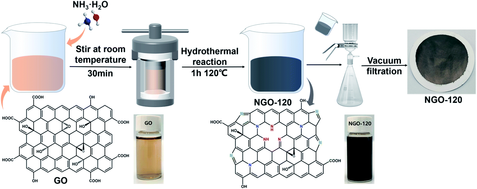 | ||
| Fig. 1 Schematic diagram of NGO preparation. | ||
2. Experimental methods
2.1. Materials
GO powder (0.5–5 μm, 99%) was gained from XFNANO Materials Tech. Co., Ltd (Nanjing, China). MnB (Mw = 319.85, AR, ≥99.0%), RB (Mw = 479.01, AR, ≥99.0%), CR (Mw = 696.98, AR, ≥99.0%) and MB (Mw = 799.80, AR, ≥99.0%) dyes were purchased from China National Pharmaceutical Co., Ltd (Beijing, China). Poly(vinylidene fluoride) (PVDF) membranes (diameter = 5 cm, pore size = 0.22 μm) were gained from Shanghai Xing Ya Co., Ltd (China).2.2. Preparation of NGO membranes
First, GO powder was dispersed in ultrapure water by sonicating to acquire a GO dispersion of 0.1 mg mL−1. Then, 40 mL of the prepared GO dispersion was mixed with 10 mL of concentrated ammonia water, and stirred at room temperature for 30 minutes. Then it was poured into a 100 mL Teflon-lined stainless-steel autoclave, and hydrothermally reacted for 1 hour. The reaction temperatures were kept at 100 °C, 120 °C, and 140 °C, respectively. A series of NGO dispersions were prepared, and the samples were named NGO-x, where x represents the reaction temperature. Finally, the prepared 50 mL of NGO-x dispersion was diluted with ultra-pure water to 100 mL, dispersed and sonicated for 30 minutes, and the NGO film was attached to the PVDF membrane by vacuum filtration (effective area was 12.56 cm2).2.3. Membrane performance analysis
An ultrafiltration cup filter (Amicon® Stirred Cell 50 mL, Merck KGaA Co., Ltd, Germany) was used to test the performance of the NGO-x membrane. The experimental pressure is 0.1 MPa. The valid penetration area is 9.6 cm2, and the concentration of the original dye solution is 200 ppm. The filtration performance of the membrane is reflected by the water flux J (L m−2 h−1 bar−1) and the rejection rate R (%), which apply the following formula to evaluate
Among them, V (L) represents the volume of filtration solution on the permeate side. A (m−2) represents the effective filter area, t (h) represents the filtration time, and P (bar) represents the working pressure.
3. Results and discussion
The schematic diagram of NGO-x prepared with NGO-120 as an example in Fig. 1 indicated that the GO dispersion was brownish yellow, while the NGO-120 dispersion after hydrothermal treatment changed to black. A similar color also appeared on the GO and NGO-120 membranes formed by the corresponding suction filtration, implying that the graphene oxide was reduced during the hydrothermal process. This may be related to the recovery of graphite sp2 bonds caused by the reduction of graphite oxide.25 In addition, these membranes can be stretched and bent freely (Fig. S1b†), showing good mechanical properties and flexibility.3.1. Physical properties of the NGO membranes
The surface and cross-sectional morphology of the NGO-x film were observed by SEM. As shown in Fig. 2(a)–(d), the surface morphology of thin film NGO-x showed a uniform and densely packed randomly oriented graphene shape without any agglomeration, which given rise to its isotropic characteristics. This can be attributed to directional flow caused by filtration during manufacturing. Under vacuum filtration pressure, due to the large aspect ratio of graphene sheet, 2D NGO-x tended to self-adjust the base plane parallel to the membrane plane, resulting in significant alignment of GO sheet. The degree of surface wrinkles of NGO-x membranes increased first and then decreased, compared with the pristine GO membranes, implying that during the restoration process, both the defect and the restored sp2 domain increased, but the growth rate of the defect was faster than the restored sp2 domain, resulting in more obvious wrinkles of the NGO-100 membrane than that of the GO membrane. As shown in Fig. 2c and d, when the hydrothermal treatment temperature continued to rise, more and more sp2 regions were recovered, and the surface of the reduced graphene film became smoother, making the NGO-120 and NGO140 films gradually smooth. In the cross section of the membrane shown in Fig. 2e–h, we can see that GO and NGO-x were successfully deposited during the manufacturing process to form a dense film with a “sandwich” -like structure, which can be attributed to the directional flow caused by filtration. The membrane presented a layered structure that provides a nanochannel for the transport of water molecules. From NGO-100 to NGO-140, the layer structure was stacked densely.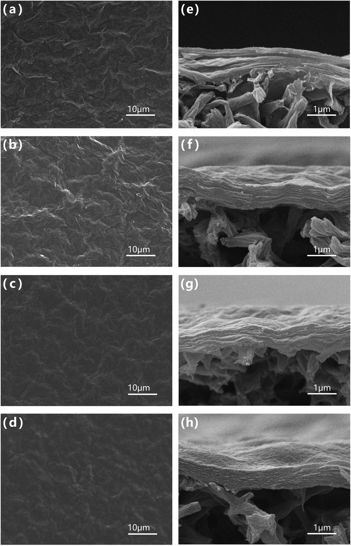 | ||
| Fig. 2 SEM images of (a–d) surfaces and (e–g) cross sections of NGO-x membranes: (a, e) GO, (b, f) NGO-100, (c, g) NGO-120, (d, h) NGO-140. | ||
The inter-layer distance of the nanosheets of the GO and NGO-x films at different reaction temperatures could be easily measured by XRD. As shown in Fig. 3a, after the hydrothermal reaction, the distribution and intensity of the peak changed prominently. As the degree of reduction increases, the inter-layer spacing of NGO nanosheets continue to decrease.26 The distinct XRD peak of GO was at 10.3°, indicating the inter-layer spacing is 0.92 nm. After the reaction at 100 °C, a new peak at 20.3° (inter-layer spacing of 0.43 nm) appeared, at the same time, the 10.3° peak of the raw material GO disappeared, indicating that the graphite structure was restored due to reduction after N-doping.27 As the temperature increased, the NGO peak position continued to move back, at 120 °C it was 20.8° (inter-layer spacing 0.42 nm), and at 140 °C it was 21.4° (inter-layer spacing 0.41 nm). It implied that the reaction temperature increased, the reaction rate increased, and the inter-layer spacing decreased.
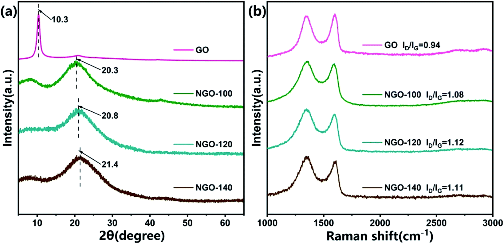 | ||
| Fig. 3 (a) XRD patterns and (b) Raman spectra of NGO membranes. | ||
Raman spectroscopy is an effective technique to commonly resolve the disordered composition of carbon-based materials commonly.28 The D band centered at 1350 cm−1 is derived from the lattice defects of carbon structure. The G band centered at 1585 cm−1 is originated from the in-plane vibration of sp2 carbon framework.29 The disorders and defects (such as wrinkles, pores and edges) of the graphene nanosheets are determined by intensity ratios of the D band to the G band (ID/IG).30 The increase of defects in graphene sheets helps to accelerate the transportation of water molecules.31 As the hydrothermal reaction temperature increased from 0 °C to 120 °C, the ID/IG value increased significantly from GO to NGO-x. These results indicated that the removal of oxygen-containing functional groups and nitrogen doping promoted the formation of many smaller sp2 carbon domains. The degree of disorder and defects in NGO-x had also increased. When the reaction temperature exceeded 120°, the ID/IG value hardly increased, indicating that the disorder degree and defects of NGO-x did not change significantly with the continuous increase of the temperature. Similarly, in the FT-IR spectra analysis (Fig. S2†), the samples can be seen to increase with the reaction temperature, and the oxygen-containing peaks such as –OH (∼3204 cm−1), C![[double bond, length as m-dash]](https://www.rsc.org/images/entities/char_e001.gif) O (∼1720 cm−1) and C–OH (∼1220 cm−1) gradually weakened or even disappeared. At the same time, the appearance of C–N (∼1050 cm−1) and N–H (∼1580 cm−1) peaks proved that GO was partially reduced with the successful incorporation of nitrogen during the hydrothermal process.
O (∼1720 cm−1) and C–OH (∼1220 cm−1) gradually weakened or even disappeared. At the same time, the appearance of C–N (∼1050 cm−1) and N–H (∼1580 cm−1) peaks proved that GO was partially reduced with the successful incorporation of nitrogen during the hydrothermal process.
3.2. Functional groups of the NGO-x membranes on the dye rejection performance
The chemical composition and properties of the functional groups in the samples were confirmed by XPS. As shown in Fig. 4a, the XPS results of NGO-x powder clearly display the existence of C 1s (∼285 eV), N 1s (∼400 eV), and O 1s (∼582 eV). Fig. 4b and S3–S5† shows that compared with the original GO, as the reaction temperature increased, the intensity of the C 1s and N 1s peaks in NGO-x increased, while the O 1s peak decreased. The N element content was within 3.5–6.0%. The N 1s peak of NGO-x was further deconvoluted into three different valence states: ∼398.5 eV (pyridine N), ∼399.9 eV (pyrrole N) and ∼401.2 eV (graphite N). A pyridine nitrogen atom bonded with two carbon atoms at the edge of a carbon plane or at a graphene defect, leaving a local electron pair perpendicular to the graphite π network.32 Pyrrole N is the majority in NGO-x. In the nitrogen bond configuration, the high binding energy of graphite N demonstrates that the nitrogen atom replaces the carbon atom on the base surface. The bonding configuration makes the NGO sheet layer in terms of polarized surface charges, which will affect the electrostatic interaction on the plane.33–35 As the doping reaction temperature increased, the content of pyridine N and pyrrole N increased overall, while the content of graphite N remained roughly unchanged, which indicates that nitrogen doping was mainly through the substitution of oxygen-containing groups.36 At the same time, the Fig. 4c results show that the increased doping reaction temperature can incorporate more pyridine N into the carbon network, indicating that our method was conducive to the constitution of pyridine N. However, when the temperature reached 140 °C, the N content decreased. This may be because NH3 efficiently reacted with the oxygen functional groups (epoxy groups, carboxylic acids and hydroxyl substances) present on the GO surface or the edge of the graphite to form intermediates. The temperature was too high and too fast to be restored in advance.27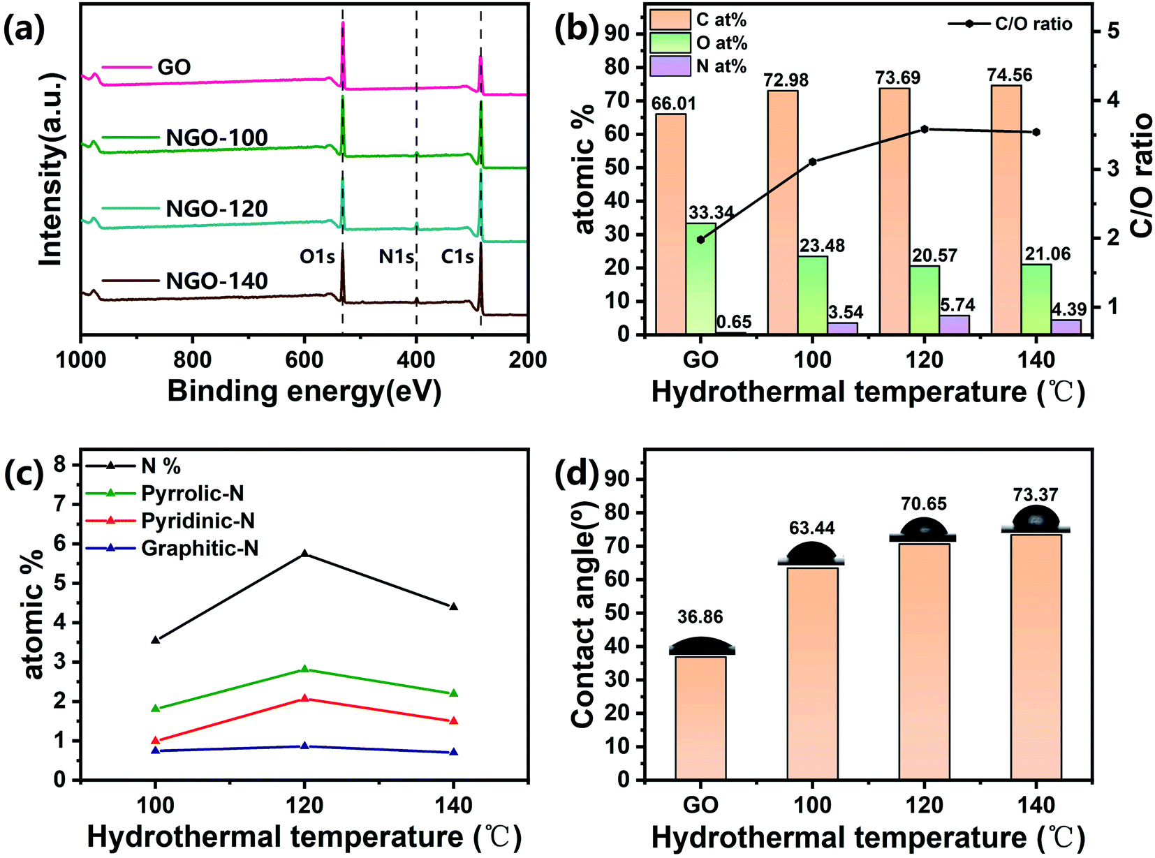 | ||
| Fig. 4 (a) XPS spectra of GO and NGO-x powder samples; (b) chemical composition obtained by XPS analysis of NGO-x powder; (c) the relationship between functional nitrogen-containing groups and hydrothermal temperature; (d) water contact angle of NGO-x membranes. | ||
According to slip flow theory, the increase in water flux can be attributed to promoting non-oxidized sp2 carbon framework, the rise of defects, and the lessen of oxygen-containing groups.37 At the same time, NGO-120 has the highest N content and pyridine-N content. Because in addition to the effect of inter-layer spacing, the polarization and high adsorption energy of pyridine-N can interact with more charged solutes as a supplement to the exclusion mechanism of inter-layer spacing.24 This can also indicate that although the oxygen-containing functional groups are not entirely removed after the nitrogen-doped hydrothermal reaction, the rejection rate and water flux are equivalent to the performance of the NGO membrane previously studied.38
As the XPS analysis shows (Fig. 4b and S6†), when the reaction temperature increases, the C/O ratio of the sample gradually rises. After the graphene oxide was reduced, the hydrophilic hydroxyl groups, for instance, carboxyl and carboxyl groups were removed partly, which is related to the hydrophilicity of NGO-x membranes. The membrane's hydrophilicity is tightly connected to the permeability of the water separation process.23 The hydrophilicity/hydrophobicity of the material was assessed by gauging the water contact angle of the loaded surface of the sample membrane (Fig. 4d). The contact angles of GO and NGO-x membranes are 36.86°, 63.44°, 70.65°, and 73.37°, respectively. However, the contact angle of the sample film was still less than 90°, indicating that GO is partially reduced after the nitrogen doping reaction, and the remaining oxygen-containing functional groups make the NGO-x film retain a certain hydrophilicity and allow water molecules to pass through.
3.3. Dye rejection performance evaluations of the optimized NGO-120 membranes
A series of measurements were conducted to measure the performance of NGO-x membranes, as shown in Fig. 5. By adjusting the volume of the NGO dispersion, the connection between the performance of the NGO film and the deposition amount on the PVDF support film was evaluated (Fig. 5a). With the increase in the deposition of reaction products, the water flux of the NGO-120 membrane decreased, approximately linearly, and the rejection rate of MB dye increased from 83% to 99.6% when the load mass was 0.08 mg cm−2, while the improvement was slow afterwards. When the number of graphene nanosheets on the PVDF support membrane increased, it resulted in the thicker nanosheets on the membrane, and more sheets were applicable to trap MB molecules, but the nanochannels for the transportation of water molecules have become longer, thereby increasing transportation resistance.39,40 As to survey the separation capability of the membrane, GO and NGO-x membranes were tested for the retention of MB dye. As shown in Fig. 5b, the water flux of the original GO membrane was 5 L m−2 h bar−1, but the rejection rate was only 25%. This is because water molecules will form hydrogen bonds with the hydroxyl carboxyl groups in the GO sheet, which will increase the transport resistance of water molecules while expanding the distance between the nanosheets.18 The rejection rate of the NGO-x membrane increased significantly after the nitrogen doping reaction, and remained above 96% overall, but the water flux first increased and then decreased, reaching the maximum value of 9.8 L m−2 h−1 bar−1 at NGO-120. The interception rate also had the highest value of 99.8%. Due to the low hydrothermal temperature of NGO-100, there would be more oxygen-containing functional groups in the lamellae, leading to a large gap between the lamellae and the formation of hydrogen bonds between the functional groups and water to hinder the passage of water molecules, resulting in a rejection rate of about 98% with a water flux of only 5 L m−2 h−1 bar−1. When the reaction temperature increased, NGO-140 caused the lamellae to stack themselves due to the excessively high hydrothermal temperature, which caused the small lamellae spacing. At the same time, the dispersibility of the oxygen-containing functional groups was low, and the rejection rate and water flux were both low, resulting in a rejection rate of 95% with the water flux of only 6 L m−2 h−1 bar−1.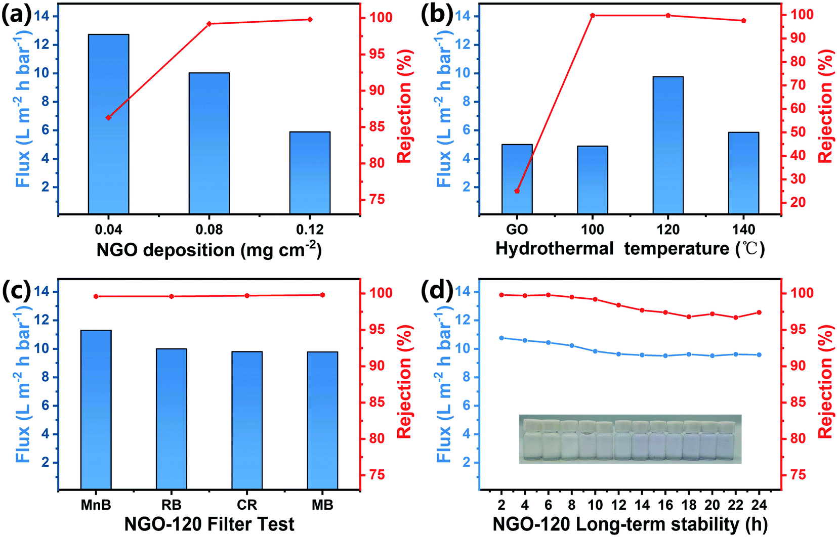 | ||
| Fig. 5 Dye filtration performance test of NGO-x membrane. (a) The filtration performance test of NGO-120 membrane with different loadings on MB solution, (b) the separation performance of NGO-x membrane on MB solution, (c) the filtration test of NGO-120 membrane for different dye solutions and (d) the long-term filtration stability of MB solutions. | ||
The test results also correspond to the characterization results above. The reduction degree, interlamellar spacing, defect degree and nitrogen doping amount of NGO can be controlled by adjusting the reaction temperature. Among them, NGO-120 with the highest nitrogen and pyridine N has the best filtration performance, indicating that pyridine N can effectively improve the filtration of NGO membranes performance. Therefore, filtration tests were performed on various organic dyes on NGO-120 to test the universality of the membrane rejection effect. As shown in Fig. 5c, the flux order of the four negative dyes (MnB, RB, CR and MB) was: MnB > CR > RB > MB, which showed opposite of molecular weight. Larger dye molecules were more readily to accumulate between the NGO sheets to obstructing the channels of water molecules, so the flux is reduced. However, the overall interception rate remained at around 99%. Generally speaking, NGO films have excellent retention properties for these dye molecules. Fig. 5d showed the long-term performance of the membrane by an uninterrupted 24 h test. The dye rejection rate kept over 97% during the test with high water flux, suggesting that the membrane has a long life span that could be suitable for the actual membrane applications.
As shown in Fig. S7,† the GO film was volatile, most of it dissolved after 7 days and completely dissolved after 14 days, implying after water molecules diffused into the intervals between GO nanosheets, they form hydrogen bonds with oxygen-containing functional groups and expand, so the GO film cannot remain stable in water.41 However, the NGO-120 film did not separate from the substrate during the long-term test of 14 days (a)–(f), indicating that the NGO-120 after nitrogen doping treatment was comparatively steady in water. In addition, the oxygen content of NGO-120 decreased after 120 °C hydrothermal process, while the π–π interplay in the graphite domain increased, enhancing the stability of the NGO-120 film in water with a wide range of pH values.42 In the SEM observation, it was found that there was no obvious change between the membrane after immersion in pure water (Fig. 6h) and the membrane before immersion (Fig. 2c). Compared with the image soaked in pure water (Fig. 6h), the folds of the membrane soaked in pH = 1 solution (Fig. 6g) were reduced. In contrast, after soaking in pH = 14 solution, the film (Fig. 6i) folds more obviously. This is because there are still negatively charged oxygen-containing functional groups on NGO-120, and at pH = 1, the surface is denser due to the attraction of a large amount of H+, while the repulsion of a large amount of OH− in the solution of pH = 14 increases the wrinkles.43 However, changes in ambient pH did not disrupt membrane integrity. It was also proved that the introduction of positively charged nitrogen-containing functional groups effectively limited the pH sensitivity of the membrane due to oxygen-containing functional groups, resulting in a broad pH stability of the membrane.44
 | ||
| Fig. 6 Digital photography of the stability of (a–f) NGO-120 membranes in aqueous solutions with different pH values and (g–i) SEM images of surfaces to NGO-120. The stability of the membrane was compared by immersing the GO and NGO-120 membranes in different pH solutions (pH = 1: HCl, 0.1 mol L; pH = 14: NaOH, 1 mol L−1) for 14 days. | ||
4. Conclusion
In summary, GO was reduced and doped with nitrogen by hydrothermal treatment at different temperature, adjusting the degree of reduction and nitrogen doping. The obtained NGO films were attached to a PVDF substrate by vacuum filtration. Under the optimized preparation conditions, the NGO-120 membranes showed high water permeability and water repellency to dye molecules, including MB, RB, CR and MnB. The pyridine N in nitrogen doping could improve the screening performance of the membrane according to its size repulsion and electrostatic interaction. Therefore, by controlling the hydrothermal temperature, it is easy to obtain a NGO film with excellent dye separation performance. This work supplies a harmless and convenient method for the preparation of NGO separation membranes.Conflicts of interest
There are no conflicts to declare.Acknowledgements
This research was supported by the National Natural Science Foundation of China (22171266), FJIRSM & IUE Joint Research Fund (no RHZX-2019-002) and the STS project (KFJ-STS-QYZD-2021-09-002).References
- Y. H. Teow and A. W. Mohammad, Desalination, 2019, 451, 2–17 CrossRef CAS.
- G. P. Liu, W. Q. Jin and N. P. Xu, Angew. Chem., Int. Ed., 2016, 55, 13384–13397 CrossRef CAS PubMed.
- L. A. Nie, C. Y. Chuah, T. H. Bae and J. M. Lee, Adv. Funct. Mater., 2021, 31, 36 CrossRef.
- X. K. Zhang, H. Li, J. Wang, D. L. Peng, J. D. Liu and Y. T. Zhang, J. Membr. Sci., 2019, 581, 321–330 CrossRef CAS.
- P. Zhang, J. L. Gong, G. M. Zeng, B. Song, W. C. Cao, H. Y. Liu, S. Y. Huan and P. Peng, J. Membr. Sci., 2019, 574, 112–123 CrossRef CAS.
- L. W. Sun, H. B. Huang and X. S. Peng, Chem. Commun., 2013, 49, 10718–10720 RSC.
- Y. Peng, Y. Li, Y. Ban, H. Jin, W. Jiao, X. Liu and W. Yang, Science, 2014, 346, 1356–1359 CrossRef CAS PubMed.
- L. B. Li, T. Zhang, Y. F. Duan, Y. Y. Wei, C. J. Dong, L. Ding, Z. W. Qiao and H. H. Wang, J. Mater. Chem. A, 2018, 6, 11734–11742 RSC.
- G. G. Liu, H. Q. Ye, A. T. Li, C. Y. Zhu, H. Jiang, Y. Liu, K. Han and Y. H. Zhou, Carbon, 2016, 110, 56–61 CrossRef CAS.
- M. Ostwal, D. B. Shinde, X. B. Wang, I. Gadwal and Z. P. Lai, J. Membr. Sci., 2018, 550, 145–154 CrossRef CAS.
- Y. X. Gao, S. M. Yan, Y. He, Y. Fan, L. Y. Zhang, J. Ma, R. T. Hou, L. Chen and J. Y. Chen, J. Membr. Sci., 2021, 626, 12 CrossRef.
- K. C. Guan, Y. D. Jia, Y. Q. Lin, S. Y. Wang and H. Matsuyama, Nano Lett., 2021, 21, 3495–3502 CrossRef CAS PubMed.
- Y. W. Zhu, S. Murali, W. W. Cai, X. S. Li, J. W. Suk, J. R. Potts and R. S. Ruoff, Adv. Mater., 2010, 22, 3906–3924 CrossRef CAS PubMed.
- S. Park, K. S. Lee, G. Bozoklu, W. Cai, S. T. Nguyen and R. S. Ruoff, ACS Nano, 2008, 2, 572–578 CrossRef CAS PubMed.
- Y. Han, Z. Xu and C. Gao, Adv. Funct. Mater., 2013, 23, 3693–3700 CrossRef CAS.
- W. W. L. Xu, C. Fang, F. L. Zhou, Z. N. Song, Q. L. Liu, R. Qiao and M. Yu, Nano Lett., 2017, 17, 2928–2933 CrossRef CAS PubMed.
- R. K. Joshi, P. Carbone, F. C. Wang, V. G. Kravets, Y. Su, I. V. Grigorieva, H. A. Wu, A. K. Geim and R. R. Nair, Science, 2014, 343, 752–754 CrossRef CAS PubMed.
- J. Zhang, Z. Y. Li, K. Zhan, R. Q. Sun, Z. Z. Sheng, M. Wang, S. L. Wang and X. Hou, Electrophoresis, 2019, 40, 2029–2040 CrossRef CAS PubMed.
- Y. Li, W. Zhao, M. Weyland, S. Yuan, Y. Xia, H. Y. Liu, M. P. Jian, J. D. Yang, C. D. Easton, C. Selomulya and X. W. Zhang, Environ. Sci. Technol., 2019, 53, 8314–8323 CrossRef CAS PubMed.
- J. Kang, Y. Choi, J. H. Kim, E. Choi, S. E. Choi, O. Kwon and D. W. Kim, J. Membr. Sci., 2021, 618, 8 CrossRef.
- B. Mi, Science, 2014, 343, 740–742 CrossRef CAS PubMed.
- H. H. Huang, R. K. Joshi, K. K. H. De Silva, R. Badam and M. Yoshimura, J. Membr. Sci., 2019, 572, 12–19 CrossRef CAS.
- X. T. Fan, C. B. Cai, J. Gao, X. L. Han and J. D. Li, Sep. Purif. Technol., 2020, 241, 8 CrossRef.
- J. H. Song, H. W. Yu, M. H. Ham and I. S. Kim, Nano Lett., 2018, 18, 5506–5513 CrossRef CAS PubMed.
- E. Yang, M. H. Ham, H. B. Park, C. M. Kim, J. H. Song and I. S. Kim, J. Membr. Sci., 2018, 547, 73–79 CrossRef CAS.
- Y. Zhang, G. W. Wen, P. Gao, S. F. Bi, X. F. Tang and D. Wang, Electrochim. Acta, 2016, 221, 167–176 CrossRef CAS.
- H. Zhang, T. Kuila, N. H. Kim, D. S. Yu and J. H. Lee, Carbon, 2014, 69, 66–78 CrossRef CAS.
- R. Ramachandran, M. Saranya, V. Velmurugan, B. P. C. Raghupathy, S. K. Jeong and A. N. Grace, Appl. Energy, 2015, 153, 22–31 CrossRef CAS.
- H. W. Hu, C. C. K. Allan, J. H. Li, Y. Y. Kong, X. W. Wang, J. H. Xin and H. Hu, Nano Res., 2014, 7, 418–433 CrossRef CAS.
- Z. J. Jiang, Z. Q. Jiang and W. H. Chen, J. Power Sources, 2014, 251, 55–65 CrossRef CAS.
- L. Liu, S. M. Ryu, M. R. Tomasik, E. Stolyarova, N. Jung, M. S. Hybertsen, M. L. Steigerwald, L. E. Brus and G. W. Flynn, Nano Lett., 2008, 8, 1965–1970 CrossRef CAS PubMed.
- Q. Li, W. L. Zhu, J. J. Fu, H. Y. Zhang, G. Wu and S. H. Sun, Nano Energy, 2016, 24, 1–9 CrossRef CAS.
- G. X. Luo, L. Z. Liu, J. F. Zhang, G. B. Li, B. L. Wang and J. J. Zhao, ACS Appl. Mater. Interfaces, 2013, 5, 11184–11193 CrossRef CAS PubMed.
- L. F. Lai, L. W. Chen, D. Zhan, L. Sun, J. P. Liu, S. H. Lim, C. K. Poh, Z. X. Shen and J. Y. Lin, Carbon, 2011, 49, 3250–3257 CrossRef CAS.
- H. L. Guo, S. Peng, J. H. Xu, Y. Q. Zhao and X. F. Kang, Sens. Actuators, B, 2014, 193, 623–629 CrossRef CAS.
- Y. C. Lin, P. Y. Teng, C. H. Yeh, M. Koshino, P. W. Chiu and K. Suenaga, Nano Lett., 2015, 15, 7408–7413 CrossRef CAS PubMed.
- R. R. Nair, H. A. Wu, P. N. Jayaram, I. V. Grigorieva and A. K. Geim, Science, 2012, 335, 442–444 CrossRef CAS PubMed.
- Q. Zhang, X. T. Qian, K. H. Thebo, H. M. Cheng and W. C. Ren, Sci. Bull., 2018, 63, 788–794 CrossRef CAS.
- S. Karan, S. Samitsu, X. Peng, K. Kurashima and I. Ichinose, Science, 2012, 335, 444–447 CrossRef CAS PubMed.
- J. Y. Chong, B. Wang, C. Mattevi and K. Li, J. Membr. Sci., 2018, 549, 385–392 CrossRef CAS.
- Y. Zhang, S. Zhang and T. S. Chung, Environ. Sci. Technol., 2015, 49, 10235–10242 CrossRef CAS PubMed.
- Y. H. Cho, H. W. Kim, H. D. Lee, J. E. Shin, B. M. Yoo and H. B. Park, J. Membr. Sci., 2017, 544, 425–435 CrossRef CAS.
- H. Huang, Y. Mao, Y. Ying, Y. Liu, L. Sun and X. Peng, Chem. Commun., 2013, 49, 5963–5965 RSC.
- Z. Cai, R. Remadevi, M. Faruque, M. Setty and M. Naebe, RSC Adv., 2019, 9, 34076–34085 RSC.
Footnote |
| † Electronic supplementary information (ESI) available. See DOI: 10.1039/d2ra00725h |
| This journal is © The Royal Society of Chemistry 2022 |