DOI:
10.1039/D2RA00265E
(Paper)
RSC Adv., 2022,
12, 7883-7891
Tunable multicolor and bright white emission in PEG modified β-NaGdF4 nanocrystals by systematic introduction of Ce3+ and Mn2+/Ln3+†
Received
14th January 2022
, Accepted 3rd March 2022
First published on 14th March 2022
Abstract
In this paper, Mn2+/Ln3+-doped hexagonal phase (β-) NaGdF4:Ce (Ln = Tb, Dy, Eu) nanomaterials with subtly tuned multicolor output have been successfully synthesized by a typical simple hydrothermal method using polyethylene glycol (PEG) as a surface modifying agent. The crystal structures, morphology, luminescence performance, and energy transfer (ET) mechanism of the synthesized NaGdF4 nanoparticles (NPs) were investigated in detail. It is found that due to the effective ET between Ce3+ and Mn2+/Ln3+, the multicolor down-conversion (DC) emission phosphors can yield three major emission bands in the visible region including blue, green and red. Moreover, the white emission could be realized through manipulating the doping ratio of Ce3+, Dy3+ and Eu3+ with suitable concentration in β-NaGdF4 NPs through effective resonance-type ET under the irradiation of 273 nm. And the corresponding CIE1931 coordinates were calculated to be (0.31, 0.32), which is near the normative white emission (0.33, 0.33). All the multicolor tuning and white emission results evidently suggest that the present Ce3+ and Mn2+/Ln3+-doped β-NaGdF4 NPs are feasible phosphors for potential applications in white-light emitters, full-color displays and photonic devices.
1. Introduction
Features including color output, narrow emission peaks, and long fluorescence of lanthanide (Ln)-doped NPs have attracted much attention for their extensive applications in many fields, like as biological labels/images, drug delivery and light emitting devices.1–8 During the past decades, the rare-earth (RE) ion doped fluorides have been used as wonderful host materials for both upconversion (UC) and DC have conceivable advantages over the conventional oxide materials because of their unique merits such as longer lifetime, higher light emission and lower phonon energy.9–14 Among the RE fluoride nanomaterials, Ln-doped NaGdF4 NPs with excellent optical and magnetic properties have been widely studied.15–19 On the one hand, NaGdF4 can act as an ideal host material due to Gd ions playing a crucial part in the ET mechanism serving as a bridge between the Ln3+ ions, consequently facilitating the ET process.20,21 Moreover, Ln-doped NaGdF4 NPs could show efficient DC emission excited by ultraviolet (UV) light when doping with Tb, Eu or Dy, while doping with another Ln3+ ion (e.g. Yb, Er, Tm) shows bright UC emission under the near-infrared excitation at 980 nm.19,22,23 Based on the special merits, dual-mode fluorescent emission of Ln-doped NaGdF4 NPs with core/shell structures have been synthesized reasonably by many researchers.16,17,24 For example, Chen's group has proposed a protocol to fabricate UC and DC dual-mode luminescent NaGdF4 NPs, which are composed of core (NaGdF4:Yb3+, Tm3+) and shell (NaGdF4:Eu3+).25 Furthermore, the seven unpaired electrons of Gd can produce the large magnetic dipole moment, which has ensured the materials containing Gd element could serve as the excellent agents in magnetic resonance image (MRI).26,27 Li's team successfully synthesized Tm3+/Yb3+/Er3+ co-doped NaGdF4 NPs applied as MRI contrast agents.17 Since multifarious researchers have done excellent works on the NaGdF4 host because of such many unexceptionable merits mentioned all above.28–32 However, it is still meaningful to explore an effective and facile approach to synthesize hydrophilic NaGdF4 NPs doping with Mn2+ and Ln3+ for multicolor tunable emission, especially for white emission.
In this paper, the tunable DC luminescent NaGdF4:Ce/Mn and Ce/Ln NPs (Ln = Tb, Eu, Dy) with PEG modified were successfully synthesized and the optical properties were studied in detail. The crystalline phase and morphology size of the as-prepared samples were successfully characterized, respectively. What's more, the luminescence properties including excitation/emission spectra of different Mn2+ and Ln3+ doping NaGdF4:Ce NPs were systematically demonstrated. Besides, the ET mechanism between Ce3+ and Mn2+/Ln3+ in NaGdF4 NPs was further discussed in detail. The doughty DC emission including the white emission of NaGdF4:Ce/Mn and Ce/Ln NPs not only provides an efficient way to get any colors but also proposes a general route for the development of DC white light applied in lighting and displays fields.
2. Experimental
2.1 Chemicals and materials
The RECl3·6H2O (RE = Gd, Ce, Tb, Dy, Eu) was purchased from Sigma-Aldrich. PEG (average molecular = 6000), ethylene glycol (EG, 99%), NaOH, MnCl2 and NaF were purchased through Sinopharm Chemical Reagent Co., China.
2.2 Preparation of Mn2+/Ln3+ doped NaGdF4:Ce NPs
A series of water-soluble Ce3+/Mn2+ and Ce3+/Ln3+-doped (L = Tb, Dy, Eu) β-NaGdF4 NPs were synthesized by a facile one-pot hydrothermal procedure using PEG as stabilization agents.33 In a typical procedure, 1 g of PEG was firstly added in 100 mL beaker containing 15 mL of EG under vigorously stirring and heated properly. Following, a total amount (1 mmol) of LnCl3 and/or MnCl2 with logically designed molar ratio was added into the mixture under continuous magnetic stirring for thirty minutes. 5 mL of EG was added again and followed by 4 mmol of NaF was added under the agitation. Twenty minutes later, the resulting solution was transferred into Teflon-lined autoclave. And then the system was maintained reaction at 200 °C for 12 hours. The as-prepared samples were washed with de-ionized water and absolute ethyl alcohol three times in sequence to remove PEG and other remnants, and obtained after separating by centrifugation with 8000 rpm.
2.3 Materials characterization
The phase structure of the synthetic β-NaGdF4:20% Ce3+/1% Mn2+ and β-NaGdF4:20% Ce3+/1% Eu3+ NPs were characterized by the X-ray powder diffraction (XRD) performed. The morphology, microstructure and chemical constitution of the synthetic samples were recorded by TEM (FEI, Tecnai F20) instrument. The Fourier transform infrared (FTIR) of surface ligands grafting on the β-NaGdF4 NPs was detected via FTIR spectra using a Magna 760 spectrometer (Nicolet). The DC excitation/emission spectra of the samples were examined by the Zolix spectrometers (fluoroSENS 9000A). The digital photographs of multicolor emission of the as-prepared powders were recorded by a Canon digital camera at room temperature.
3. Results and discussion
3.1 Morphology and microstructure
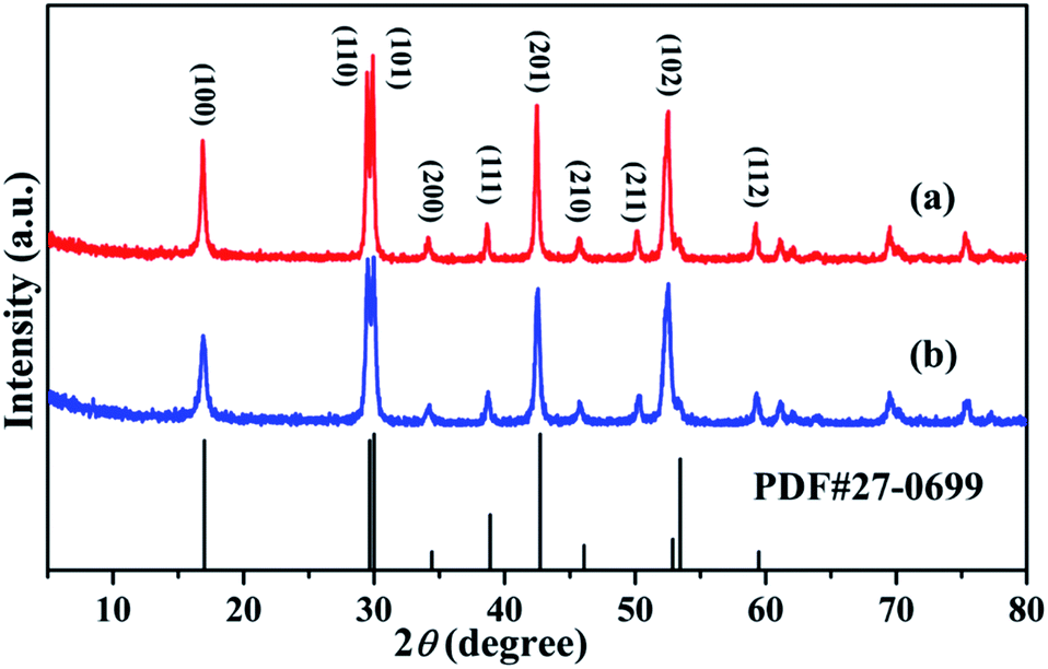
The high-quality of β-NaGdF4:Ce NPs were synthesized with different ratio of Mn2+/Ln3+ doping at the same condition. Fig. 1 shows the typical XRD patterns of the two representative as-prepared 1% Mn2+ and 1% Eu3+ doped NaGdF4:20% Ce3+ NPs, respectively. The strong and sharp diffraction peaks of the synthetic NPs, as shown in the Fig. 1, can be exactly assigned to the pure β-NaGdF4 with the standard XRD pattern (JCPDS file number: 27-0699). No other impurity diffraction peaks have examined in the XRD patterns, indicating that the pure phase and high crystalline of the NaGdF4 NPs could be obtained via hydrothermal method at low temperature (200 °C). With further increasing the contents of Mn2+ to 5% and 10%, the crystal phase of the as-prepared NPs was still matched well with hexagonal phase structure (Fig. S1†). In addition, the pure hexagonal phase NaGdF4 has a space group of P6 and refined cell parameters of a = b = 6.020 Å, c = 3.601 Å, V = 113.02 Å3 and Z = 1.5, which were essential and important factors in further investigates the multicolor performance and ET mechanism of Ce2+/Mn2+ and Ce3+/Ln3+ doped in the NaGdF4 NPs.
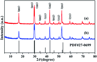 |
| | Fig. 1 The XRD patterns of (a) 1% Mn2+ and (b) 1% Eu3+ doping of NaGdF4:20% Ce3+ NPs and the standard card of hexagonal phase NaGdF4 crystal (JCPDS no. 27-0699). | |
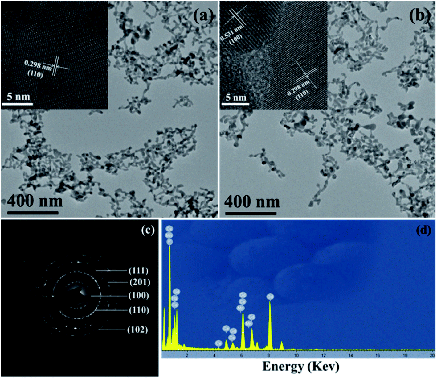
The morphologies of the prepared β-NaGdF4:20% Ce3+/1% Mn2+ and NaGdF4:20% Ce3+/1% Eu3+ NPs were illustrated by the TEM assay. As shown in the Fig. 2a and b, the as-prepared NaGdF4 NPs present uniform near-spherical structure and no other impurity nanostructure were observed. The size distribution based on the TEM image (Fig. 1a) was measured to be about 34.7 ± 3.43 nm (Fig. S2†). To further disclose the structure of the two obtained NPs, the distance between the adjacent lattice fringes with a measured d-spacing of 0.298 nm (inset of Fig. 2a) was observed, which is well matched with the plane (110) of β-NaGdF4. While the inset image in the Fig. 2b shows the lattice distance of 0.531 nm, which is corresponding to d-spacing for the (100) plane of the β-NaGdF4 structure. In addition, the obvious lattice fringes in high resolution TEM (HRTEM) images confirm the high crystallinity of the synthetic samples and also corroborate these ions doping having no influence on the phase of NaGdF4 NPs. The surface functionalization of the NaGdF4 NPs was recorded by FTIR spectrum (Fig. S3†). The peaks centered at 3454, 2896, 1651, 1513, and 1091 cm−1 are corresponded to O–H, –CH2, C–O, –COO−, C–O–C, respectively, indicating the PEG successful coating on the surface of the NaGdF4 NPs. Furthermore, the selected area electron diffraction (SAED) in the Fig. 2c clearly presents the intense diffraction fringes, which could be ascribed to the specific (102), (201), (111), (110) and (100) planes of the β-NaGdF4, also coincided well with the former XRD analysis results. To confirm the comprise elements of the DC samples, the typical EDS spectrum of 20% Ce3+ and 1% Mn2+ doped β-NaGdF4 NPs were carried out. The result reveals that the as-prepared NPs are principally composed of Cu, C, Gd, Ce, Mn, Na and F elements, indicating that the Mn2+ and Ce3+ were successfully doped into the NaGdF4 host. Note that the signals of Cu and C are resulting from copper grid and the carbon film on the supporting copper, respectively.
 |
| | Fig. 2 TEM and HRTEM images of (a) 1% Mn2+ and (b) 1% Eu3+ doping β-NaGdF4:20% Ce3+ NPs. (c) The SAED pattern of the sample of (a). (d) Typical EDS spectrum of β-NaGdF4:20% Ce3+/1% Mn2+ samples. | |
3.2 Optical properties and ET mechanism
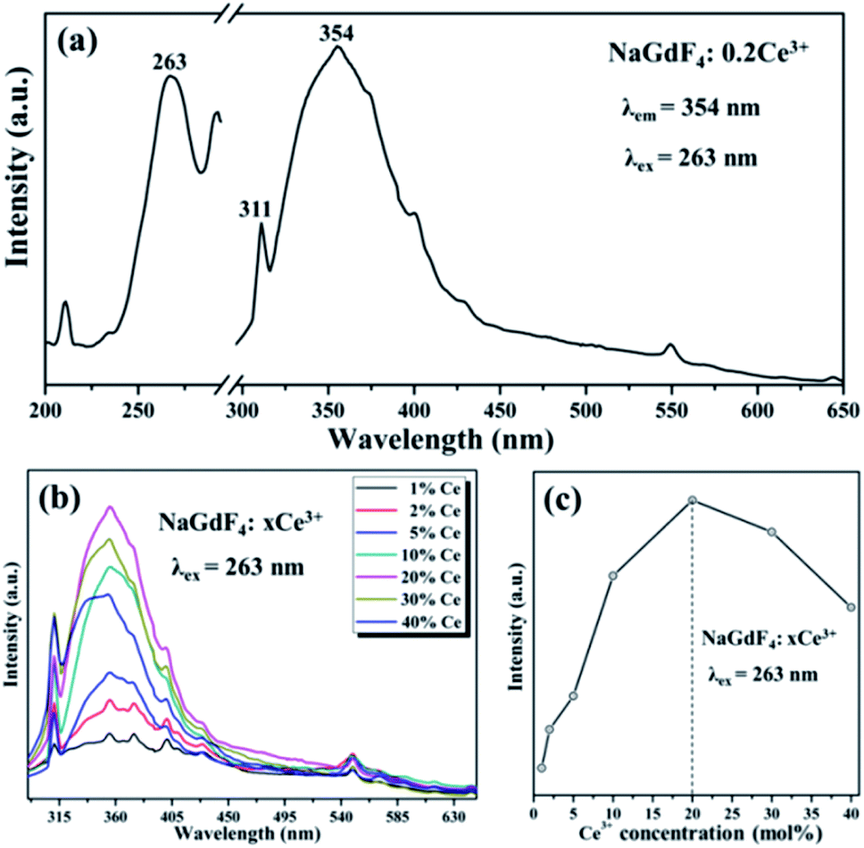
To reveal the DC emission properties of the preparative samples, the DC excitation and emission spectra were systematically recorded. Fig. 3 shows the PL properties of only Ce3+ doped in NaGdF4 NPs. The excitation spectrum of NaGdF4:20% Ce3+ samples monitored at 354 nm shows a strong broad band at 263 nm because of the lowest Ce3+ 4f → 5d transition (left of Fig. 3a).34 The emission spectrum was recorded under the excitation wavelength at 263 nm at room temperature, obviously with a wave band ranging from 305 nm to 450 nm including the maximum at about 354 nm and the sharp line at about 311 nm. The maximum and sharp peaks were due to energy efficient transition from the 5d1 to 4f1 of Ce3+ and 6P7/2 → 8S7/2 electron transition of Gd3+, respectively (right of Fig. 3a). The relative emission intensities in NaGdF4 NPs can be precisely changed by tuning the sensitizer doping concentration. By adjusting the different Ce3+ (from 1 to 40 mol%) concentrations, the optimum doping concentration of Ce3+ in β-NaGdF4 can be precisely obtained. As shown in Fig. 3b, Ce3+ doped NaGdF4 NPs exhibits the almost same emission peeks but different emission intensity with varying Ce3+ doping concentration. It is worth noting that the PL emission intensity remarkably enhanced firstly and then decreased with a further increase of doping concentration, reaching a maximum at 20% of Ce3+ doping concentration under excited at 263 nm. The emission intensity changes with variations of Ce3+ are directly observed from Fig. 3c.
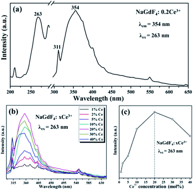 |
| | Fig. 3 (a) Excitation and emission spectrum of the NaGdF4:20% Ce3+ sample. (b) Emission spectra of the NaGdF4:xCe3+ (x = 1, 2, 5, 10, 20, 30 and 40 mol%) NPs. (c) PL intensity of NaGdF4:xCe3+ samples with the Ce3+ concentration. | |
The results demonstrated that the optimum doping concentration of Ce3+ would be 20% in the NaGdF4 host on account of the concentration quenching effect.35 Therefore, based on the Blasse's report, the critical distance (RC) of Ce3+ ions in NaGdF4 host could be calculated by the concentration quenching method:36
| |
 | (1) |
where
V,
N and
XC are the volume, number of host cations and optimum concentration of doped ions of the unit cell, respectively. All of above parameters of Ce
3+ in the NaGdF
4 host are as follows,
V = 113.02 Å
3,
N = 1.5 and
XC = 0.2; therefore,
RC is about 8.96 Å calculated by using
eqn (1).
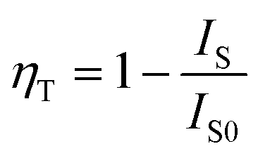
To further invested the ET mechanism among Ce3+ and Mn2+/Tb3+/Eu3+/Dy3+ in NaGdF4 host, the PL emission performance of Mn2+/Tb3+/Eu3+/Dy3+ co-/doped NaGdF4:20% Ce NPs have been studied, respectively. The various excitation/emission spectra of the NaGdF4:20% Ce with a variety of Mn2+ doping concentration turning from 0 to 10 mol% were monitored at 542 nm and excited by 263 nm UV light, respectively. As demonstrated in the Fig. 4a, the excitation spectra show peeks range from 230 nm to 310 nm and reach a maximum value at 263 nm, which is ascribed to the 4f → 5d electron transition of Ce3+. The emission spectra of different Mn2+ with fixed Ce3+(20%) co-doped NaGdF4 (Fig. 4b) show the broad emission band were centered at 354 nm and 538 nm, which are respectively attributed to the electrons transition with 5d1 → 4f1 of Ce3+ and 4T1 → 6A1 of Mn2+, respectively.37 Note that, the sharp peak (311 nm) resulting from 6P7/2 → 8S7/2 transitions of Gd3+ was continuously decreased with the augment of Mn2+ concentration under the excitation, indicating that the effective ET between Gd3+ and Mn2+ was exist in NaGdF4 host. Moreover, the emission intensity of Ce3+ was continuously decreased, while the intensity of Mn2+ emission increased firstly and then decreased with the increase of Mn2+ concentration. The corresponding PL emission intensity of the NaGdF4:20% Ce3+/Mn2+ system was shown in the Fig. 4c. The initial Mn2+ emission intensity increase demonstrates an effectual ET between Ce3+ and Mn2+, while the latter decrease was because of the concentration quenching effect in the NaGdF4:20% Ce3+/Mn2+ system.38 And the ET efficiency (ηT) could be estimated by the followed formula:39
| |
 | (2) |
where
ηT is ET efficiency between Ce
3+ and Mn
2+.
IS and
IS0 are the PL intensity of a sensitizer (Ce
3+) doped with and without of an activator (Mn
2+), respectively. The
ηT value curve of different Mn
2+ concentration doped NaGdF
4:20% Ce calculated by
eqn (2) was fitted using a bi-exponential function. The calculated results presented in the
Fig. 4d, which clearly revel that the
ηT was increase rapidly and then slow down gradually and the maximum can reach to 63% with the continuing Mn
2+ concentration increase under the 263 nm excitation. The
ηT value further demonstrates the efficient ET from Ce
3+ to Mn
2+ in NaGdF
4 system. The possible ET mechanism of the NaGdF
4:20% Ce
3+/Mn
2+ was shown in the
Fig. 5. The
RC between Ce
3+ and Mn
2+ ions also could be estimated by the concentration quenching method mentioned in
eqn (1). The difference is that
XC is the critical total concentration of rare earth ions including Ce
3+ and Mn
2+. Therefore, the ET
RC between the Ce
3+ and Mn
2+ is about 30.66 Å based on concentration quenching
eqn (1) when
XC equals 0.005, which is larger than 4 Å, revealing that the ET mechanism of Ce
3+ and Mn
2+ ions is maybe multipolar interaction.
37
 |
| | Fig. 4 (a) Excitation and (b) emission spectra of NaGdF4:20% Ce3+/xMn2+ (x = 0.1, 0.5, 1, 2, 5 and 10 mol%) samples. (c) The PL intensity curves of NaGdF4:Ce3+/Mn2+ samples monitored at 354 nm of Ce3+ emission and 538 nm of Mn2+ emission as a function of the Mn2+ doping concentration. (d) ET efficiency from Ce3+ to Mn2+ in NaGdF4:20% Ce3+/xMn2+ samples. | |
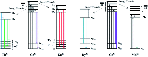 |
| | Fig. 5 The proposed ET mechanism for Ce3+/Tb3+, Ce3+/Eu3+, Ce3+/Dy3+ and Ce3+/Mn2+ in the NaGdF4 host. | |
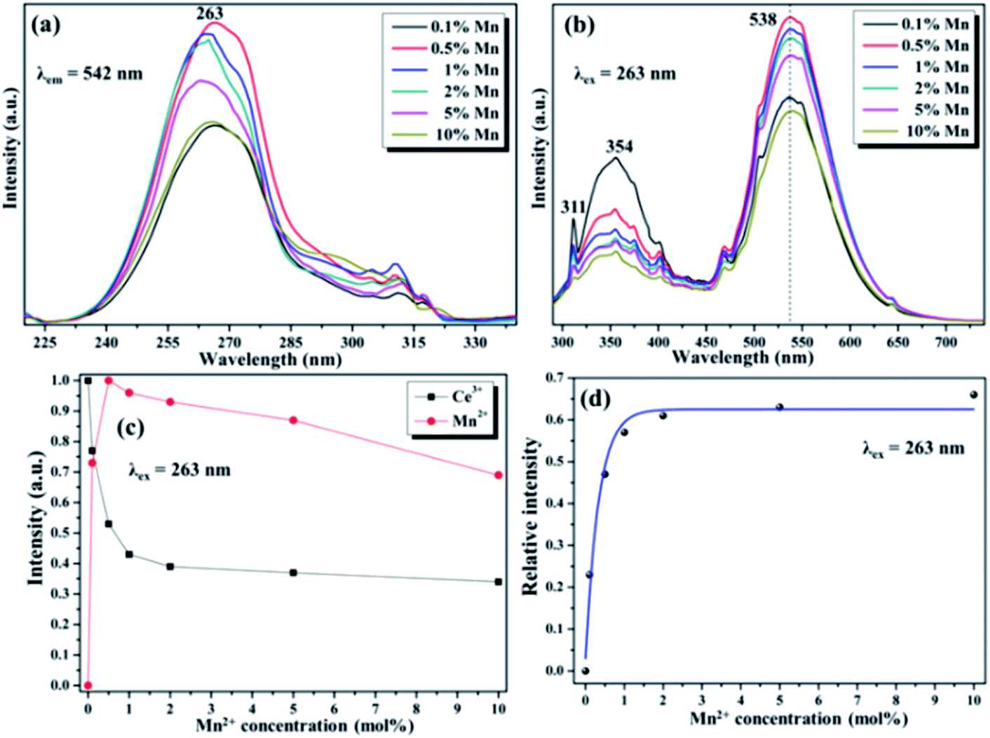
The fluorescence results of Ce3+/Tb3+, Ce3+/Dy3+ and Ce3+/Eu3+ doped in NaGdF4 host based on the similar ET mechanism were shown in the Fig. 6, 7 and 8, respectively. Fig. 6a and b detailly illustrate the excitation/emission spectra of Ce/Tb co-doped NaGdF4 host, which strongly indicate that the existence of ET from Ce3+ to Tb3+. The typical emission peaks at 380 nm, 489 nm, 542 nm, 584 nm and 620 nm, which are respectively attributed to the 5D3 → 7F6 and 5D4 → 7FJ (J = 6, 5, 4, 3) electron transitions of Tb3+.37 The possible ET mechanism between Ce3+ and Tb3+ were also shown in the Fig. 5. The corresponding PL emission intensity of Ce3+ and Tb3+ in the NaGdF4 host was demonstrated in the Fig. 6c. It is clearly present that the intensity of emission band (300–400 nm) of Ce3+ was decreasing all the way while the emission intensity of Tb3+ increased at first and then decreased with the continuous increase of Tb3+. The change of PL intensity of Ce3+ and Tb3+ directly illustrates the efficient ET from Ce3+ to Tb3+ in NaGdF4 host. The ET efficiency (ηT) was calculated by eqn (2), the maximum value of ηT is about 94% as represented in the Fig. 6d. The ET RC between Ce3+ and Tb3+ is computed to be 9.86 Å larger than 4 Å, indicating that the ET mechanism from Ce3+ to Tb3+ ions is also multipolar interaction.40
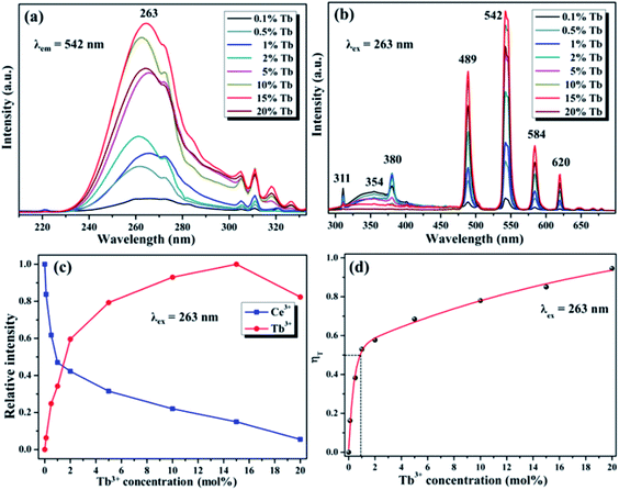 |
| | Fig. 6 (a) Excitation and (b) emission spectra of the NaGdF4:20% Ce3+/xTb3+ (x = 0.1, 0.5, 1, 2, 5, 10, 15 and 20 mol%) samples. (c) PL intensity curves of NaGdF4:Ce3+/Tb3+ samples monitored at 354 nm of Ce3+ emission and 542 nm of Tb3+ emission variation curve with the Tb3+ doping. (d) ET efficiency from Ce3+ to Tb3+ in NaGdF4 host. | |
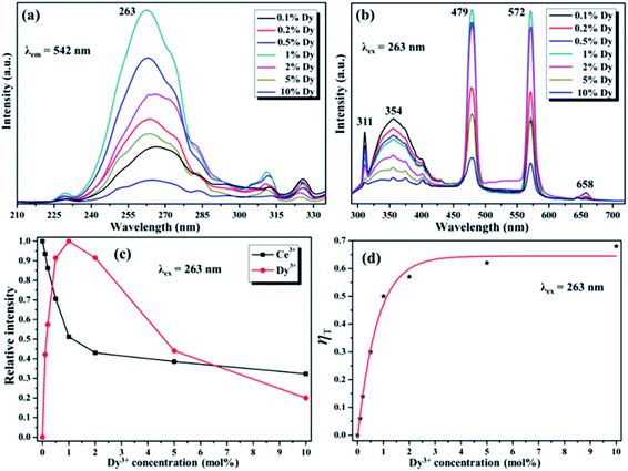 |
| | Fig. 7 (a) Excitation and (b) emission spectra of the NaGdF4:20% Ce3+/xDy3+ (x = 0.1, 0.2, 0.5, 1, 2, 5 and 10 mol%) samples. (c) PL intensity curves of NaGdF4:20% Ce3+/xDy3+ samples monitored at 354 nm of Ce3+ emission and 572 nm of Dy3+ emission as a function of the Dy3+ doping concentration. (d) ET efficiency from Ce3+ to Dy3+ in NaGdF4 host. | |
 |
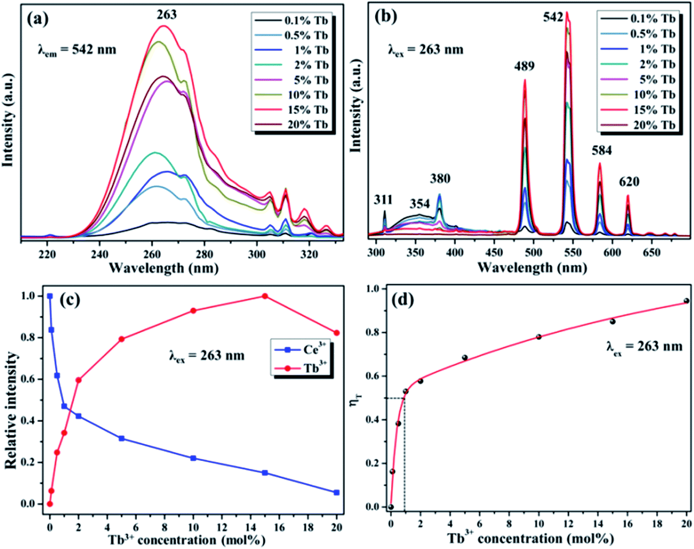
| | Fig. 8 (a) Excitation and (b) emission spectra of 20% Ce3+/xEu3+ (x = 0.5, 1, 2, 5, 10 and 15 mol%) NaGdF4 samples. (c) PL intensity curves of NaGdF4:20% Ce3+/xTb3+ samples monitored at 354 nm of Ce3+ emission and 615 nm of Eu3+ emission as a function of the Eu3+ doping concentration. (d) ET efficiency from Ce3+ to Eu3+ in NaGdF4 samples. | |
Fig. 7a and b demonstrate the excitation/emission spectra of Ce/Dy co-doped in NaGdF4 NPs. As shown in the Fig. 7b, the emblematic emission peaks at 479 nm and 512 nm are appeared, which is due to the electron transitions of 4F9/2 → 6H15/2 and 4F9/2 → 6H13/2 of Dy3+. Fig. 5 also shows the corresponding ET mechanism among Ce3+ and Dy3+. From the PL intensity of Ce3+/Dy3+ in the Fig. 7c, it can be seen that the intensity of Ce3+ and Dy3+ emission is obviously different. The intensity of Ce3+ emission was decreased but that of Dy3+ emission was increased firstly. With the continue increase of doping concentration of Dy3+, the intensity of Ce3+ emission was still decreased while Dy3+ emission is decrease on the contrary. All of the results strongly validate the effective ET from the Ce3+ to Dy3+ in NaGdF4 NPs. The value of ηT calculated by eqn (2) were shown in the Fig. 7d and the maximum is about 65%. The RC of ET from the Ce3+ to Dy3+ estimated using eqn (1) is about 24.32 Å when XC equals 0.01.
Fig. 8a demonstrates the excitation spectra of NaGdF4:20% Ce/Eu NPs and the corresponding emission spectra was shown in the Fig. 8b. The representative emission band were centered at 591 nm and 615 nm, ascribed to the 5D0 → 7F1 and 5D0 → 7F2 electron transition of Eu3+, which was combined with the corresponding ET mechanism with Ce3+ and Eu3+ in the Fig. 5. The whole PL emission results dependent on the different doping concentration of Eu3+ were performed to validate the efficient ET between Ce3+ and Eu3+. As shown in Fig. 8c and d, with continuously increasing Eu3+ concentration, the emission intensity of Ce3+ decreased while Eu3+ was increased firstly and then decreased, which may because of the concentration quenching effect. These results also indicate the resultful ET between the Ce3+ and Eu3+ in NaGdF4 NPs. The ηT was also calculated by eqn (2), the results of ηT value were shown in the Fig. 8d and the maximum is about 75%. The RC of ET from the Ce3+ to Eu3+ is determined by the concentration quenching equation to be 24.32 Å.
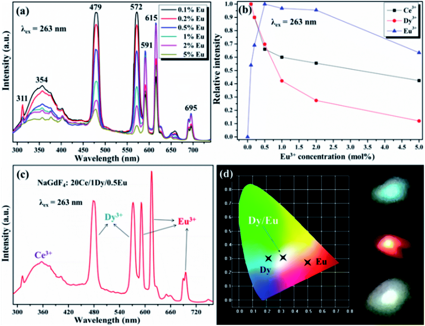
Due to the wide range-tunable emissions of Ce3+/Dy3+ and Ce3+/Eu2+ doped NaGdF4 NPs, it is reasonable to design the sensitizer (Ce3+) and activator (Dy3+, Eu3+) tri-doping NaGdF4 NPs for precisely control emission, especially for white emission. Therefore, the different doping concentration of Eu3+ in the NaGdF4:20% Ce/1% Dy NPs were further synthesized for systematic white emission research. As shown in Fig. 9a, the NaGdF4 NPs tri-doped with Ce3+/Dy3+(20/1 mol%) and Eu (x mol%) exhibit the characteristic sharp emission peaks corresponded to the green, blue and red emissions, which can be attributed to the efficient emission of Ce3+, Dy3+ and Eu3+. With the continuous increase doping of Eu3+, the emission intensity of Ce3+ and Dy3+ ions was always decreased, while the emission intensity of Eu3+ can reach the maximum at the concentration of 0.5% (Fig. 9b). It can be proved that the efficient ET between Ce3+ and Eu3+ ions is more significant at the coexistence of Dy3+/Eu3+. According to the calculation of emission spectrum data by using the color coordinate calculation soft-ware, the color of the emission light is closest to white when the Eu3+ ion doping concentration is 0.5 mmol%. The corresponding emissive spectrum is obviously exhibited in the Fig. 9c. Fig. 9d shows the color coordinate diagram of Dy3+ and Eu3+ single and co-doped in NaGdF4:20% Ce host and the corresponding luminescence photos are demonstrated on the right. It can be clearly seen that the white emission of NaGdF4:20% Ce NPs is successfully realized when doping with 1% Dy3+ and 0.5% Eu3+. The CIE chromaticity coordinates were computed about (0.31, 0.32) according to the emission spectrum, which is near closely to the standard white emission (0.33, 0.33).
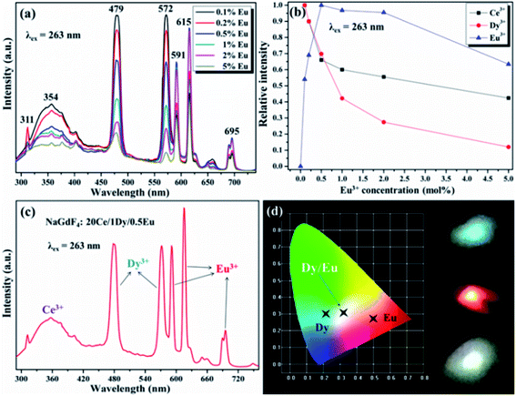 |
| | Fig. 9 (a) Emission spectra of the NaGdF4:20% Ce3+/1% Dy3+/xEu3+ (x = 0.1, 0.2, 0.5, 1, 2 and 5%) samples. (b) The corresponding PL intensity curves of NaGdF4:20% Ce3+/1% Dy3+/xEu3+ samples monitored at 354 nm of Ce3+ emission, 572 nm of Dy3+ emission and 615 nm of Eu3+ emission as a function of the Eu3+ doping concentration. (c) Emission spectrum of the NaGdF4:20% Ce3+/1% Dy3+/0.5% Eu3+ samples. (d) CIE chromaticity diagram of NaGdF4:20% Ce3+ NPs doped with 1% Dy3+, 1% Eu3+ and 1% Dy3+/0.5% Eu3+, the insets are corresponding photographs of these NPs under 263 nm UV light. | |
4. Conclusion
In summary, a series of hydrophilic NaGdF4:Ce/Mn and Ce/Ln (Ln = Tb, Dy, Eu) NPs with multicolor tunable emission have been successfully fabricated. The morphology studied displays the successful manufacture of the high-quality NaGdF4 NPs with uniform shape, mono-dispersity and pure hexagonal phase. Through adjusting the doping ions and content, the relative emission intensities of various emission colors can be adjusted precisely, resulting in the multicolor emission. Furthermore, based on the acquirement of the three basic colors (blue, green and red) in the Ln-doped NaGdF4 system, the boosting white emissions could be obtained naturally with emission balance due to the effective ET from Ce3+ to Eu3+/Dy3+. It is importantly elucidated that the CIE coordinates of NaGdF4:20% Ce3+/1% Dy3+/0.5% Eu3+ NPs are seated in the white region and calculated to be (0.31, 0.32), which is near closely to the normative white light emission (0.33, 0.33). The white emission in NaGdF4 host by tri-doping Ce3+, Dy3+ and Eu3+ was achieved for the first time. The excellent DC emission, variable multicolor output and lightful white luminescence of the Mn2+/Ln3+-doped NaGdF4:Ce NPs may have potential applications in diverse fields.
Conflicts of interest
There are no conflicts to declare.
Acknowledgements
This work was supported by the National Natural Science Foundation of China (No. 52003144), and the Youth Science Foundation of Shanxi Province (No. 201901D211401).
Notes and references
- X. Qin, X. W. Liu, W. Huang, M. Bettinelli and X. G. Liu, Chem. Rev., 2017, 117, 4488–4527 CrossRef CAS PubMed.
- F. Wang and X. G. Liu, Chem. Soc. Rev., 2009, 38, 976–989 RSC.
- S. Wu, D. J. Milliron, S. Aloni, V. Altoea, D. V. Talapin, B. E. Cohen and P. J. Schuck, Proc. Natl. Acad. Sci. U. S. A., 2009, 106, 10917–10921 CrossRef CAS PubMed.
- M. An, J. Cui, Q. He and L. Wang, J. Mater. Chem. B, 2013, 1, 1333–1339 RSC.
- J. W. Stouwdam, G. A. Hebbink, J. Huskens and F. C. J. M. van Veggel, Chem. Mater., 2003, 15, 4604–4616 CrossRef CAS.
- G. A. Kumar, C. W. Chen, J. Ballato and R. E. Riman, Chem. Mater., 2007, 19, 1523–1528 CrossRef CAS.
- H. Wang, X. D. Hong, R. L. Han, J. H. Shi, Z. J. Liu, S. J. Liu, Y. Wang and Y. Gan, Sci. Rep., 2015, 5, 17088–17093 CrossRef CAS PubMed.
- F. Wang, D. Banerjee, Y. S. Liu, X. Y. Chen and X. G. Liu, Analyst, 2010, 135, 1839–1854 RSC.
- X. Bai, D. Li, Q. Liu, B. Dong, S. Xu and H. W. Song, J. Mater. Chem., 2012, 22, 24698–24704 RSC.
- F. Meiser, C. Cortez and F. Caruso, Angew. Chem., Int. Ed., 2004, 43, 5954–5957 CrossRef CAS PubMed.
- Z. L. Wang, Z. W. Quan, P. Y. Jia, C. K. Lin, Y. Luo, Y. Chen, J. Fang, W. Zhou, C. J. O' Connor and J. Lin, Chem. Mater., 2006, 18, 2030–2037 CrossRef CAS.
- F. Wang and X. G. Liu, J. Am. Chem. Soc., 2008, 130, 5642–5643 CrossRef CAS PubMed.
- C. Feldmann, M. Roming and K. Trampert, Small, 2006, 2, 1248–1250 CrossRef CAS PubMed.
- G. S. Yi, H. C. Lu, S. Y. Zhao, Y. Ge, W. J. Yang, D. P. Chen and L. H. Guo, Nano Lett., 2004, 4, 2191–2196 CrossRef CAS.
- Y. Wu, C. X. Li, D. M. Yang and J. Lin, J. Colloid Interface Sci., 2011, 354, 429–436 CrossRef CAS PubMed.
- Y. S. Liu, D. T. Tu, H. M. Zhu, R. F. Li, W. Q. Luo and X. Y. Chen, Adv. Mater., 2010, 22, 3266–3271 CrossRef CAS PubMed.
- J. Zhou, Y. Sun, X. X. Du, L. Q. Xiong, H. Hu and F. Y. Li, Biomaterials, 2010, 31, 3287–3295 CrossRef CAS PubMed.
- H. Y. Xing, S. J. Zhang, W. B. Bu, X. P. Zheng, L. J. Wang, Q. F. Xiao, D. L. Ni, J. M. Zhang, L. P. Zhou, W. J. Peng, K. L. Zhao, Y. Q. Hua and J. L. Shi, Adv. Mater., 2014, 26, 3867–3872 CrossRef CAS PubMed.
- M. He, P. Huang, C. L. Zhang, H. Y. Hu, C. C. Bao, G. Gao, R. He and D. X. Cui, Adv. Funct. Mater., 2011, 21, 4470–4477 CrossRef CAS.
- F. Wang, X. P. Fan, M. Q. Wang and Y. Zhang, Nanotechnology, 2007, 18, 025701 CrossRef.
- C. H. Liu, H. Wang, X. R. Zhang and D. P. Chen, J. Mater. Chem., 2009, 19, 489–496 RSC.
- C. Y. Liu, Z. Y. Gao, J. F. Zeng, Y. Hou, F. Fang, Y. L. Li, R. R. Qiao, L. Shen, H. Lei, W. S. Yang and M. Y. Gao, ACS Nano, 2013, 7, 7227–7240 CrossRef CAS PubMed.
- J. Li, Z. D. Hao, X. Zhang, Y. S. Luo, J. H. Zhao, S. Z. Lu, J. Cao and J. H. Zhang, J. Colloid Interface Sci., 2013, 392, 206–212 CrossRef CAS PubMed.
- Y. I. Park, J. H. Kim, K. T. Lee, K. S. Jeon, H. B. Na, J. H. Yu, H. M. Kim, N. Lee, S. H. Choi, S. I. Baik, H. Kim, S. P. Park, B. J. Park, Y. W. Kim, S. H. Lee, S. Y. Yoon, I. C. Song, W. K. Moon, Y. D. Suh and T. Hyeon, Adv. Mater., 2009, 21, 4467–4471 CrossRef CAS.
- H. S. Jang, K. Woo and K. Lim, Opt. Express, 2012, 20, 17107–17118 CrossRef CAS.
- X. W. Zhang, Z. Zhao, X. Zhang, D. B. Cordes, B. Weeks, B. Qiu, M. Kailasnath and D. K. Sardar, Nano Res., 2014, 8, 636–648 CrossRef.
- Y. Wu, D. M. Yang, X. J. Kang, C. X. Li and J. Lin, Mater. Res. Bull., 2013, 48, 2843–2849 CrossRef CAS.
- L. L. Wang, L. L. Liu, Q. Xu, T. Sun and W. N. Gu, Adv. Mater. Res., 2013, 661, 74–78 Search PubMed.
- H. X. Guan, G. X. Liu, J. X. Wang, X. T. Dong and W. S. Yu, Dalton Trans., 2014, 43, 10801–10808 RSC.
- X. Q. Zhang, X. P. Fan, X. S. Qiao and Q. Luo, Mater. Chem. Phys., 2010, 121, 274–279 CrossRef CAS.
- M. Karbowiak, A. Mech, A. Bednarkiewicz, W. Stręk and L. Kępińskib, J. Phys. Chem. Solids, 2005, 66, 1008–1019 CrossRef CAS.
- B. F. Wang, R. R. Deng, J. Wang, Q. X. Wang, Y. Han, H. M. Zhu, X. Y. Chen and X. G. Liu, Nat. Mater., 2011, 10, 968–973 CrossRef PubMed.
- S. J. Zeng, M.-K. Tsang, C.-F. Chan, K.-L. Wong and J. H. Hao, Biomaterials, 2012, 33, 9232–9238 CrossRef CAS PubMed.
- T. Q. Sheng, Z. L. Fu, X. J. Wang, S. H. Zhou, S. Y. Zhang and Z. W. Dai, J. Phys. Chem. C, 2012, 116, 19597–19603 CrossRef CAS.
- T. S. Chan, C. C. Lin, R. S. Liu, R. J. Xie, N. Hirosaki and B. M. Cheng, J. Electrochem. Soc., 2009, 156, J189–J191 CrossRef CAS.
- G. Blasse, J. Solid State Chem., 1986, 62, 207–211 CrossRef CAS.
- Y. Zhang, G. G. Li, D. L. Geng, M. M. Shang, C. Peng and J. Lin, Inorg. Chem., 2012, 51, 11655–11664 CrossRef CAS PubMed.
- G. G. Li, D. L. Geng, M. M. Shang, Y. Zhang, C. Peng, Z. Y. Cheng and J. Lin, J. Phys. Chem. C, 2011, 115, 21882–21892 CrossRef CAS.
- W. J. Yang and T. M. Chen, Appl. Phys. Lett., 2006, 88, 101903 CrossRef.
- T. W. Kuo and T. M. Chen, J. Electrochem. Soc., 2010, 157, 216–220 CrossRef.
Footnote |
| † Electronic supplementary information (ESI) available. See DOI: 10.1039/d2ra00265e |
|
| This journal is © The Royal Society of Chemistry 2022 |
Click here to see how this site uses Cookies. View our privacy policy here. 
 Open Access Article
 This Open Access Article is licensed under a Creative Commons Attribution-Non Commercial 3.0 Unported Licence
 *a,
Yaru Peia,
Ruimei Lianga,
Chao Qianb and
Jinzeng Wang*a
*a,
Yaru Peia,
Ruimei Lianga,
Chao Qianb and
Jinzeng Wang*a