 Open Access Article
Construction of a ternary system: a strategy for the rapid formation of porous poly(lactic acid) fibers
Bei Wanga,
Junyan Yao *a,
Haoyu Wangb and
Mengqi Wangb
aKey Laboratory of Macromolecular Science & Technology of Shaanxi Province, Northwestern Polytechnical University, Xi'an 710129, Shaanxi, China. E-mail: yaojunyan@nwpu.edu.cn
bSchool of Queen Mary University of London Engineering, Northwestern Polytechnical University, Xi'an 710129, Shaanxi, China
First published on 24th February 2022
Abstract
Combining electrospinning technology with nonsolvent induced phase separation (ESP-NIPS), 10 wt% poly(lactic acid) (PLA) spinning solutions are prepared by using chloroform as a good solvent and absolute ethanol as a nonsolvent. The “PLA/CHCl3/C2H5OH” ternary system is constituted to realize the rapid preparation of porous-structured PLA fibers. The morphologies, thermal properties and crystalline structures of the obtained fibers are characterized and the rapid forming mechanism of PLA porous fibers is investigated and discussed. The interaction parameters between the substances of the “PLA/CHCl3/C2H5OH” ternary system, binodal line, spinodal line and critical point are obtained by theoretical calculation and experiment, and the “PLA/CHCl3/C2H5OH” ternary phase diagram model is established. The results show that, when the mass ratio of chloroform/ethanol is around 75/25, the rapid “in situ” formation of the PLA fibers can be realized with porous structures within 5–10 s. The establishment of a “nonsolvent-solvent–polymer” ternary phase diagram model has laid a theoretical foundation for the rapid formation of polymer porous fibers by ESP-NIPS. The ESP-NIPS for the porous PLA fibers preparation provides a new resolution for the rapid formation of porous polymer materials, which is vital to further expand the application of electrospun fibers in emergency situations such as isolation, protection, insulation and flame retardant usage.
Introduction
In the past few years, polymers have been widely studied because of their large molecular weight, designable structures and easy surface functionalization. Especially in the fields related to intelligent technology such as optics and electricity, more and more polymer-based materials are used in intelligent matrix building blocks.1Fagiolari et al.2 outlined the application of poly(3,4-ethylenedioxythiophene) (PEDOT) as an ideal polymer organic conductor with excellent electrical conductivity, high flexibility, stability and low cost in the field of dye-sensitized solar cells (DSSCs). Beccatelli et al.3 demonstrated the functionalization of a commercial polyurethane (PU) foam with the conductive polymer PEDOT:PSS: the resulting material is a modified all-polymeric foam which can convert the material mechanical pressure into electrical signals. This material is a new type of pressure sensor, which can be used in the field of healthcare. Rahman et al.4 chose NaI as a simple and cheap doping salt for a chitosan biopolymer matrix, and successfully prepared chitosan-NaI electrolyte by solution casting technique. This study paves the way to the use of biopolymeric matrices for 100% solid-state DSSCs. Amici et al.5 prepared a highly cross-linked methacrylate-based polymer matrix by solvent-free, thermally induced, radical polymerization, encompassing dextrin-based nanosponges (NS) and swollen in liquid electrolyte in order to obtain a composite gel polymer electrolyte (CGPE). Results demonstrates that the use of CGPE can greatly improve the safety and performance of Li–O2 batteries. Mohaimeed et al.6 described a successfully designed simple and ultrasensitive modified metal oxide naltrexone tetraphenylborate (NTX-TPB-CuO/Al2O3) nanocomposite potentiometric sensor for the determination of naltrexone hydrochloride (NTX) in authentic powder and commercial formulations. Abdah et al.7 coated poly(3,4-ethylenedioxythiophene)/manganese oxide on porous carbon nanofibers (P-CNFs/PEDOT/MnO2) and used them as anode materials via the innovative combination of electrospinning, carbonization, and electrodeposition. The results show that the electrochemical performance of the as-prepared P-CNFs/PEDOT/MnO2 electrode is satisfactory.
Poly(lactic acid) (PLA) is a non-toxic, non-irritating biosynthetic polymer material with good biocompatibility and absorbability, biodegradability, renewability and processing properties, and can be processed into blocks, sheets and foams as well as filaments and fibers.8 Among these various structures, PLA nanofibers possess good application prospects in filter materials,9,10 biomedicine,11 tissue engineering12 and other fields due to their advantages of large specific surface area, high porosity and good fiber continuity.
Electrospinning (ESP) is an effective method to produce nano- or micro-sized polymer fibers from polymer solutions or melts.13 However, the traditional “polymer–solvent” binary spinning system has the characteristics of low fiber porosity and low preparation efficiency, which limits the application of electrospinning technology. If the rapid prototyping of fiber electrospinning could be realized, the porous fibers with “in situ” formation would be achieved, which is of significance to develop further application domain in isolation, protection, insulation or flame retardant and other emergency occasions.
In the traditional electrospinning technology, the production efficiency can be improved within a certain range by increasing the spinning speed, but the phenomenon of solidification difficulty and fiber bonding due to a large amount of solvent volatilization lagging would come out subsequently. Therefore, only increasing the spinning speed cannot improve the spinning efficiency.
Phase separation is an effective method for preparing porous membranes, which have been widely used in filtration and other fields. Nonsolvent induced phase separation (NIPS) has the advantage of easy-controlling14 and is mainly used for the template-free process of producing polymer foams and films.8
Since NIPS can promote the segregation of polymers and form compact porous membranes, the electrospinning method and the nonsolvent induced phase separation method can be combined in order to achieve the purpose of rapid solution spinning of polymers.
Wannatong et al.15 investigated the effects of solvent properties on the productivity and morphology of polystyrene (PS) electrospun nanofibers. Fiber diameter was found to decrease with increasing solvent density and boiling point. Large differences between PS and solvent solubility parameters was responsible for the bead-on-string morphology observed. In addition, the productivity of nanofibers was gradually increased with increasing dielectric constant and dipole moment of the solvent during electrospinning.
Katsogiannis et al.14 produced porous electrospun polycaprolactone (PCL) fibers in different solvent systems through a nonsolvent induced phase separation mechanism. The effect of the morphology of PCL fibers under different good/poor solvent ratios was studied. The pore formation was favoured at high good/poor solvent ratios.
R. Casasola et al.16 studied the effect of different solvent systems on the morphology and diameter of electrospun PLA nanofibers by preparing PLA solutions in various pure solvents and binary solvent systems. The results show that nanofibers with different morphologies (beaded fibers, defect-free fibers, etc.) can be obtained by adjusting the polymer concentration in the spinning solution, the surface tension of the spinning solution, and the electrical conductivity. Furthermore, in the binary solvent system, the diameter of the nanofibers decreases with the increase of the boiling point of the second solvent in the system.
Previous studies mostly focused on the effect of solvent on fiber morphology and properties in electrospinning or phase separation systems. The process of fiber preparation was slow. In this study, the electrospinning-nonsolvent induced phase separation (ESP-NIPS) is applied to construct porous fibers, where PLA is used as electrospun matrix material, chloroform and absolute ethanol are good solvent and nonsolvent, respectively. Chloroform is a good solvent for PLA with high volatility at room temperature, which is easy to prepare PLA electrospun fibers. The reason for choosing absolute ethanol as a non-solvent is that the volatility of ethanol is between chloroform and other solvents. It can volatilize as soon as possible while forming a phase-separated system, increasing the speed of electrospinning, thereby realizing rapid solution spinning of polymers. The formula and electrospinning technologic parameters are optimized to realize the rapid spinning formation of porous PLA fibers. Moreover, the formation mechanism of the fibers is analyzed theoretically by establishing the “PLA/CHCl3/C2H5OH” ternary phase diagram model.
Experimental procedures
Materials
PLA was purchased from Shanghai Leon Chemical, Ltd. (Shanghai, China) with a molecular weight (Mw) of 3.05 × 10⁵ g mol−1 and a polydispersity index (PDI) of 1.38. Chloroform (AR) and absolute alcohol (AR) were provided by Chengdu Kelong Chemical Co., Ltd.Preparation of PLA fibers by ESP-NIPS
PLA particles (3.0 g) were weighed and added into different mixed solutions (27 g) of chloroform and ethanol (chloroform/ethanol = 95/5, 90/10, 85/15, 80/20, 75/25, 70/30, 65/35, 60/40 wt%, marked as 1, 2, 3, 4, 5, 6, 7, 8) with stirring for 24 h. After that, these solutions were treated in an ultrasonic bath for 0.5 h and the PLA spinning solutions with concentration of 10 wt% were obtained.The corresponding fibers were fabricated by an electrospinning machine (SS-2554, Ucalery Beijing co., Ltd., Beijing, China) and the aluminum foils were used as collector. Five fibers samples were prepared for each solution and the final products can be obtained by drying under vacuum at 30 °C for 48 h.
Characterization of electrospun PLA fibers
The morphologies of the electrospun fibers were investigated by a field emission scanning electron microscopy (SEM) (Verios, FEI company, the United States).The thermal properties of the electrospun fibers were evaluated by differential scanning calorimetry (DSC) (SiARE, METTLER TOLEDO, Ltd., Switzerland) from 0 °C to 200 °C with heating and cooling rates of 10 °C min−1 under nitrogen. Two heating and one cooling scans were carried out, holding 5 min between each scan. DSC heating curve of each PLA fiber (the first heating scan of each sample) and the PLA resin heating DSC curve (the second heating scan of the sample) were obtained and glass transition temperatures (Tg), cold crystallization temperatures (Tcc), melting temperatures (Tm), melting enthalpies (ΔHf) and crystallinity degrees (Cr) of PLA fibers and resin were evaluated in heating scans. The crystallinity degrees of PLA fiber and resin can be calculated by eqn (1).
 | (1) |
The crystal structure of the samples was tested by a polycrystalline X-ray diffraction (XRD).
Equilibrium swelling experiment of C2H5OH/PLA
PLA fiber membranes were cut into pieces (approximately 1 × 1 cm), immersed in an ethanol solution and treated in a water bath at 25 °C for 24 h.Then, the fiber pieces were taken out, weighted after absorbing their surface solvent with paper and recorded as the wet weight Wwet (g). Then, the PLA pieces were dried at 40 °C for 15 h in a vacuum drying oven. After that, each PLA piece was weighed again, recorded as the dry weight Wdry (g). Five pieces were cut from each PLA fiber membranes and five measurements for each piece.C2H5OH/PLA interaction parameter, χ13, can be calculated by eqn (2) and (3).
 | (2) |
 | (3) |
Results and discussion
The optimization of ESP-NIPS spinning solution formulation
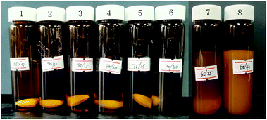
Since chloroform is a good solvent for PLA and ethanol is a nonsolvent, ethanol addition to the traditional spinning solution (PLA/chloroform) can make the spinning solution form a phase separation system and accelerate the formation of fibers in the electrospinning process. Meanwhile, the addition of ethanol will also reduce the solubility of PLA in the chloroform/ethanol mixed solution. When the amount of ethanol reaches a certain level, PLA cannot be completely dissolved. Three preparations for each spinning solutions to ensure the accuracy and repeatability of the dissolution of PLA in the mixed solvent. The results show that the experiment had good repeatability. The mixtures with different mass ratios of PLA/chloroform/ethanol after 24 h dissolving are shown in Fig. 1.It can be seen from Fig. 1 that, when the proportion of ethanol in the mixed solvent was less than 30 wt%, 10 wt% of PLA particles could be completely dissolved to obtain a transparent and uniform solution. When the proportion of ethanol was 35 wt%, the solution was supersaturated and contained some swelling particles, and there existed obvious stratification. When the proportion of ethanol increases to 40 wt%, the solubility of PLA particles was further reduced, the solute swelled into gel and a large number of insoluble PLA particles were observed.
For no. 1 to 6 solutions, electrospinning was carried out under the optimized electrospinning technologic parameters. Among them, the solvent of no. 5 and 6 spinning solutions (chloroform/ethanol = 75/25, 70/30 wt%) volatilized quickly in the electrospinning process. Under the action of voltage, after 30 s of rapid pushing and squeezing, the PLA fibers could be quickly fabricated from the spinneret before reaching the receiver and the PLA fibers collected on the aluminum foil were seldom bonded. The solvent volatilization speed of no. 4 solution (chloroform/ethanol = 80/20, wt%) was slower than those of no. 5 and 6 solutions in the electrospinning process. During the spinning process, some solvents could not be volatilized in time and followed the PLA to reach the collecting aluminum foil, therefore it was necessary to pause for 15 to 30 s and waited for the residual solvent to evaporate after rapid spinning 10 s. As for no. 3 solution (chloroform/ethanol = 85/15 wt%), due to the small proportion of ethanol, the solvent volatilized more slowly during the electrospinning process and a large amount of solvent had been seen on the collected aluminum foil after spinning for 5 s. More importantly, the droplets remained and could not be volatilized quickly in a short time, causing mutual adhesion or even redissolution of the fibers.
It could be seen that, as the proportion of ethanol in the mixed solvent decreased, the solvent volatilization and the fibers fabrication speeds gradually slowed down during the spinning process, which could not meet the requirements for rapid and large-scale preparation of PLA fibers. Therefore, no. 2 and 1 solutions (chloroform/ethanol = 90/10, 95/5 wt%) were excluded in the later research.
Morphology of rapid electrospinning fibers
The prepared fibers samples no. 3 to 6 had different diameter sizes through rapid pushing and squeezing because of the Taylor cone splits,17 and their morphology images are shown in Fig. 2 and 3.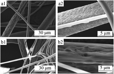 | ||
| Fig. 2 SEM micrographs of PLA fibers corresponding to the mass ratio of chloroform and ethanol of (a) 70/30 and (b) 75/25. | ||
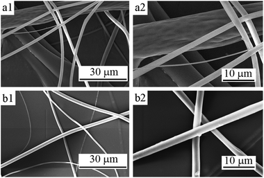 | ||
| Fig. 3 SEM micrographs of PLA fibers corresponding to the mass ratio of chloroform and ethanol of (a) 80/20 and (b) 85/15. | ||
Fig. 2 shows the SEM images of the 10 wt% PLA fibers corresponding to mass ratios of chloroform and ethanol of 70/30 and 75/25 (i.e., samples no. 6 and 5). It can be seen from Fig. 2 that the fiber diameters of sample no. 6 and sample no. 5 were different and the uniformity was poor. Among them, the diameters of sample no. 6 were mainly distributed in 3–20 μm (average diameter about 10.1 μm) and those of sample no. 5 were mainly distributed in 4–12 μm (average diameter about 7.1 μm). Because of the large amount of ethanol added in the spinning solution, the PLA solidification speed during the electrospinning process was so fast that there was a small amount of adhesion of the fibers. At the same time, the large amount of ethanol added made the phase separation obvious in the electrospinning process, the porous phenomenon of the fiber was clear. Moreover, unlike the spherical pores obtained by conventional electrospinning, the pores on fibers obtained from the PLA/chloroform/ethanol ternary system were slender groove-like, which indicated that the solution jet underwent a much stronger stretching force, as shown in Fig. 2(a2) and (b2).
Fig. 3 is the SEM images of the 10 wt% PLA fibers of no. 4 and 3 corresponding to mass ratios of chloroform and ethanol of 80/20 and 85/15. It can be clearly observed that, as the amount of ethanol added reduced, the diameter distribution of the obtained PLA fibers was more uniform. Sample no. 4 has a diameter ranging from 1.5 to 9 μm (average diameter about 5.6 μm), while the diameter of sample no. 3 was distributed from 3 to 6 μm (average diameter about 4.8 μm).
For the fiber surfaces, some fibers with larger diameters of no. 4 fibers had depressions and wrinkle-like surface, while the surface of no. 3 fibers was smooth, as shown in the Fig. 3(a2) and (b2). The decrease in ethanol content reduces the phase separation and porosity of the fiber was also significantly reduced.
Ethanol has a higher dielectric constant and conductivity and lower surface tension than those of chloroform (εethanol = 25.7, εchloroform = 4.9, σethanol = 1.35 × 10⁻¹⁰ S m−1, σchloroform < 1 × 10⁻¹⁰ S m−1, σethanol = 22.27 N m−1, σchloroform = 27.14 N m−1), so the addition of ethanol can reduce the surface tension of the spinning solution and balance the lower repulsion between charged elements, which is beneficial to forming uniformly stretched fibers. However, as a poor solvent for PLA, excessive addition of ethanol also causes uneven fiber stretching and make as-prepared fibers with uneven diameter distribution.18
It can be seen from Fig. 2 and 3 that the fibers no. 5 and 6 had obvious porous structure, while there appeared no porous structures on surfaces of no. 3 and 4 fibers. In the “polymer/solvent/nonsolvent” ternary system, the formation of porous fibers by electrospinning is related to the volatilization rate of solvent and nonsolvent. When the volatilization rate of solvent is greater than that of nonsolvent, the pore structure of fiber is obvious, while the volatilization rate of solvent and nonsolvent is equal, it is difficult to obtain porous fibers.14
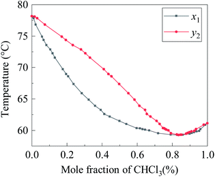
Chloroform volatilizes faster than ethanol at room temperature. According to Konovalov's law, two completely miscible liquids will form an azeotrope after mixing with a certain composition under a certain external pressure. Fig. 4 is the T–x1–y1 diagram of chloroform/ethanol binary system at 101.3 kPa and its vapor–liquid equilibrium data can be found in the literature.19 It can be seen that, under standard atmospheric pressure, when the ethanol content in the chloroform/ethanol mixed system is around 6.2 wt%, azeotropes will be formed. Therefore, in the “PLA/chloroform/ethanol” ternary system, the closer the mixing mass ratio of chloroform/ethanol is around to 93.8/6.2, the closer the volatilization rate of chloroform/ethanol is and the less obvious the pore structure of the PLA fiber obtained. This is the reason that the PLA fibers no. 6 owned the most obvious porous structures.
In conclusion, the addition of ethanol can accelerate the solidification and fabrication speed of the PLA fibers due to the nonsolvent induced phase separation. Meanwhile, the porosity of the fiber will be presented when ethanol content is no lower than 25% in the chloroform/ethanol mixture. Therefore, the PLA fibers of 10 wt% PLA spinning solution of chloroform 75/ethanol 25 could be prepared with rapid collection speed as well as porous structures.
Thermal properties of the electrospun fibers
The thermal properties of PLA fiber samples no. 3–6 and PLA resins were analyzed by DSC. The DSC thermograms of the various PLA samples and their thermal parameters are presented in Fig. 5 and Table 1, respectively.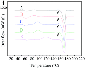 | ||
| Fig. 5 DSC curves of PLA fibers prepared from different chloroform/ethanol mixture solution. A: 70/30; B: 75/25; C: 80/20; D: 85/15; wt%, and E: PLA resin. | ||
| Sample no | Chloroform/ethanol (w/w) | Tg (°C) | Tcc (°C) | Tm (°C) | Cr (%) |
|---|---|---|---|---|---|
| 6 | 70/30 | 59.8 | 86.5 | 172.6 | 35.8 |
| 5 | 75/25 | 57.6 | 86.1 | 172.8 | 36.2 |
| 4 | 80/20 | 57.5 | 95.6 | 170.3 | 36.0 |
| 3 | 85/15 | 58.3 | 96.5 | 170.2 | 36.2 |
| PLA resin | — | 62.8 | 117.7 | 171.6 | 38.8 |
It can be seen from Fig. 5 and Table 1 that the Tm of samples no. 3 to 6 were basically the same as PLA resin, showing that both ESP-NIPS method and the ratio of chloroform/ethanol in the solvent have no significant effect on the melting temperature of the materials.
The Tg of the four kinds of PLA fibers obtained was between 57.5 °C and 60 °C, showing a slight decrease compared with PLA resin (Tg = 62.8 °C), which is a consequence of the rapid solidification and high elongation rate during electrospinning.20,21
The cold crystallization temperature Tcc of the sample fibers were significantly lower than the PLA resin and, with the increase of ethanol content, the decreasing degree of cold crystallization temperature increased. The main reason is that the spinning solution is extruded and stretched from the syringe during the electrospinning process, which limits the spatial size of the PLA crystallization to a certain extent, so the cold crystallization temperature and crystallinity of the PLA fibers are lower than PLA resin.22,23 Meanwhile, as the amount of ethanol increases, the degree of phase separation increases and the initial crystals in the polymer-rich region in the ternary system may play a role as a nucleating agent, which will also significantly reduce the cold crystallization temperature of PLA fibers.24
The crystallinity of the four fibers was about 36%, which was lower than the crystallinity of pure PLA resin (38.8%), indicating that different spinning solution compositions have no obvious effect on the crystallization of the polymer and the formation process of the ESP-NIPS reduces the crystallinity of the material. Studies have confirmed that the electrospinning hindered the crystallization process of polymers. This is because the polymer fibers solidify so rapidly and the crystallization process is interrupted by the electrospinning process that the electrospinning process cannot provide enough time for the crystallization of PLA, that is, there is not enough time for PLA to form a perfect crystal structure.24 At the same time, the formation of polymer crystals is also hindered by extremely high drafting of polymer chains during spinning. Therefore, the crystallinity of polymer electrospun fibers decrease due to the fast solidification speed and extremely high drafting rate of the fibers.25 In this study, the phase separation of nonsolvent, ethanol, also affected the crystallinity of PLA fibers to a certain extent, because the presence of nonsolvent accelerated the solidification of PLA solution. When the spinning solution is fiberized in the electrostatic field, the molecular chain of PLA cannot form a perfect crystal structure due to rapid solidification.
In addition, it can be seen from Fig. 5 that there is a small exothermic peak (indicated by the arrow in Fig. 5) before the melting peak (Tm) in the DSC curve of samples no. 3–6, while there is no such exothermic peak in the DSC curve of PLA resin, which may be caused by the decrease of cold crystallization temperature. Studies have shown that the exothermic peak will be observed by DSC curve of PLA when Tcc <110 °C and disappear when Tcc >110 °C due to the transformation of PLA crystal form.26,27 Therefore, there should be α′ crystals in the PLA fibers obtained from the ESP-NIPS preparation.
Crystallinity properties of the electrospun fibers
The crystal structure of PLA fiber membranes obtained from different spinning systems was analyzed by XRD. Fig. 6 shows XRD patterns of the PLA fibers prepared by electrospinning with different chloroform/ethanol mixed solvents. It can be found that all the PLA fibers prepared by ESP-NIPS exhibit sharp narrow peaks at 2θ angle of 16.7 and 19.1°, which correspond to {110}/{200} crystal plane and {203} crystal plane of α PLA, respectively. At 2θ angle of 22.5°, the weak diffraction peak also appears, which is the {015} plane of α crystal.26,28–31 In addition, it is observed in Fig. 6 that the diffraction peaks of crystal planes of the four fibers shifted slightly to the left with the decrease of ethanol content. In curve D (sample no. 3, chloroform/ethanol = 85/15 wt%), the diffraction peaks shifted the most at 18.7°, indicating the existence of α′ crystals in PLA fibers. Combined with DSC and XRD results, it can be concluded that the PLA fibers should contain both α crystals and α′ crystals in the transition state.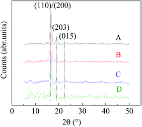 | ||
| Fig. 6 XRD patterns of PLA fibers prepared from different chloroform/ethanol mixture solution. A: 70/30; B: 75/25; C: 80/20; D: 85/15 wt%. | ||
Mechanism analysis of rapid formation of PLA fiber by ESP-NIPS
Electrospinning is a process of phase separation into fibers. For the good solvent electrospinning, the solution is ejected through the spinneret under the effect of electric field, stretched and split into small jets. The specific surface area of jets increases rapidly to volatilize the solvent and the polymer solidifies on the collecting plate, thereby a fiber membrane is prepared. However, for the ESP-NIPS spinning solution, the nonsolvent of the polymer increases the phase separation obviously in the electrospinning process. In order to explore the influence of the introduction of NIPS furtherly, a phase diagram of the “nonsolvent-solvent–polymer” ternary system is established through theoretical calculation and the PLA/ethanol equilibrium swelling experiment.Evaluation of “C2H5OH/CHCl3/PLA” ternary system interaction parameters
The Gibbs free energy (ΔGm) of “nonsolvent (1)–solvent (2)–polymer (3)” ternary mixing system can be expressed according to the Flory–Huggins theory as follow:
 | (4) |
The binary interaction parameter between nonsolvent (C2H5OH) and solvent (CHCl3), g12, can be calculated from the excess Gibbs free energy (GE) obtained from the gas–liquid equilibrium data.32 Since chloroform and ethanol are completely miscible, the excess free energy can be expressed by the Wilson model.
 | (5) |
 | (6) |
 | (7) |
| 1 | 2 | V1 (cm3 mol−10) | V2 (cm3 mol−1) | (λ12 − λ11) (J mol−1) | (λ21 − λ22) (J mol−1) | Λ12 | Λ21 |
|---|---|---|---|---|---|---|---|
| C2H5OH | CHCl3 | 58.32 | 80.77 | 4550 | −834.1 | 0.1152 | 1.9390 |
Since ethanol cannot dissolve PLA, the volume fraction has no effect on the nonsolvent (C2H5OH)/polymer (PLA) interaction parameter χ13, that is, χ13 has nothing to do with the solvent concentration in the system, being a fixed constant. In general, χ13 can be determined by the equilibrium swelling method.34
The solvent (CHCl3)/polymer (PLA) interaction parameter χ23 can be calculated by the solubility parameter (δ). There are many calculation methods32 and eqn (8) suggested by Hansen35 is used in this paper:
 | (8) |
| Name (no) | V (cm3 mol−1) | δd | δp | δh |
|---|---|---|---|---|
| CHCl3 (2) | 58.32 | 17.8 | 3.1 | 5.7 |
| PLA (3) | 2.44 × 10⁵ | 17.5 | 9.5 | 7.3 |
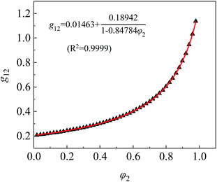
The interaction parameter of C2H5OH/CHCl3, g12, can be fitted and calculated from eqn (5) and (6). The fitting curve and results of g12 are shown in Fig. 7 and calculations of χ13 and χ23 are 1.8486 and 0.3575, respectively.
Ternary phase diagram and PLA forming mechanism
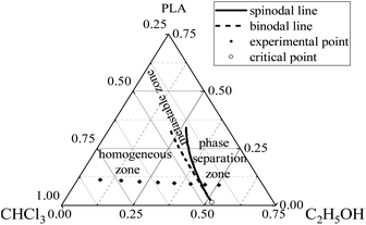
The binodal line, spinodal line and critical point of the ternary phase diagram can be computed from interaction parameters and the procedure relevant to the mathematical calculations was obtained from the literature.37 Therefore, the phase diagram of the “C2H5OH/CHCl3/PLA” ternary system was established, as shown in Fig. 8.In the phase diagram, the area outside the binodal line is the stable zone (i.e., the homogeneous zone), between the binodal line and the spinodal line is the metastable zone, and outside the spinodal line is the unstable zone (i.e., the phase separation zone). Combined with the phase diagram, it can be seen that, with the continuous addition of nonsolvent (ethanol) in the mixed solvent, the volume fractions of PLA and chloroform in the three-phase system decrease, the three-phase system gradually shifts from the homogeneous zone to the phase separation zone and the solutions change from clear and transparent to turbid and stratified, so PLA particles of no. 7 and 8 sample could not be completely dissolved and the stratification phenomenon occurred. At the same time, the closer the system composition is to the binodal line, the more easily the phase separation occurs. That is, from sample no. 3 to 6, the solidification effect of ethanol on the solute PLA is more and more obvious and the phase separation phenomenon during the electrospinning process is also more significant. Therefore, when the ethanol content in the mixed solvent reaches a certain level (20 wt%), the PLA fiber sprayed from the spinneret can be separated into fibers before reaching the aluminum foil receiver, forming a large amount of PLA nano-fiber mats in the air and achieving rapid fibers formation.
In the ESP-NIPS experiment, the composition of the original spinning solutions is in the homogeneous zone and no phase separation occurs, while the composition of the spinning solutions quickly transforms to the phase separation zone after electrospinning begins because of the volatilization of the solvent and nonsolvent.38 During the process of fiber solidification, since chloroform volatilizes faster than ethanol, the PLA solute solidifies into fibers and partial ethanol remains in the fibers and reach the receiver along with fibers when ethanol concentration in the mixed solvent is high enough (no less than 25 wt% in this study). When the PLA fibers furtherly dry and the ethanol completely evaporates, pores will be formed in the fibers.39 In contrast, pore structure of the fibers cannot be achieved when ethanol concentration in the mixed solvent is less than 20 wt% owing to its volatility.
Conclusions
In this paper, the rapid preparation of porous PLA fibers was achieved by combining the electrospinning with the nonsolvent induced phase separation and using chloroform as a good solvent and absolute ethanol as a nonsolvent. For the chloroform/ethanol mixed solvent, a clear and transparent PLA spinning solution was gained when the ethanol concentration is not more than 30 wt% and PLA fibers with porous structure would be prepared after electrospinning and NIPS. DSC and XRD results showed that the proportion of mixed solvents had different influence on Tcc, Tg and crystallinity of the PLA fibers, while had no obvious effect on Tm. When the ethanol content is about 25 wt%, rapid electrospinning was achieved, obtaining porous PLA fibers. The establishment of the ternary phase diagram model of the PLA/chloroform/ethanol system can be used to explain the formation mechanism of PLA porous fibers prepared by ESP-NIPS. The ternary phase diagram model can provide a theoretical basis for the formulation design of spinning solution as well. ESP-NIPS method is the effectual resolution for the rapid formation of polymer porous fibers.Author contributions
Bei Wang: methodology; formal analysis; investigation; writing-original draft, Junyan Yao: conceptualization; resources; writing-review & editing, Haoyu Wang: formal analysis; investigation, Mengqi Wang: investigation.Conflicts of interest
There are no conflicts to declare.Acknowledgements
This research did not receive any specific grant from funding agencies in the public, commercial or not-for-profit sectors.References
- I. Cacciotti, F. Pallotto, V. Scognamiglio, D. Moscone and F. Arduini, Mater. Sci. Eng., C, 2020, 111, 110744 CrossRef CAS PubMed.
- L. Fagiolari, E. Varaia, N. Mariotti, M. Bonomo, C. Barolo and F. Bella, Adv. Sustainable Syst., 2021, 5, 2100025 CrossRef.
- M. Beccatelli, M. Villani, F. Gentile, L. Bruno, D. Seletti, D. M. Nikolaidou, M. Culiolo, A. Zappettini and N. Coppedè, ACS Appl. Polym. Mater., 2021, 3, 1563–1572 CrossRef CAS.
- N. A. Rahman, S. A. Hanifah, N. N. Mobarak, A. Ahmad, N. A. Ludin, F. Bella and M. S. Su'ait, Polymer, 2021, 230, 124092 CrossRef CAS.
- J. Amici, C. Torchio, D. Versaci, D. Dessantis, A. Marchisio, F. Caldera, F. Bella, C. Francia and S. Bodoardo, Polymers, 2021, 13, 1625 CrossRef CAS PubMed.
- A. M. Al-Mohaimeed, G. A. E. Mostafa and M. F. El-Tohamy, Polymers, 2021, 13, 4459 CrossRef CAS PubMed.
- M. A. A. M. Abdah, M. Mokhtar, L. T. Khoon, K. Sopian, N. A. Dzulkurnain, A. Ahmad, Y. Sulaiman, F. Bella and M. S. Su'ait, Energy Rep., 2021, 7, 8677–8687 CrossRef.
- E. Rezabeigi, M. Sta, M. Swain, J. McDonald, N. R. Demarquette, R. A. L. Drew and P. M. Wood-Adams, J. Appl. Polym. Sci., 2017, 134, 44862 CrossRef.
- W. Ke, X. Li, M. Miao, B. Liu, X. Zhang and T. Liu, Coatings, 2021, 11, 790 CrossRef CAS.
- G. Fan, Y. Diao, B. Huang, H. Yang, X. Liu and J. Chen, J. Dispersion Sci. Technol., 2020, 41, 289–296 CrossRef CAS.
- M. Shahi, M. Nadari, M. Sahmani, E. Seyedjafari, N. Ahmadbeigi and A. Peymani, Cells Tissues Organs, 2018, 205, 9–19 CrossRef CAS PubMed.
- S. Liu, Y. Zheng, J. Hu, Z. Wu and H. Chen, New J. Chem., 2020, 44, 17382–17390 RSC.
- A. M. Afifi, H. Nakajima, H. Yamane, Y. Kimura and S. Nakano, Macromol. Mater. Eng., 2009, 294, 658–665 CrossRef CAS.
- K. A. G. Katsogiannis, G. T. Vladisavljevic and S. Georgiadou, Eur. Polym. J., 2015, 69, 284–295 CrossRef CAS.
- L. Wannatong, A. Sirivat and P. Supaphol, Polym. Int., 2004, 53, 1851–1859 CrossRef CAS.
- R. Casasola, N. L. Thomas, A. Trybala and S. Georgiadou, Polymer, 2014, 55, 4728–4737 CrossRef CAS.
- S. Shao, S. Zhou, L. Li, J. Li, C. Luo, J. Wang, X. Li and J. Weng, Biomaterials, 2011, 32, 2821–2833 CrossRef CAS PubMed.
- L. Natarajan, J. New, A. Dasari, S. Yu and M. A. Manan, RSC Adv., 2014, 4, 44082–44088 RSC.
- G. Chen, Q. Wang, Z. Ma, X. Yan and S. Han, J. Chem. Eng. Data, 1995, 40, 361–366 CrossRef CAS.
- S. Pirani, H. M. N. Abushammala and R. Hashaikeh, J. Appl. Polym. Sci., 2013, 130, 3345–3354 CrossRef CAS.
- F. Liu, R. Guo, M. Shen, S. Wang and X. Shi, Macromol. Mater. Eng., 2009, 294, 666–672 CrossRef CAS.
- S. Zou, R. Wang, B. Fan, J. Xu and Z. Fan, J. Appl. Polym. Sci., 2018, 135, 45980 CrossRef.
- H. Luo, Y. Huang, D. Wang and J. Shi, J. Polym. Sci., Part A: Polym. Chem., 2013, 51, 376–383 CrossRef CAS.
- E. Rezabeigi, P. M. Wood-Adams and N. R. Demarquette, Macromolecules, 2018, 51, 4094–4107 CrossRef CAS.
- J. M. Deitzel, J. D. Kleinmeyer, J. K. Hirvonen and N. C. B. Tan, Polymer, 2001, 42, 8163–8170 CrossRef CAS.
- J. Zhang, K. Tashiro, H. Tsuji and A. J. Domb, Macromolecules, 2008, 41, 1352–1357 CrossRef CAS.
- H. Zhou, T. B. Green and Y. L. Joo, Polymer, 2006, 47, 7497–7505 CrossRef CAS.
- J. M. Zhang, Y. X. Duan, H. Sato, H. Tsuji, I. Noda, S. Yan and Y. Ozaki, Macromolecules, 2005, 38, 8012–8021 CrossRef CAS.
- P. Pan, Z. Liang, B. Zhu, T. Dong and Y. Inoue, Macromolecules, 2009, 42, 3374–3380 CrossRef CAS.
- P. Pan, W. Kai, B. Zhu, T. Dong and Y. Inoue, Macromolecules, 2007, 40, 6898–6905 CrossRef CAS.
- H. Marubayashi, S. Akaishi, S. Akasaka, S. Asai and M. Sumita, Macromolecules, 2008, 41, 9192–9203 CrossRef CAS.
- Y. Wei, Z. Xu, X. Yang and H. Liu, Desalination, 2006, 192, 91–104 CrossRef CAS.
- R. Koningsveld and L. A. Kleintjens, Macromolecules, 1971, 4, 637–641 CrossRef CAS.
- J. Y. Lai, S. F. Lin, F. C. Lin and D. M. Wang, J. Polym. Sci., Part A: Polym. Chem., 1998, 36, 607–615 CrossRef CAS.
- C. M. Hansen and L. Just, Ind. Eng. Chem. Res., 2001, 40, 21–25 CrossRef CAS.
- S. Sato, D. Gondo, T. Wada, S. Kanehashi and K. Nagai, J. Appl. Polym. Sci., 2013, 129, 1607–1617 CrossRef CAS.
- M. Karimi, W. Albrecht, M. Heuchel, M. H. Kish, J. Frahn, T. Weigel, D. Hofmann, H. Modarress and A. Lendlein, J. Membr. Sci., 2005, 265, 1–12 CrossRef CAS.
- Z. Qi, H. Yu, Y. Chen and M. Zhu, Mater. Lett., 2009, 63, 415–418 CrossRef CAS.
- Z. Lu, B. Zhang, H. Gong and J. Li, Polymer, 2021, 226, 123797 CrossRef CAS.
| This journal is © The Royal Society of Chemistry 2022 |

