DOI:
10.1039/D1RA09406H
(Paper)
RSC Adv., 2022,
12, 5665-5676
Unveiling the charge transfer behavior within ZSM-5 and carbon nitride composites for enhanced photocatalytic degradation of methylene blue
Received
28th December 2021
, Accepted 4th February 2022
First published on 16th February 2022
Abstract
ZSM-5/graphitic carbon nitride (g-C3N4) composites were successfully prepared using a simple solvothermal method. By varying the amount of ZSM-5 and g-C3N4 in the composites, the charge carrier (electrons and holes) transfer within the materials, which contributes to the enhanced photocatalytic performance, was unraveled. The X-ray diffraction (XRD), Fourier-transform infrared (FTIR), and scanning electron microscopy (SEM) analysis revealed that more ZSM-5 component leads to a stronger interaction with g-C3N4. The photocatalytic performance test toward methylene blue (MB) degradation shows that more ZSM-5 in the composites is beneficial in enhancing photocatalytic activity. Meanwhile, the impedance electron spectroscopy (EIS) and photoluminescence (PL) analysis revealed that ZSM-5 facilitates the charge carrier transfer of photogenerated electrons and holes from g-C3N4 to the catalyst surface due to its lower charge transfer resistance. During the charge carrier migration, the interface between g-C3N4 and ZSM-5 particles may induce higher resistance for the charge carrier transfer, however after passing through the interface from g-C3N4 to ZSM-5 particles, the charge carrier can be efficiently transferred to the surface, hence suppressing the charge carrier recombination.
Introduction
Dye waste is considered as an environmental pollutant and has negative impacts on the environment and human health.1,2 Therefore, the removal of dye molecules from the water body becomes crucial. Several water-treatment processes have been employed for dye removals, such as filtration, adsorption, and chemical deposition.3–5 However, those processes cannot totally remove the dye molecules since they only encapsulate the dye molecules into certain materials, for example, in the adsorbents or the membranes. Hence, further treatments are still needed. In this regard, photocatalysis reaction has attracted considerable attention6,7 since the photocatalytic process is able to degrade the dye molecules into CO2, water, or other less harmful ions or molecules as the final products.8 Thus, further treatments are not needed, which is beneficial in terms of practicality and the economy.
Several semiconductors have been employed as photocatalyst materials for the photodegradation of organic pollutants. For example, WO3 was reported to be an efficient photocatalyst due to its tunable bandgap, unique band positions, and excellent electronic properties that promoted its stability and photoactivity.9 Generating heterojunction in WO3, such as in Bi2WO6/Fe2O3/WO3 S-scheme ternary system, will further enhance the performance toward bisphenol-A degradation due to the efficient charge carriers separation and its ability to maintain redox reaction.10 Another material such as Cu2−xSe microsheet was reported to be an efficient photocatalyst for rhodamine B degradation, showing a complete discoloration within 30 minutes due to the highly accessible active sites and wider light absorption ranges as a result of the narrower bandgap.11 In terms of rhodamine B degradation, recently MoS2/tourmaline composite was also reported to have enhanced performance due to the increased dispersion of MoS2 nanosheet on the tourmaline support, which exposed more active sites. Moreover, the strong electric field in the tourmaline surface suppressed the recombination of charge carriers.12
The aforementioned photocatalysts are based on metal catalysts. Nowadays, nonmetal photocatalysts were also obtained considerable attention due to their synthesis practicality and abundant source. Among nonmetal photocatalysts, graphitic carbon nitride (g-C3N4) has been considered as one of the promising materials for photocatalytic process13 because it has a narrow bandgap (∼2.7 eV), good chemical and thermal stability, nontoxicity, and relatively easy large-scale production with readily raw materials.14–16 Recently, g-C3N4 is also considered as an emerging material for biomedical applications, such as for biosensing, diagnosis, therapy, and antibacterial materials due to its good biocompatibility and unique fluorescence properties.17 However, pristine g-C3N4 still suffers from the rapid charge carriers (electrons and hole pairs) recombination. Hence, some modifications can be applied to suppress this limitation, such as by preparing porous g-C3N4 and g-C3N4-based composites. Porous g-C3N4 was reported to enhance photocatalytic activity due to the increased surface area and narrowed bandgap, which shortened the charge carriers transfer and improves the light absorption.18–20 Moreover, the preparation of g-C3N4-based composites can efficiently suppress the charge carriers recombination.21,22 Among supported materials, ZSM-5 is considered as an appropriate support for g-C3N4 due to its chemical, mechanical, and thermal stability, superior adsorption ability, large surface area, and unique pore structure. Furthermore, ZSM-5 has also been reported as suitable photocatalyst support due to its ability to delocalize the bandgap energy of the excited electrons and to decrease the recombination rate.23–25
Some researchers have utilized ZSM-5 as support material for g-C3N4. For example, Prakash et al. reported the use of ZSM-5/g-C3N4 as a photocatalyst for rhodamine-B and crystal violet degradation.25 Preparing ZSM-5/g-C3N4 consists of ZSM-5 and g-C3N4 with a mass ratio of 4![[thin space (1/6-em)]](https://www.rsc.org/images/entities/char_2009.gif) :1; it was observed that the ZSM-5 was decorated on the surface of g-C3N4 particles with strong interaction. Also, the charge recombination can be suppressed as indicated by the lower intensity in the photoluminescence (PL) spectra of ZSM-5/g-C3N4 compared to bare g-C3N4. The enhanced photocatalytic performance was attributed to the efficient separation of charge carriers and the formation of heterojunction between ZSM-5 and g-C3N4.25 Similar results were also reported by Pham et al. in ZSM-5 decorated O-doped g-C3N4.26 Despite the enhanced performance of ZSM-5 and g-C3N4 composites, the mechanism of charge carriers transfer within the composite's components and how the charge carrier recombination can be suppressed are still not well understood.
:1; it was observed that the ZSM-5 was decorated on the surface of g-C3N4 particles with strong interaction. Also, the charge recombination can be suppressed as indicated by the lower intensity in the photoluminescence (PL) spectra of ZSM-5/g-C3N4 compared to bare g-C3N4. The enhanced photocatalytic performance was attributed to the efficient separation of charge carriers and the formation of heterojunction between ZSM-5 and g-C3N4.25 Similar results were also reported by Pham et al. in ZSM-5 decorated O-doped g-C3N4.26 Despite the enhanced performance of ZSM-5 and g-C3N4 composites, the mechanism of charge carriers transfer within the composite's components and how the charge carrier recombination can be suppressed are still not well understood.
In this present study, we investigate the charge carrier transfer behavior within ZSM-5/g-C3N4 composites, which determines their photocatalytic performances. In this regard, three ZSM-5/g-C3N4 composites with significant differences of ZSM-5 and g-C3N4 composition were prepared to obtain noticeable differences of each composite. The photocatalytic test was performed toward methylene blue (MB) degradation as a reaction model. The study revealed that the photogenerated electrons and holes generated by g-C3N4 migrate to the catalyst surface facilitated by ZSM-5 particles due to their higher conductivity. The facilitated charge carriers transfer by ZSM-5 particles suppressed the charge carriers recombination, hence enhancing the catalytic performance of the ZSM-5/g-C3N4 composites compared to bare g-C3N4.
Experimental
Materials
The materials used in this work are melamine (C3N3(NH2)3, Sigma-Aldrich), citric acid monohydrate (C6H8O7·H2O, Merck, ACS grade), methylene blue (C16H18ClN3S, Merck), sodium hydroxide (NaOH, Merck), acetic acid (CH3COOH, Merck), ethylene glycol ((CH2OH)2, Merck), ZSM-5 (Pingxiang Naike Chemical), dimethyl sulfoxide (DMSO, (CH3)2SO, Sigma-Aldrich), methanol (CH3OH, SAP chemicals), isopropyl alcohol (IPA, (CH3)2CHOH, SAP chemicals) and L-ascorbic acid (C6H8O6, SAP chemicals) and deionized water.
Procedure
Synthesis of g-C3N4. g-C3N4 used in this works was porous g-C3N4. The synthesis of porous g-C3N4 was performed as reported by Kong et al., using citric acid as a pore-forming agent.19 In a typical procedure, 2.52 g (0.02 mol) melamine was poured into 40 mL deionized water, then was heated at 80 °C for 30 min under vigorous stirring. Meanwhile, 0.2 mmol citric acid was dissolved in 10 mL deionized water and was dropped into a melamine solution. The mixture was then continuously stirred for 2 h at 80 °C. The resulted suspension was then transferred into a 250 mL Teflon autoclave and was heated in an oven at 180 °C for 12 h. After heating, the powders were filtered and washed with deionized water. The precipitate was then dried at 80 °C for 2 h. The dried powder was calcined at 550 °C for 2 h.
Preparation of ZSM-5/g-C3N4 composites. Preparation of ZSM-5/g-C3N4 composites was carried out by solvothermal method using the same procedure as reported by Prakash et al.25 Before preparation, the commercial ZSM-5 was firstly modified using the desilication and dealumination processes. The desilication process was performed using NaOH. In brief, a certain amount of ZSM-5 was mixed with 0.25 M NaOH with the ratio between the mass of ZSM-5 to the volume of NaOH was 1:30. The mixture was then put into reflux equipment and was heated at 65 °C for 30 min. After reflux, the mixture was directly cooled down in an ice bath. The ZSM-5 powders were filtered and washed with water until reaching neutral pH. The powder was then dried in an oven at 105 °C for 3 h. The dried samples were then treated for the dealumination process with 0.01 M acetic acid with the same procedure as the desilication process. However, for the dealumination process, the ratio between the mass of ZSM-5 and the volume of acetic acid was set at 1:20. After the dealumination process, the resulting ZSM-5 powders were calcined at 550 °C for 6 h.2 ZSM-5/g-C3N4 composites were prepared as follows. 0.5 g of g-C3N4 was mixed with various amounts of ZSM-5 (0.0 g, 0.25 g, 0.5 g, and 1.0 g) in 25 mL of ethylene glycol. The mixture was then ultrasonicated for 2 h. The well-dispersed mixture was then transferred into Teflon autoclave and was heated at 120 °C for 8 h. After cooling, the resulting powders were filtered and were dried at 105 °C for 3 h. The resulting samples were then assigned as bare g-C3N4, GZ-1, GZ-2, GZ-3, respectively.
Material characterizations. Crystalline phase of the prepared samples was characterized by X-ray diffraction (XRD). The XRD analysis was performed using XRD PANalytical under Cu Kα irradiation (λ = 1.5406), with accelerating voltage and current of 40 kV and 30 mA. The analysis was carried out at a diffraction angle of 2θ (20–80°) with a scan-interval of 0.017°. The Fourier-transformed infra-red (FTIR) analysis was performed using Shimadzu IRAFFINITY-s using conventional KBr pellets. The surface morphology was observed using a scanning electron microscope (SEM) ZEISS EVO 10 with an accelerating voltage of 20 kV with a secondary electron (SE1) detector. The elemental composition and distribution were analyzed using energy dispersive X-ray (EDX APEX). The surface area was measured using Brunauer–Emmett–Teller (BET) N2 sorption Quantachrome NovaWin. The optical properties were characterized by UV diffuse reflectance spectroscopy (DRS) using Shimadzu UV2600-I, in which BaSO4 was used as the reference. The photoluminescence (PL) spectroscopy was performed using spectrofluorospectrophotometer Shimadzu RF-5301 with an excitation wavelength of 350 nm. The photoelectrochemical measurements and electrochemical impedance spectroscopy (EIS) were performed using the CHI 600E instrument. The samples were dropped cast on the surface of fluorinated-tin oxide (FTO) prior to measurement. The measurements were conducted in 0.5 M Na2SO4 under full-spectrum illumination. The EIS measurement was performed at −0.2 V vs. Ag/AgCl at a frequency of 0.1 to 105 Hz.
Photocatalytic test
Photocatalytic activity of samples was evaluated using MB degradation under UV-LED illumination (365 nm, 12 × 2 watt). Typically, 50 mg of the photocatalyst was added to 50 mL of a 20 ppm MB solution. Prior to the MB degradation test, the solution was allowed to stand for 1 hour under stirring in the dark to reach MB adsorption/desorption equilibrium. After 1 hour in the dark, the UV lamp was turned on. 2 mL of aliquot solution was taken periodically every 60 min up to 180 min. The concentration was determined using a UV-Vis spectrophotometer at a wavelength of 655 nm. The degradation rate constant was calculated based on the pseudo-first-order Langmuir–Hinshelwood equation as shown in eqn (1).| |
 | (1) |
where Ct is the concentration at time t min (ppm), C0 is the initial concentration (ppm), t is the reaction time (minutes), and k is the reaction rate constant.15
The detection of reactive species was performed by trapping experiment using different scavengers, namely DMSO, methanol, IPA, and L-ascorbic acid as scavengers for electrons (e−), holes (h+), hydroxyl radicals (˙OH), superoxide radicals (˙O2−), respectively. The experiments were similar to the photodegradation experiments with addition of the corresponding scavenger.15
Results and discussion
Material characterizations
The crystalline phase and the purity of the samples were characterized using XRD.27,28 As shown in Fig. 1, bare g-C3N4 exhibits pronounce peaks at 2θ of 13.2° and 27.5°. The peak 13.2° refers to the (100) crystal lattice of g-C3N4, which can be attributed to the in-plane repetitive unit of tri-s-triazine. The strongest peak at 27.5° corresponds to the (002) crystal plane, attributed to the interplanar stacking peak of the conjugated aromatic rings.29 Based on these XRD patterns, the g-C3N4 has been successfully formed with high purity and crystallinity. The XRD patterns of the ZSM-5 display the pronounce peaks at 2θ of 23.3°, 26.4°, 27.5°, and 30.1°, which correspond to the (533), (642), (733), and (555) reflection planes of ZSM-5, respectively. The XRD patterns of the GZ composites show mixed-phases between g-C3N4 and ZSM-5. As expected, the intensity of the g-C3N4 characteristic peak at 27.3° decreases from GZ-1 to GZ-3 along with the less portion of g-C3N4 in the composites.25
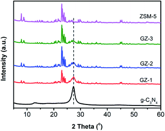 |
| | Fig. 1 XRD patterns of bare g-C3N4, ZSM-5, GZ-1, GZ-2, and GZ-3 catalysts. | |
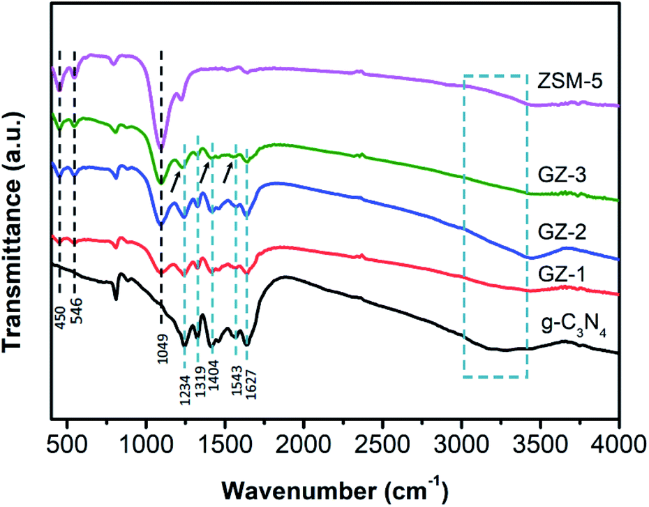
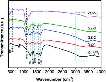
The FTIR analysis was then performed to further investigate the chemical composition of the GZ composite. As shown in FTIR spectra (Fig. 2), the GZ composites exhibit a mixed characteristic feature of g-C3N4 and ZSM-5 FTIR spectra. A broad peak around 3200 cm−1 can be assigned to the N–H bond stretching from amino groups (–NH2 or ![[double bond, length as m-dash]](https://www.rsc.org/images/entities/char_e001.gif) NH groups).30 The peaks at 1234, 1319, 1404, 1543, and 1627 cm−1 can be attributed to the vibration modes of the C–N stretching and CN stretching in the aromatic ring.31 The peak at 810 cm−1 corresponds to the out-of-plane skeletal bending modes of the tri-s-triazine ring.16,32 In the FTIR spectra of ZSM-5, the peak at 450 cm−1 refers to the buckling vibration of T–O–T, where T can be Si or Al atoms. The peak at 546 cm−1 can be observed, attributing to the formation of the pentasil ring by the tetrahedral SiO4 and AlO4 units.33 The symmetric stretching of the Si–O–Si group can be indicated by the peak at 789 cm−1. The peak at 1049 cm−1 and 1218 cm−1 can be attributed to the symmetric stretching of the Si–O–T group from the intra-tetrahedral mode of the zeolite framework.34 Moreover, the slight shifting in some peaks, especially at wavenumber of 1234 cm−1, 1404 cm−1, and 1543 cm−1, can also be observed in the GZ-3 samples, which indicates the strong chemical interaction between ZSM-5 and g-C3N4 particles in GZ-3.25,26 This result is in good agreement with the XRD results.
NH groups).30 The peaks at 1234, 1319, 1404, 1543, and 1627 cm−1 can be attributed to the vibration modes of the C–N stretching and CN stretching in the aromatic ring.31 The peak at 810 cm−1 corresponds to the out-of-plane skeletal bending modes of the tri-s-triazine ring.16,32 In the FTIR spectra of ZSM-5, the peak at 450 cm−1 refers to the buckling vibration of T–O–T, where T can be Si or Al atoms. The peak at 546 cm−1 can be observed, attributing to the formation of the pentasil ring by the tetrahedral SiO4 and AlO4 units.33 The symmetric stretching of the Si–O–Si group can be indicated by the peak at 789 cm−1. The peak at 1049 cm−1 and 1218 cm−1 can be attributed to the symmetric stretching of the Si–O–T group from the intra-tetrahedral mode of the zeolite framework.34 Moreover, the slight shifting in some peaks, especially at wavenumber of 1234 cm−1, 1404 cm−1, and 1543 cm−1, can also be observed in the GZ-3 samples, which indicates the strong chemical interaction between ZSM-5 and g-C3N4 particles in GZ-3.25,26 This result is in good agreement with the XRD results.
 |
| | Fig. 2 FTIR spectra of bare g-C3N4, ZSM-5, GZ-1, GZ-2, and GZ-3 catalysts. | |
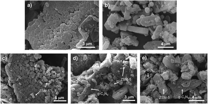
The surface morphology of the composites was then observed using SEM.35 As shown in Fig. 3, the bare g-C3N4 displays a wrinkled-interplanar structure with sheet-like morphology. The rough surface of the sheet particles indicates the formation of pores due to the utilization of acetic acid as a pore-forming agent during g-C3N4 synthesis.19 Meanwhile, the ZSM-5 shows a cubic-like or prism-like structure with some rough surface due to the desilication and dealumination process. The SEM images of the composite materials exhibit mixed particles between the g-C3N4 and ZSM-5 particles. In particular, the GZ-1 sample shows the dominance of g-C3N4 particles decorated with ZSM-5 particles on the surface. Unfortunately, it seems that the contact area between the ZSM-5 and of g-C3N4 is still limited. The GZ-2 shows more ZSM-5 particles together with g-C3N4 particles. As expected, the GZ-3 samples were dominated by the ZSM-5 particles. In this case, the g-C3N4 particles were surrounded by many ZSM-5 particles, creating more contact area and strong interaction between g-C3N4 and ZSM-5 particles. The more contact area between g-C3N4 and ZSM-5 particles are favorable in terms of the photogenerated charge carrier transport from g-C3N4 to the surface of the catalyst to further contact with the reactant.25
 |
| | Fig. 3 SEM images of (a) bare g-C3N4, (b) ZSM-5, (c) GZ-1, (d) GZ-2, and (e) GZ-3 catalysts. | |
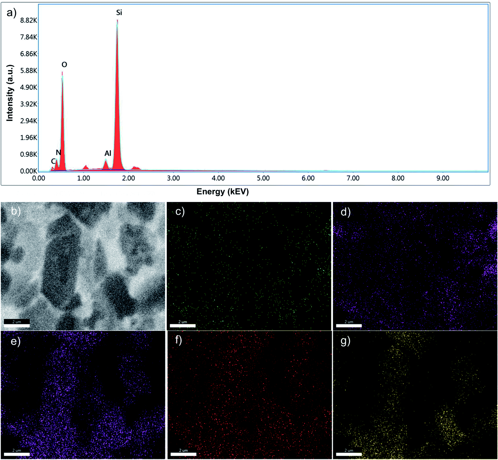
The elemental composition of GZ composites was also confirmed using EDX analysis (Fig. 4 and Table 1).36 As presented in Fig. 4a and Table 1, all GZ samples composed of major elements such as carbon (C) and nitrogen (N) as representative elements for g-C3N4 as well as silicon (Si), aluminium (Al), and oxygen (O) as representative elements for ZSM-5. The amount of C and N elements decrease from GZ-1 to GZ-3 as the proportion of g-C3N4 decreases (Table 1), which is in a good agreement with the SEM analysis. The elemental mapping of GZ-3 (Fig. 4b–g) show overlapping elemental distribution between elements from g-C3N4 and ZSM-5, which suggest a uniform distribution between the two components.
 |
| | Fig. 4 (a) EDX spectrum and (b) SEM micrograph with elemental mapping of (c) carbon (C), (d) nitrogen (N), (e) silicon (Si), (f) aluminium (Al), and (g) oxygen (O) of the GZ-3 composite. The scale bars represent 2 μm. | |
Table 1 Elemental composition of GZ composites
| Element |
GZ-1 |
GZ-2 |
GZ-3 |
| Weight (%) |
Atomic (%) |
Weight (%) |
Atomic (%) |
Weight (%) |
Atomic (%) |
| Carbon (C) |
15.28 |
20.22 |
8.02 |
11.91 |
3.92 |
6.10 |
| Nitrogen (N) |
28.33 |
32.15 |
13.66 |
17.40 |
9.91 |
13.21 |
| Silicon (Si) |
18.29 |
10.35 |
32.58 |
20.69 |
36.95 |
24.56 |
| Aluminium (Al) |
1.39 |
0.82 |
2.20 |
1.45 |
2.73 |
1.89 |
| Oxygen (O) |
36.71 |
36.46 |
43.54 |
48.54 |
46.48 |
54.24 |
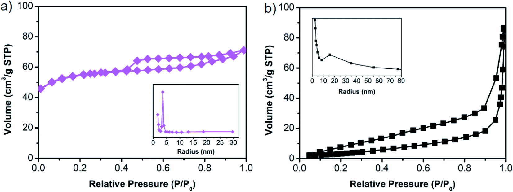
The surface area measurement was carried out using the N2 adsorption/desorption method on bare g-C3N4 and ZSM-5. As shown in Fig. 5, bare g-C3N4 and ZSM-5 show typical type IV isotherms with hysteresis loops according to the Brunauer–Deming–Teller classification. The specific surface area for g-C3N4 and ZSM-5 are 13.97 m2 g−1 and 281.97 m2 g−1, respectively. As typical type IV isotherms, both samples possess mesopores structure, with pore radii being distributed around ∼15.7 nm and ∼3.6 nm for g-C3N4 and ZSM-5, respectively. Based on the surface area measurement, the ZSM-5 may increase the specific surface area of the GZ composites, where the more ZSM-5 content in the GZ composites, the higher the surface area.25,26 In this regard, the higher specific surface area and the larger mesopores in g-C3N4 makes the GZ composites promising candidates for MB photodegradation with higher efficiency due to the facilitated mass transport and enhanced multilight scattering.37,38
 |
| | Fig. 5 N2 adsorption/desorption isotherms of (a) g-C3N4 and (b) ZSM-5. Inset is the corresponding pore size distribution. | |
Optical properties
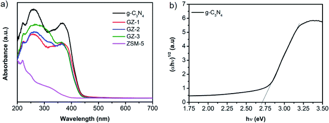
The optical properties of the GZ composites were firstly characterized by UV-vis diffuse reflectance spectroscopy (DRS). As shown in Fig. 6a, the DRS spectra of bare g-C3N4 and GZ composites exhibit two absorption peaks at 270 nm and 370 nm. The peak at 270 nm corresponds to the π–π* transition of CN groups in the conjugated aromatic triazine ring, while the peak at 370 nm can be attributed to the n–π* transition of C–N terminal in g-C3N4.39,40 All samples show strong absorption peaks both in UV and visible regions (400–450 nm). It is worth noting that the ZSM-5 also shows a slight absorption in the UV region. Moreover, the absorption edge of GZ composites exhibits a blue shift compared to the bare g-C3N4. Furthermore, the bandgap energy of g-C3N4 was then obtained from a plot of (αhν)1/2 versus hν as presented in the Tauc plots in Fig. 6b. A careful examination shows that the tailing edge of the g-C3N4 is 2.73 eV. The conduction band potential (ECB) and valence band potential (EVB) energies were calculated using the Mulliken electronegativity formula, as presented in eqn (2) and (3)where X is the electronegativity of material (g-C3N4, 4.73 eV) and E0 is the free electron energy (4.5 eV vs. NHE). Based on eqn (2) and (3), the ECB and EVB values of GZ-3 are −1.14 V and 1.60 V, which are similar to previous reports.15,25
 |
| | Fig. 6 (a) DRS spectra of bare g-C3N4, ZSM-5, GZ-1, GZ-2, and GZ-3 catalysts. (b) Tauc plot of bare g-C3N4. | |
Photocatalytic activity test
The photocatalytic activity of the photocatalyst materials was examined towards MB degradation. The main objective of this experiment is to find the MB photodegradation trend over various portions of ZSM-5 in bare g-C3N4 in GZ samples, hence it can indicate the determining component for photocatalytic activity and charge carrier behavior in the catalysts. At the first stage, we need to verify the component of the GZ, whether the g-C3N4 or ZSM-5, which has a dominant role in determining the performance. To achieve this objective, photodegradation experiments using the same amount of catalyst, i.e., 50 mg, were performed (detail in the experimental section).
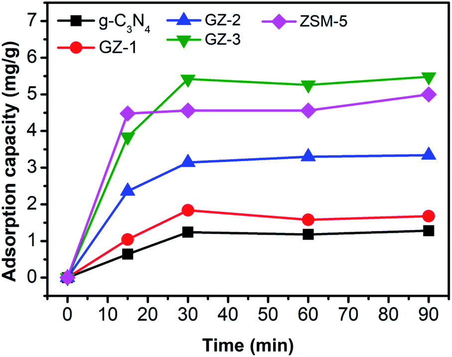
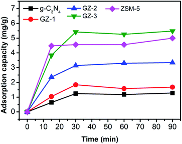
Prior to the photocatalytic degradation, the adsorption experiment using 50 mg samples was performed to reveal the adsorption capacity of the photocatalyst toward MB. In this regard, the adsorption capacity of the photocatalyst may differ due to the different proportions of g-C3N4 and ZSM-5. As presented in Fig. 7, the adsorption capacity of all samples increases rapidly within 30 min of adsorption time, followed by the relatively stable adsorption capacity up to 90 min. These results suggest that after 30 min, the adsorption process has reached equilibrium. The rapid adsorption process within 30 min was attributed to the presence of mesopores in the samples, which allows the diffusion of MB molecules into the pores.41 Moreover, the ZSM-5 seems to be the component, which determines the adsorption ability due to the porous nature. However, when high portion of ZSM-5 is combined with g-C3N4, as in GZ-3, the adsorption capacity was further enhanced, due to the combined effect between the porosity from ZSM-5 and the larger mesopores in g-C3N4. The lesser amount of ZSM-5 lead to the decrease on the adsorption capacity. Since the adsorption reached the equilibrium after 30 min, performing the stirring process for 1 h in dark before irradiating the reactor with UV light is sufficient to exclude the contribution of the adsorption process during the photocatalytic reaction. Hence, after 1 h of stirring in dark, the decrease of MB concentration under UV irradiation is contributed by the photocatalytic process.
 |
| | Fig. 7 Adsorption capacity of bare g-C3N4, ZSM-5, GZ-1, GZ-2, and GZ-3 catalysts. | |
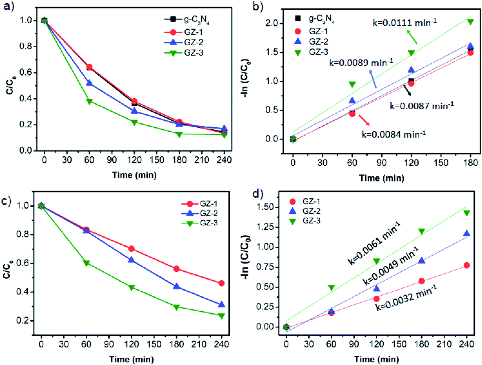
Without light irradiation, the photocatalyst is not able to degrade the MB as presented by the degradation curve of MB using bare g-C3N4 in the dark, as a primary photoactive material (Fig. 8a). Under UV light illumination, all materials are able to degrade the MB, in which the photodegradation trends of bare g-C3N4, GZ-1, GZ-2, and GZ-3 samples, are very comparable. Moreover, the degradation rates are also comparable, as indicated by the rate constant values (Fig. 8b and Table 2). Even though the degradation rate of all samples shows a similar trend and values, it does not mean that there is no enhancement in the photocatalytic activity upon the compositing of ZSM-5 and g-C3N4. In fact, it shows an indirect evidence of the enhancement and indicates the determining component which responsible for catalytic activity. Considering the composition of the catalysts, in 50 mg of GZ composites, the portion of g-C3N4 and ZSM-5 in each sample is different. As tabulated in Table 2, in 50 mg of tested catalysts, the amount of g-C3N4 are 50 mg, 33.3 mg, 25.0 mg, and 16.7 mg (or equal to 100%, 66.6%, 50.0%, and 33.3%) for each bare g-C3N4, GZ-1, GZ-2, and GZ-3, respectively. The remaining components are ZSM-5. Based on this component composition, we know that even with the lower amount of g-C3N4 in GZ-1, GZ-2, and GZ-3, the exhibited photocatalytic performances are still comparable with the pure g-C3N4. These results indirectly indicate the enhancement of photocatalytic activity since the photocatalytic activity is generally decreases along with the significantly lower photocatalyst dose.42 Please note that the degradation experiments were started after the adsorption process reached equilibrium (after 1 hour of adsorption in the dark), hence the contribution of the adsorption process can be excluded.
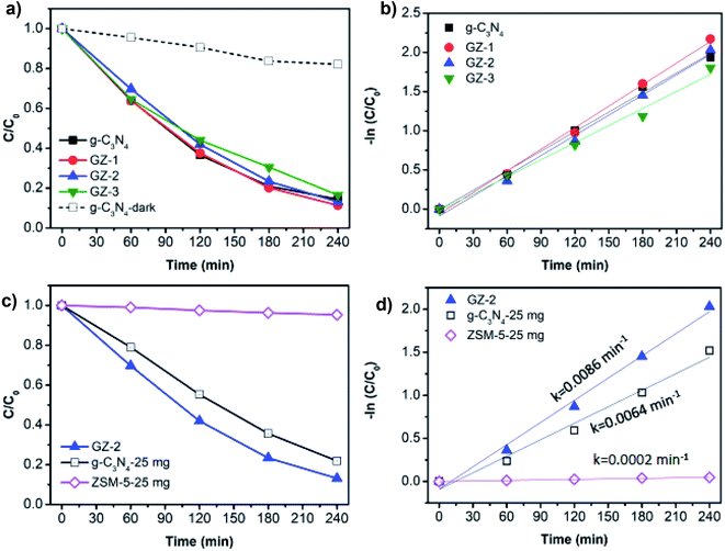 |
| | Fig. 8 (a) Photodegradation of MB over 50 mg g-C3N4, GZ-1, GZ-2, and GZ-3 catalysts and (b) corresponding Langmuir–Hinshelwood plots. (c) Photodegradation of MB over 50 mg of GZ-2 as a representative sample with the control experiments using the bare g-C3N4 and ZSM-5, and (d) corresponding Langmuir–Hinshelwood plots for the control experiments. | |
Table 2 The rate constants of various g-C3N4-based catalysts with their respective g-C3N4 and ZSM-5 composition
| Sample |
Rate constant (k, min−1) |
Component portion (%) |
| g-C3N4 |
ZSM-5 |
| g-C3N4 |
0.0083 |
100.0 |
0.0 |
| GZ-1 |
0.0092 |
66.7 |
33.3 |
| GZ-2 |
0.0086 |
50.0 |
50.0 |
| GZ-3 |
0.0073 |
33.3 |
66.7 |
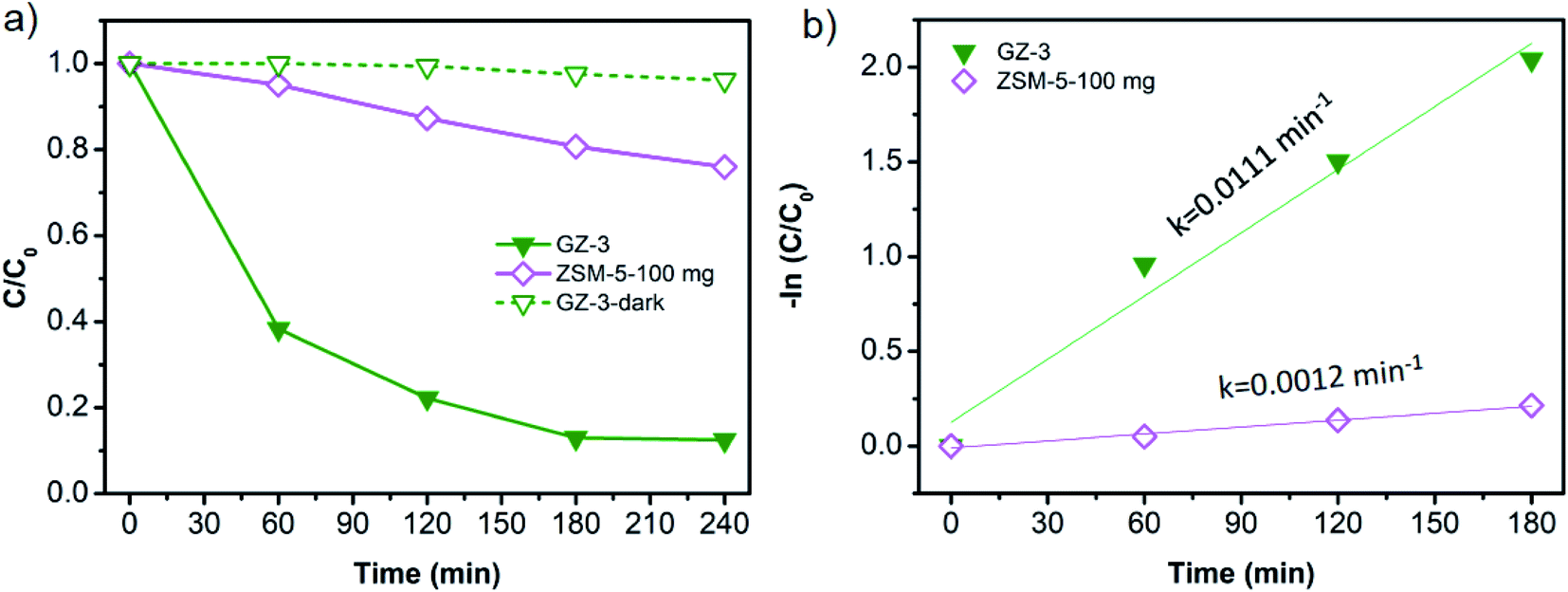
To further verify the contribution of ZSM-5 and the bare g-C3N4 in the GZ composites, we performed the MB photodegradation process using GZ-2 as representative GZ samples. 50 mg of GZ-2 consists of 25 mg of g-C3N4 and 25 mg of ZSM-5. Thus, performing the MB degradation experiment using 25 mg of g-C3N4 and 25 mg of ZSM-5 can give information on each component contribution and how much the contribution is. As presented in Fig. 8c and d, the 25 mg bare g-C3N4 exhibits a slower MB degradation rate compared to the GZ-2. Moreover, the MB degradation over 25 mg of ZSM-5 is negligible. These results verify that the determining component for the photocatalytic activity is the g-C3N4. It is reasonable considering the nature of g-C3N4, which can generate electrons and holes upon light irradiation. In the photocatalytic process, the photogenerated electrons and holes are two species that initiate the photodegradation process via direct or indirect degradation by forming radicals from water (˙OH and ˙O2−). In this regard, the ZSM-5 can serve as the support for g-C3N4, where the supporting mechanism will be discussed in the following sections.
Unveiling that the g-C3N4 is the determining component in GZ composites, we then performed the MB photodegradation using the same amount of g-C3N4 component for each sample. In this regard, the mass of total photocatalyst is 50 mg, 75 mg, 100 mg, and 150 mg for bare g-C3N4, GZ-1, GZ-2, and GZ-3, since all samples will have 50 mg of g-C3N4. In this case, the influence of the ZSM-5 amount in the GZ-composites can be investigated. The portion of ZSM-5 increases in the following order: GZ-3 > GZ-2 > GZ-1. The MB photodegradation plots of all samples are depicted in Fig. 9a. GZ-2 and GZ-3 show enhancement of the MB degradation rate compared to GZ-1 and bare g-C3N4. Surprisingly, the GZ-1 shows a comparable MB degradation with bare g-C3N4. Based on these results, the addition of more ZSM-5 into g-C3N4 is favorable for enhancing photocatalytic performance. The low amount of ZSM-5 as the support seems to have a small effect on the catalytic performance. Among the three GZ composites, the GZ-3 shows the highest MB degradation rate. The same trends are also observed and become more obvious using the higher initial concentration of MB (i.e. 40 ppm) as presented in Fig. 9c and d. To verify these results, the control experiments were conducted (Fig. 10a and b). The control experiment performed over 150 mg GZ-3 in the dark shows a negligible MB concentration decrease. Since the GZ-3 contains 100 mg of ZSM-5, the control experiment using 100 mg of ZSM-5 under light illumination was also performed and the result shows significantly slower MB concentration changes compared to the GZ-3. All of these results confirm that the MB degradation is mainly attributed to the activity of GZ-3, due to the synergistic effect between ZSM-5 and g-C3N4.
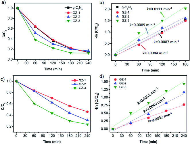 |
| | Fig. 9 (a) Photodegradation of MB over bare g-C3N4, GZ-1, GZ-2, and GZ-3 catalysts with a fixed amount of g-C3N4 as photoactive material in 20 ppm of MB, and (b) corresponding Langmuir–Hinshelwood plots. (c) Photodegradation of MB over bare g-C3N4, GZ-1, GZ-2, and GZ-3 catalysts with a fixed amount of g-C3N4 as photoactive material with a higher initial concentration of MB (40 ppm), and (d) corresponding Langmuir–Hinshelwood plots. | |
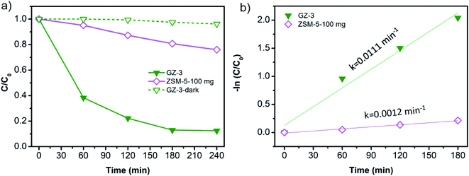 |
| | Fig. 10 (a) Photodegradation of MB and (b) corresponding Langmuir–Hinshelwood plots over 150 mg of GZ-3 with respective control experiments. The control experiments were performed in the dark and using 100 mg of ZSM-5 under UV illumination. The MB initial concentration is 20 ppm. | |
Apart from the synergistic effect between the g-C3N4 and ZSM-5 in GZ-3, the enhanced photocatalytic performance can also be attributed to the higher specific surface area of GZ-3 due to its higher ZSM-5 content. The higher specific surface area and the abundant mesopores in GZ-3 both originated from ZSM-5 and g-C3N4 enhance the multilight scattering. In this case, the large mesopores, especially in g-C3N4, induce a multiple-reflection effect on incident light, which facilitates the light transfer onto inner surface of GZ-3. As a result, the light absorption is improved.18,37,38 In addition to the enhanced multilight scattering, the large mesopores also facilitates fast mass transport.43–47
Mechanism of photocatalytic activity
The trapping experiments were performed to identify the reactive species, which are responsible for the MB photodegradation process. For this purpose, different scavengers such as DMSO, methanol, IPA, and L-ascorbic acid were added into GZ-3 as scavengers for electrons (e−), holes (h+), hydroxyl radicals (˙OH), ˙O2−, respectively. As shown in Fig. 11a, comparable degradation rates as in reaction without scavenger can still be observed by the addition of methanol and L-ascorbic acid, suggesting that the h+ and ˙O2− do not play a significant role in MB photodegradation. In contrast, the MB photodegradation rate significantly decreases with the addition of IPA into the reaction system and moderately decreases with the addition of DMSO. These results indicate that during the photocatalytic reaction ˙OH was produced and became the reactive species together with e− on the MB photodegradation process. This result is in good agreement with the previous report.25
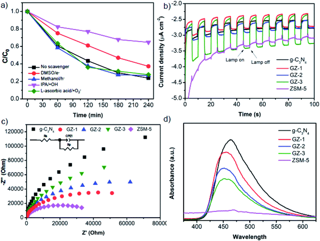 |
| | Fig. 11 (a) The reactive species trapping experiments for MB photodegradation over GZ-3 catalyst. Experiments were performed at MB initial concentration of 40 ppm. (b) Photocurrent spectra, (c) EIS Nyquist plots, and (d) PL spectra photocurrent spectra of bare g-C3N4, ZSM-5, GZ-1, GZ-2, and GZ-3 catalysts. | |
Based on the aforementioned results, the reaction mechanism can be predicted. When the GZ-3 composite was irradiated by UV light, the electrons (e−) are excited from valence band (VB) to conduction band (CB) with immediately generated h+ in the VB (eqn (4)). The h+ reacts with water to produce ˙OH (eqn (5)).25 The ˙OH and e− species finally involves in MB degradation as presented in eqn (6) and (7).
| | |
GZ-3 + UV irradiation → eCB− and hVB+
| (4) |
| | |
hVB+ + H2O → ˙OH + H+
| (5) |
| | |
˙OH + MB → mineralized products
| (6) |
| | |
eCB− + MB → mineralized products
| (7) |
Charge carriers behavior
The photocatalytic activity depends on the charge carriers (electrons and holes) transfer and recombination. Therefore, to investigate the charge carriers behavior, the photoelectrochemical measurements and steady-state PL analysis were performed. Fig. 11b exhibits the amperometric I–t curves of the samples coated on the surface of FTO glass in several on–off cycles. The exhibited photocurrent reflects the ability of the material to generate charge carriers under light illumination.48,49 All g-C3N4-based samples exhibit obvious photoresponse under full-spectrum illumination. Interestingly, ZSM-5 also shows slight photoresponse, which agrees with the UV-visible DRS spectra showing the absorbance in the UV region and rationalizes the slight MB degradation as presented in Fig. 10. While the bare g-C3N4, GZ-1, and GZ-2 show a comparable trend, the GZ-3 displays the highest photocurrent density, suggesting that the photoresponse ability of GZ-3 is improved and more charge carriers are generated and transferred.50,51
To further investigate the charge transfer and conductivity of the composites, the EIS analysis was performed. Fig. 11c shows the Nyquist plots of the composites samples with their fitted circuit. In general, the smaller semicircle in the high-frequency region indicates the smaller charge transfer resistance (RCT). In this regard, the Rs represents the series resistance, mainly from the solution impedance, while the RCT represents the charge transfer resistance within the material.28 As shown in Table 3, the Rs values are relatively comparable among the measured samples. Therefore, the resistance is dominantly affected by the RCT. It can be seen from Fig. 11c that all of the GZ composites generally have lower semicircles compared to the bare g-C3N4, suggesting the lower charge transfer resistance.52–54 It is worth noting that the ZSM-5 exhibits the smallest charge transfer resistance, which indicates the highest conductivity among the samples. Based on this observation, the presence of ZSM-5 in the GZ-composites can potentially facilitate the charge carrier transfer from g-C3N4. Possibly, the more conductive ZSM-5 facilitates the charge transfer from the bulk phase of g-C3N4 to the composite's surface.
Table 3 Rs and RCT values of over bare g-C3N4, ZSM-5, GZ-1, GZ-2, and GZ-3 catalysts
| Samples |
Rs (ohm) |
RCT (ohm) |
| g-C3N4 |
43.26 |
274250 |
| GZ-1 |
46.82 |
73906 |
| GZ-2 |
49.05 |
116170 |
| GZ-3 |
43.27 |
169560 |
| ZSM-5 |
52.63 |
40985 |
The PL spectra were then performed to investigate the separation and recombination of the photoinduced excitons. In general, a lower PL peak intensity reflects lower electron–hole pair recombination.55 As shown in Fig. 11d, the PL emission peaks of bare g-C3N4 was observed at 473 nm and exhibits the highest emission intensity, suggesting the rapid recombination of the electron–hole pairs. Upon combination with ZSM-5, the intensity of the PL emission peaks decreases and exhibits a blue shift, which agrees with the UV-vis DRS spectra.56 The decrease of the intensity is the following order: g-C3N4 > GZ-1 > GZ-2 > GZ-3. The more ZSM-5 portion in the composites, the lower the intensity. The results suggest that the presence of ZSM-5 in the g-C3N4-based composites reduces the recombination of electron–hole pairs, which agrees with the previous report.25 Considering a more inhibition of electron–hole pair recombination along with a more portion of ZSM-5 in the composites, it seems that more ZSM-5 in the GZ composites facilitates the electrons and hole transfer to the surface. Specifically, when the electrons and holes are generated in g-C3N4, the electrons and holes can be directly migrated to the ZSM-5, hence promoting the contact between the charge carriers (electrons and holes) with the reactant molecules. Note that ZSM-5 also has a porous structure, which provides more surface area. Because of this, the recombination can be suppressed by the presence of more ZSM-5 in the composites.
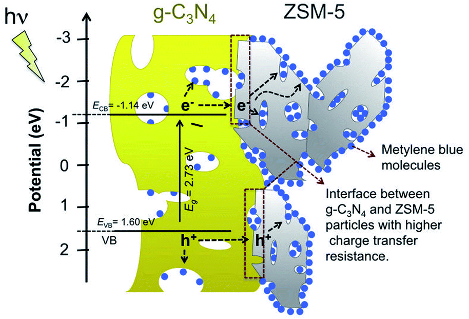
The results from PL analysis seem to have a different trend from the EIS results. However, it can be rationalized based on the charge transfer migration within the g-C3N4 and ZSM-5 particles. Based on EIS analysis, the more ZSM-5 portion in the composites, the higher charge transfer resistance. In this regard, the resistance in the composites may be mainly contributed by the interface resistance between the g-C3N4 and ZSM-5 particles. That is why the GZ-3 shows the highest charge transfer resistance since it has more contact area or interface between the ZSM-5 and g-C3N4 particles. When the charge carriers migrate from the bulk g-C3N4, they can be highly resisted in the interface between g-C3N4 and ZSM-5 particles. However, once the electrons or holes reach the ZSM-5 particles, the charges carrier can be migrated efficiently to the surface and makes contact with reactants (Fig. 12). Note that the ZSM-5 shows the lowest charge transfer resistance (Fig. 11c). In other words, in the GZ composites, the g-C3N4 serves as the main photoactive material, which generates the electrons and holes, while the ZSM-5 facilitates the transfer of photogenerated charge carriers to the surface and optimizes the contact with the reactant by providing a larger surface area. Moreover, because of the facilitated charge transfer migration in the ZSM-5 particles, either volume recombination or surface recombination of electron and hole pairs can be significantly suppressed. Therefore, although GZ-3 has the highest charge transfer resistance than GZ-1 and GZ-2, it shows the lowest charge carriers recombination due to the significantly suppressed charge carrier pairs recombination.
 |
| | Fig. 12 Schematic illustration of charge carriers transfer in ZSM-5/g-C3N4 composite. | |
Conclusions
In summary, the g-C3N4 was successfully composited with ZSM-5 to form ZSM-5/g-C3N4 composites with enhanced photocatalytic activity towards MB degradation. All samples exhibit well dispersion of g-C3N4 and ZSM-5 components with strong interaction as characterized by SEM, XRD, and FTIR analysis. The more portion of ZSM-5, as in GZ-3, leads to a stronger contact between the g-C3N4 and ZSM-5 particles. The UV-visible DRS analysis shows that bare g-C3N4 and GZ composites samples are responsive in the UV-visible region. The photocatalytic activity toward MB degradation confirms the photoactivity of bare g-C3N4 and GZ composites. More portion of ZSM-5 in the composites leads to better photocatalytic activity. The highest MB photodegradation activity was performed by GZ-3. The enhanced performance was attributed to the synergistic effect between g-C3N4 and ZSM-5, enhanced light scattering and the facilitated mass transfer. Unveiling the charge transfer behavior, the EIS and PL analysis reveal the enhanced charge carrier transfer from g-C3N4 to the surface of the catalyst facilitated by ZSM-5, which suppresses the charge carriers recombination. Additionally, the higher resistance may raise from the interface between g-C3N4 and ZSM-5 particles, suggesting that the strong and highly intact interaction between the g-C3N4 and ZSM-5 particles is an important factor to be considered in order to further facilitate the charge transfer in ZSM-5/g-C3N4 composites.
Conflicts of interest
There are no conflicts to declare.
Acknowledgements
The authors greatly acknowledge The Ministry of Education, Culture, Research, and Technology of Indonesia (Kementerian Pendidikan, Kebudayaan, Riset, dan Teknologi Republik Indonesia) for funding this work under the scheme of Penelitian Dasar 2021 with contract number 808/PKS/ITS/2021. We also highly acknowledge and appreciate Dr Yun Hau Ng of the City University of Hong Kong and his team for their help with optical characterizations and photoelectrochemichal measurements.
Notes and references
- L. Hu, C. Zhang, G. Zeng, G. Chen, J. Wan, Z. Guo, H. Wu, Z. Yu, Y. Zhou and J. Liu, RSC Adv., 2016, 6, 78595–78610 RSC
 .
. - A. Iryani, A. Masudi, A. I. Rozafia, D. Hartanto, M. Santoso, H. Nur and M. S. Azami, Inorganics, 2020, 8, 52 CrossRef CAS .
- R. Ediati, W. Aulia, B. A. Nikmatin, A. R. P. Hidayat, U. M. Fitriana, C. Muarifah, D. O. Sulistiono, F. Martak and D. Prasetyoko, Mater. Today Chem., 2021, 21, 100533 CrossRef CAS .
- M. Mouiya, A. Bouazizi, A. Abourriche, A. Benhammou, Y. El Hafiane, M. Ouammou, Y. Abouliatim, S. A. Younssi, A. Smith and H. Hannache, Mater. Chem. Phys., 2019, 227, 291–301 CrossRef CAS .
- J. O. Paul Nayagam and K. Prasanna, Chemosphere, 2022, 291, 132737 CrossRef CAS PubMed .
- F. Chen, T. Ma, T. Zhang, Y. Zhang and H. Huang, Adv, 2021, 33, 2005256 CAS .
- W. P. Utomo, M. K. H. Leung, Z. Yin, H. Wu and Y. H. Ng, Adv. Funct. Mater., 2022, 32, 2106713 CrossRef CAS .
- D. Ayodhya and G. Veerabhadram, Mater. Today Energy, 2018, 9, 83–113 CrossRef .
- P. Shandilya, S. Sambyal, R. Sharma, P. Mandyal and B. Fang, J. Hazard. Mater., 2022, 428, 128218 CrossRef CAS PubMed .
- P. Shandilya, A. Guleria and B. Fang, J. Environ. Chem. Eng., 2021, 9, 106461 CrossRef CAS .
- W. Zhong, S. Shen, S. Feng, Z. Lin, Z. Wang and B. Fang, CrystEngComm, 2018, 20, 7851–7856 RSC .
- M. Hao, H. Li, L. Cui, W. Liu, B. Fang, J. Liang, X. Xie, D. Wang and F. Wang, Environ. Chem. Lett., 2021, 19, 3573–3582 CrossRef CAS .
- G. Liao, C. Li, X. Li and B. Fang, Cell Rep. Phys. Sci., 2021, 2, 100355 CrossRef CAS .
- W.-J. Ong, L.-L. Tan, Y. H. Ng, S.-T. Yong and S.-P. Chai, Chem. Rev., 2016, 116, 7159–7329 CrossRef CAS PubMed .
- P. Lu, X. Hu, Y. Li, Y. Peng, M. Zhang, X. Jiang, Y. He, M. Fu, F. Dong and Z. Zhang, J. Saudi Chem. Soc., 2019, 23, 1109–1118 CrossRef CAS .
- S. Sun, X. Gou, S. Tao, J. Cui, J. Li, Q. Yang, S. Liang and Z. Yang, Mater. Chem. Front., 2019, 3, 597–605 RSC .
- G. Liao, F. He, Q. Li, L. Zhong, R. Zhao, H. Che, H. Gao and B. Fang, Prog. Mater. Sci., 2020, 112, 100666 CrossRef CAS .
- Y. Liu, S. Shen, Z. Li, D. Ma, G. Xu and B. Fang, Mater. Charact., 2021, 174, 111031 CrossRef CAS .
- L. Kong, J. Wang, X. Mu, R. Li, X. Li, X. Fan, P. Song, F. Ma and M. Sun, Mater. Today Energy, 2019, 13, 11–21 CrossRef .
- S. Wang, X. Han, Y. Zhang, N. Tian, T. Ma and H. Huang, Small Struct., 2021, 2, 2000061 CrossRef CAS .
- B. Fang, L. Daniel, A. Bonakdarpour, R. Govindarajan, J. Sharman and D. P. Wilkinson, Small, 2021, 17, 2102288 CrossRef CAS PubMed .
- Y. Liu, G. Xu, D. Ma, Z. Li, Z. Yan, A. Xu, W. Zhong and B. Fang, J. Cleaner Prod., 2021, 328, 129745 CrossRef CAS .
- Z. Shams-Ghahfarokhi and A. Nezamzadeh-Ejhieh, Mater. Sci. Semicond. Process., 2015, 39, 265–275 CrossRef CAS .
- G. R. Reddy, S. Balasubramanian and K. Chennakesavulu, RSC Adv., 2015, 5, 81013–81023 RSC .
- K. Prakash, S. Karuthapandian and S. Senthilkumar, Mater. Chem. Phys., 2019, 221, 34–46 CrossRef CAS .
- X. N. Pham, H. T. Nguyen, T. N. Pham, T.-T.-B. Nguyen, M. B. Nguyen, V. T.-T. Tran and H. V. Doan, J. Taiwan Inst. Chem. Eng., 2020, 114, 91–102 CrossRef CAS .
- D. Hartanto, R. M. Iqbal, W. E. Shahbihi, E. Santoso, H. Fansuri and A. Iryani, Mal. J. Fund. Appl. Sci., 2017, 13, 817–820 CrossRef .
- A. Aliyatulmuna, W. P. Utomo, H. Fansuri and I. K. Murwani, Asian J. Chem., 2017, 29, 2191–2196 CrossRef CAS .
- J. Li, Y. Wang, X. Li, Q. Gao and S. Zhang, J. Alloys Compd., 2021, 881, 160551 CrossRef CAS .
- Y. Jiang, Z. Lin, Y. Zhang, Y. Lai, D. Liang and C. Yang, New J. Chem., 2020, 44, 17891–17898 RSC .
- H. Li, Z. Liang, Q. Deng and W. Hou, J. Colloid Interface Sci., 2020, 564, 333–343 CrossRef CAS PubMed .
- S. K. Lakhera, R. T. Pangal, H. Y. Hafeez and B. Neppolian, ChemSusChem, 2019, 12, 4293–4303 CrossRef CAS PubMed .
- A. Iryani, M. M. Ilmi and D. Hartanto, Mal. J. Fund. Appl. Sci., 2017, 13, 832–839 CrossRef .
- W. Zhang, K. Wang, Y. Yu and H. He, Chem. Eng. J., 2010, 163, 62–67 CrossRef CAS .
- E. P. Setyaningsih, M. Machfudzoh, W. P. Utomo and H. Fansuri, Indones. J. Chem., 2018, 16, 20–24 CrossRef .
- H. Fansuri, I. M. Anisatun, A. Fatmawati, W. P. Utomo, W. Supriadi, R. Bayuaji and S. Subaer, Mater. Sci. Forum, 2016, 841, 186–192 Search PubMed .
- B. Fang, A. Bonakdarpour, K. Reilly, Y. Xing, F. Taghipour and D. P. Wilkinson, ACS Appl. Mater. Interfaces, 2014, 6, 15488–15498 CrossRef CAS PubMed .
- B. Fang, Y. Xing, A. Bonakdarpour, S. Zhang and D. P. Wilkinson, ACS Sustainable Chem. Eng., 2015, 3, 2381–2388 CrossRef CAS .
- S. M. Jasman, H. O. Lintang, S. L. Lee and L. Yuliati, Malaysian J. Anal. Sci., 2017, 21, 1316 Search PubMed .
- F. Hussin, H. O. Lintang, S. L. Lee and L. Yuliati, Mal. J. Fund. Appl. Sci., 2018, 14, 159–163 CrossRef .
- E. Santoso, R. Ediati, Y. Kusumawati, H. Bahruji, D. O. Sulistiono and D. Prasetyoko, Mater. Today Chem., 2020, 16, 100233 CrossRef CAS .
- A. Mohagheghian, S.-A. Karimi, J.-K. Yang and M. Shirzad-Siboni, J. Adv. Oxid. Technol., 2015, 18, 61–68 CAS .
- B. Fang, B. A. Pinaud and D. P. Wilkinson, Electrocatalysis, 2016, 7, 336–344 CrossRef CAS .
- F. Wang, Z. Xie, J. Liang, B. Fang, Y. Piao, M. Hao and Z. Wang, Environ. Sci. Technol., 2019, 53, 6989–6996 CrossRef CAS PubMed .
- F. Wang, P. Gao, J. Liang, T. Zhang, H. Zhang, Y. Ding, T. Xu and B. Fang, Ceram. Int., 2019, 45, 24923–24926 CrossRef CAS .
- Y. Xing, B. Fang, A. Bonakdarpour, S. Zhang and D. P. Wilkinson, Int. J. Hydrogen Energy, 2014, 39, 7859–7867 CrossRef CAS .
- Y. Zhang, X. Wang, F. Luo, Y. Tan, L. Zeng, B. Fang and A. Liu, Appl. Catal., B, 2019, 256, 117852 CrossRef CAS .
- G. Zhao, G. Liu, H. Pang, H. Liu, H. Zhang, K. Chang, X. Meng, X. Wang and J. Ye, Small, 2016, 12, 6160–6166 CrossRef CAS PubMed .
- L. Liu, H. Huang, Z. Chen, H. Yu, K. Wang, J. Huang, H. Yu and Y. Zhang, Angew. Chem., Int. Ed., 2021, 60, 18303–18308 CrossRef CAS PubMed .
- R. Zhao, X. Sun, Y. Jin, J. Han, L. Wang and F. Liu, J. Mater. Sci., 2019, 54, 5445–5456 CrossRef CAS .
- F. Chen, Z. Ma, L. Ye, T. Ma, T. Zhang, Y. Zhang and H. Huang, Adv. Mater., 2020, 32, 1908350 CrossRef CAS PubMed .
- K. Ao, Q. Wei and W. A. Daoud, ACS Appl. Mater. Interfaces, 2020, 12, 33595–33602 CrossRef CAS PubMed .
- J. Cheng, X. Yan, Q. Mo, B. Liu, J. Wang, X. Yang and L. Li, Ceram. Int., 2017, 43, 301–307 CrossRef CAS .
- Y. Zhang, J. Hu, C. Zhang, Y. Liu, M. Xu, Y. Xue, L. Liu and M. K. H. Leung, J. Mater. Chem. A, 2020, 8, 9091–9098 RSC .
- Z. Yong, J. Ren, H. Hu, P. Li, S. Ouyang, H. Xu and D. Wang, J. Nanomater., 2015, 2015, e821986 Search PubMed .
- O. Elbanna, M. Fujitsuka and T. Majima, ACS Appl. Mater. Interfaces, 2017, 9, 34844–34854 CrossRef CAS PubMed .
|
| This journal is © The Royal Society of Chemistry 2022 |
Click here to see how this site uses Cookies. View our privacy policy here. 
 Open Access Article
 This Open Access Article is licensed under a Creative Commons Attribution-Non Commercial 3.0 Unported Licence
 *a,
Grace Yuhanekaab,
Wahyu Prasetyo Utomo
*a,
Grace Yuhanekaab,
Wahyu Prasetyo Utomo