 Open Access Article
Magnetic field responsive microspheres with tunable structural colors by controlled assembly of nanoparticles†
Shenglong Shang *ab,
Kaiqi Zhanga,
Huifang Hua,
Xiaoran Sunc,
Jie Liua,
Yanpeng Nia and
Ping Zhua
aInstitute of Functional Textiles and Advanced Materials, College of Textiles & Clothing, State Key Laboratory of Bio-Fibers and Eco-Textiles, Qingdao University, Qingdao 266071, China. E-mail: shangsl@qdu.edu.cn
bState Key Laboratory for Modification of Chemical Fibers and Polymer Materials, College of Materials Science and Engineering, Donghua University, Shanghai 201620, China
cChinesisch-Deutsche Fakultät für Ingenieurwissenschaft, Qingdao University of Science & Technology, Qingdao 266599, China
First published on 16th February 2022
Abstract
Dynamic color tuning has many useful applications in nature for communication, camouflage, mood indication, etc. Structural colors have more advanced applications due to their ability to respond to external stimuli by dynamically changing color. In this work, we proposed an efficient method to prepare magneto-chromatic microspheres with tunable structural color. Through a microfluidic technique, the magneto-chromatic microspheres containing Fe3O4@C magnetic particles were continuously prepared. The size of the microspheres decreases with the increase of PVA solution phase to ETPTA phase flow rate ratio. Furthermore, the microspheres with larger sizes more easily form close packed structures. Microspheres can be constrained in PVA to form a free-standing film after the evaporation of water in PVA solution. The PVA film could display tunable brilliant structural colors when an external magnetic field is applied. Moreover, microspheres with fixed structural colors can also be acquired by polymerizing microspheres under UV light under an external magnetic field.
1. Introduction
Structural colors generated from the diffraction of light by colloidal photonic crystals have attracted great interest due to their durable, anti-photobleaching and bright colors.1,2 Colloidal photonic crystals usually form ordered lattices and create photonic stop bands for the control of light diffraction; brilliant color could be observed when the stopband falls into the visible region.3 Creating a photonic stop band through the crystallization of colloid particles in microspheres that generate microspheres with structural colors has great potential application in visualized biochemical sensors4–6 and color display devices.7–9 Particularly, microspheres with structural colors are usually fabricated by emulsion droplets.10,11 The colloidal particles dispersed in emulsion droplets formed closed packed arrangement as the solvent evaporated. Using this method, only microspheres with stationary color were obtained. Therefore, in order to acquire multi structural colored microspheres, colloidal particles with different sizes or mixed precursors at different concentrations were used to cover this requirement.12 However, microspheres that can't dynamically change their colors according to external stimuli are still limited.The chromatic transitions in response to external stimuli are very useful in nature and some creatures usually use these chromatic transitions for communication, camouflage, mood indication, etc13,14. Nature creatures such as chameleon, squid and cuttlefish have attracted much attention because they are dynamically changing their skin color according to the surrounding environments. It is well known that these creatures changed their body's color arising from the translocation of pigments or a rearrangement of reflective units within a number of chromatophores. Some studies also found that chameleons tuned their skin's color not only depending on the tuning of chromatophores in their skin, but also through active tuning of a lattice of guanine nanocrystals within a superficial thick layer of dermal iridophores.15 To achieve smart color changing artificially, a number of researches have focused on responsive photonic crystals.16 Responsive photonic crystals are dielectrically periodical structures that can alter their diffraction wavelength or intensities upon exposure to physical or chemical stimuli.17–26 The responsiveness of these materials relies on the corporation of periodical photonic crystal structures and the responsive materials. In other words, the color changing of responsive photonic crystals depends on the influence of responsive materials on periodical photonic crystals. Therefore, problems such as slow response to external stimuli, incomplete reversibility, and difficulty of integration into existing photonic devices have limited the application of responsive photonic crystal materials.16
To achieve fast structure tuning of responsive photonic crystal materials, magnetically responsive photonic crystals have been widely researched in recent years. For example, Bibette reported the ferrofluid droplets that displayed structural colors under an external magnetic field in 1993,27 Asher and his co-workers fabricated monodispersed magnetic polystyrene (PSt) composite spheres by emulsion polymerization in 2001.28 Magnetic particles with core–shell structures could be easily achieved through simple physical methods.29,30 For example, Tymoczko et al. produced colloidal Fe–Au core–shell nanoparticles in one step and with a yield approaching 99.7% in mass through a laser assisted synthetic method.29 So far, magnetic particles such as poly(acrylic acid) (PAA)-capped magnetite (Fe3O4) particles, silica encapsulated Fe3O4 (Fe3O4@SiO2), carbon encapsulated Fe3O4 (Fe3O4@C), poly(vinyl pyrrolidone) (PVP)-capped Fe3O4 (Fe3O4@PVP) and poly(methyl methacrylate-co-methacrylic acid) encapsulated Fe3O4 (Fe3O4@P(MMA-co-MAA)) particles have been widely studied.31–37 These magnetic particles can rapidly form one-dimensional chain like structures and display multi-structural colors in the presence of an external magnetic field, and the structural color usually depends on the size of magnetic particles and the external magnetic field.
Herein, an efficient strategy was used for the preparation of magneto-chromatic microspheres with tunable structural color. The magneto-chromatic microspheres which are composed of Fe3O4@C magnetic particle and ethoxylated trimethylolpropane triacrylate (ETPTA) were prepared by a microfluidic technique. It was found that the size of microspheres could be tuned by the flow rates and microspheres with larger sizes are more easily to form close packed structures. The microspheres were dispersed in PVA solution and after the PVA solution was dried, the microsphere can be constrained in the PVA film and display brilliant structural color according to an external magnetic field which could be used to mimic some smart color changing nature creatures. More importantly, microspheres with fixed structural colors can also be acquired by polymerizing microspheres under UV light and an external magnetic field. The microspheres may find some utilities in structural color displays as well as forgery protection and mimic smart color changing creatures in nature.
2. Experimental
2.1 Materials and chemicals
Ferrocene (Fe(C5H5)2, ≧98%), (ethoxylated trimethylolpropane triacrylate) (ETPTA), hydrogen peroxide (H2O2, ≧30%), acetone (C3H6O, ≧99%), and poly (vinyl alcohol) (PVA) were purchased from sigma-aldrich. Capillaries with different diameters were purchased from VitroCom Inc.2.2 Synthesis of Fe3O4@C particles
For the synthesis of Fe3O4@C particles, 0.50 g of ferrocene was dissolved in acetone (60 ml) under an intense sonication of 30 min to form a homogeneous solution, followed by the addition of hydrogen peroxide (2.0 ml) and stirred for 30 min under magnetic stirring. The obtained precursor solution was then sealed in a Teflon-lined stainless autoclave and heated at 190 °C for 72 h. After reaction, the autoclave was cooled naturally to room temperature. The products were isolated by a magnet and washed by acetone at least three times. Finally, the dark precipitates were re-dispersed in ETPTA as a concentration of 20 mg ml−1.2.3 Construction of microfluidic device
A capillary microfluidic device is designed to have one tapered cylindrical capillary assembled in another cylindrical capillary with a bigger diameter. The inner cylindrical capillary is tapered by puller (P-2000, Sutter Instrument) and then carefully sanded to have 200 μm orifice. Afterward, the capillary is merged into 2-[methoxy(polyethyleneoxy)propyl] trimethoxy silane (Gelest, Inc.) for 30 min in order to make it hydrophilic, then the capillary is dried by blowing air. Finally, one tip of the bigger capillary and the junction of two capillaries are sealed into two needles (the needles were firstly cut out appropriate holes by blade so that capillaries can stuck in it) by glue.2.4 Preparation of microspheres
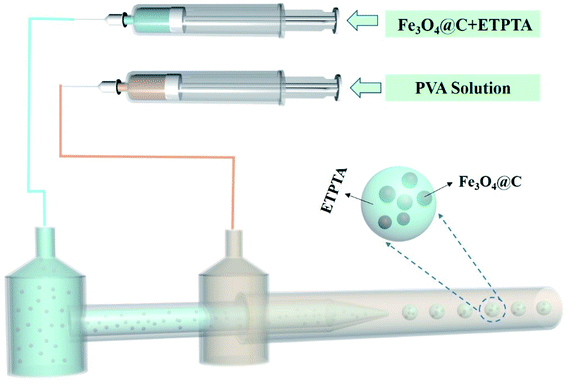
The microspheres were fabricated from microfluidic device, as shown in Fig. 1. Typically, ETPTA suspensions which containing Fe3O4@C magnetic particles was used as oil phase while PVA solution (10 w/w%) was used as continuous phase. The flow rate of PVA phase was controlled as 2000 μL h−1 and the flow rates of ETPTA phase were changing from 300 μL h−1 to 30 μL h−1. To get PVA films which constrained microspheres in it, the microspheres and PVA solution were put in the room temperature for 6 hours and PVA solution will dry automatically. For microspheres with fixed colors, PVA films were transformed into a magnetic field and polymerized under UV light for 30 seconds. Then the whole film was put into water and PVA will dissolve in water, after PVA completely dissolved in water, the polymerized microspheres were separated from the solution.2.5 Characterization
The microcapsules are observed with optical microscopy (BX 61, Olympus) in transmission modes. Digital photos of samples were obtained by a digital camera (Nikon D7000, Japan). The scanning electron microscopy (SEM) photographs were taken on a FEI Quanta Field Emission Gun Environmental SEM at an acceleration voltage of 5 kV. Transmission electron microscopy (TEM) images were obtained on FEI TF 20 at an acceleration voltage of 200 kV. The reflectance spectra were carried out on a USB4000 fiber optical spectrometer (Ocean Optics).3. Results and discussion
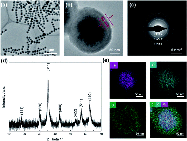
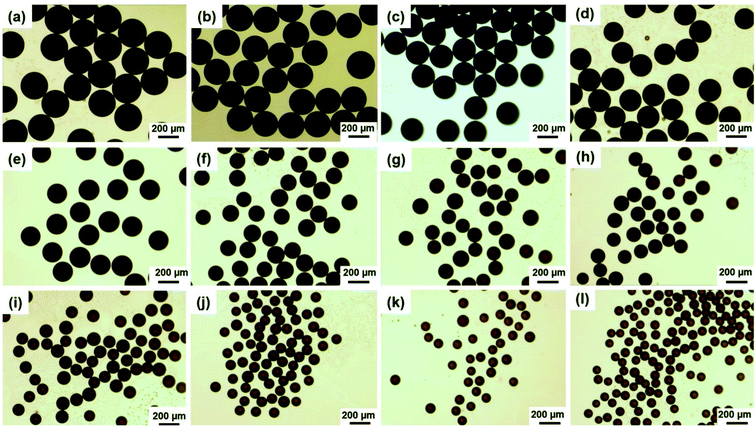
To fabricate magneto-chromatic microspheres that display tunable structural colors under the magnetic field, the Fe3O4@C particles were used and dispersed in ETPTA solution to form a homogenous suspension.38 The SEM image of magnetic Fe3O4@C particles were shown in Fig. S1.† Fe3O4@C particles are monodispersed and the diameters of these Fe3O4@C particles are about 203 nm. Fig. 1(a) demonstrates TEM images of Fe3O4@C particles, which illustrated that Fe3O4@C has core–shell structure in shape. The shell structure has a thickness of 33 nm by measuring the TEM photograph. The distribution of Fe, O and C also illustrated the core–shell structure of the particle in Fig. 1(e). A typical SAED pattern of a single Fe3O4@C is shown in Fig. 1(c), it can be observed that a clear sharp diffraction rings, which indicated the polycrystalline nature of the products. Its arcs and rings indexed as (111), (220), and (311) reflections for magnetite, respectively.39 Fig. 1(g) illustrates a typical XRD patterns of Fe3O4@C particles. As shown in the XRD patterns, iron oxides (JCPDS file 19-0629, magnetite, or JCPDS file 39-1346, maghemite) peaks can be clearly observed. The grain size of Fe3O4@C is 9.21 nm by calculating with the Debye–Scherrer formula for the strongest peak (311) gave.With the help of the microfluidic technology, the properties of microspheres such as controllable size and good sphericity can be easily achieved.36,40 During the fabrication of magneto-chromatic microspheres, the PVA (10 w/w%) solution was used as the continuous phase, and ETPTA suspension which contains Fe3O4@C nanoparticles was used as oil phase, the structure of microfluidic device was shown in Fig. 2. In order to make magnetic field response microspheres with different sizes, the flow rates of oil phases were tuned. During the fabrication process, the continuous phase flow rate was fixed at 2000 μL h−1, while the oil phase flow rates were controlled as 300, 250, 200, 150, 100, 90, 80, 70, 60, 50, 40, 30 μL h−1 respectively. Fig. 3 shows optical macroscope images of the microspheres fabricated at different oil phase flow rates, it can be clearly observed that with the decrease of the oil phase flow rates, the sizes of the microspheres decreased gradually.
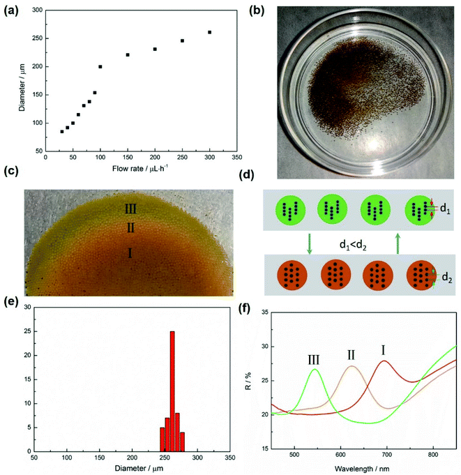
To understand the influence of flow rates to the microspheres sizes, size distributions of the spheres fabricated at different flow rates were measured by calculating about 50 microspheres. Fig. S2† demonstrates the size distributions of each microsphere fabricated at different flow rates. The average diameters of these microspheres fabricated at the flow rates of 300, 250, 200, 150, 100, 90, 80, 70, 60, 50, 40, 30 μL h−1 are about 261, 246, 231, 221, 200, 154, 138, 131, 115, 100, 92, 85 μm respectively. The results demonstrated that the size of microspheres gradually decreased when the flow rates changed from 300 to 100 μL h−1. While there is a sharp decrease when the flow rates changed from 100 to 30 μL h−1, that means if the flow rates are reduced to a certain extent, the sizes of microspheres are more sensitive to flow rates, as shown in Fig. 3(a). Furthermore, the microspheres are more likely to form close-packed structures when they have bigger sizes, as shown in Fig. S3,† the two samples were collected by a glass slides, from the optical microscope images of microspheres with two different diameters, 231 μm (a) and 100 μm (b), the microspheres with the diameter of 231 μm formed close packed structures while microspheres with diameter of 100 μm only randomly dispersed in PVA solution.
The microspheres are randomly dispersed in the PVA solution after being collected by a Petri dish (Fig. 4b). The original color of these microspheres is brown which results from the color of the Fe3O4@C particles.34 The microspheres showed a uniform size distribution and the average diameter of these microspheres are about 260 μm (see Fig. 4e). When an external magnet was put under the Petri dish, these microspheres gradually gathered together and immediately changed their color, as shown in Fig. 4(c). It is worth mentioning that the optical properties of microspheres were only dependent on the size of Fe3O4@C particles inside, and the size of microspheres would not affect their colors under an external magnetic field. The reason of microspheres displayed colors under magnetic field derived the assembly of Fe3O4@C particles.41 Fe3O4@C particles were randomly dispersed in ETPTA because of the electrostatic repulsion. However, an external magnetic field would break the balance and drive the Fe3O4@C particles to form an ordered structures. The color of suspension depends on the center–center distance of each adjacent particle,42 and the following equation can explain the color changing of the suspension:41
F2 = ▽(m × H1) = 3(1 − 3![[thin space (1/6-em)]](https://www.rsc.org/images/entities/char_2009.gif) cos2 cos2![[thin space (1/6-em)]](https://www.rsc.org/images/entities/char_2009.gif) α)m2/d4 × r α)m2/d4 × r
| (1) |
The microspheres displayed different colors at part I, II and III. That's mainly because of magnetic field of the magnet is not uniform, the magnetic field intensity at the edge is stronger than it in the center, induced the distance between each adjacent magnetic particle in chain structures reduced, as shown in Fig. 4(d). According to Bragg's law: mλ = 2nd![[thin space (1/6-em)]](https://www.rsc.org/images/entities/char_2009.gif) sin
sin![[thin space (1/6-em)]](https://www.rsc.org/images/entities/char_2009.gif) θ, where m is the diffraction order, λ is the wavelength of incident light, n is the effective refractive index, d is the lattice spacing, and θ is the glancing angle between the incident light and diffraction crystal plane. It can be seen that with d value decreased, the value of λ will decrease and the displaying color will have a blue shift.44 Fig. 4(f) shows the relate reflectance spectra in part I, II and III, the peak position transformed from 700 nm to 545 nm as the magnetic field changed.
θ, where m is the diffraction order, λ is the wavelength of incident light, n is the effective refractive index, d is the lattice spacing, and θ is the glancing angle between the incident light and diffraction crystal plane. It can be seen that with d value decreased, the value of λ will decrease and the displaying color will have a blue shift.44 Fig. 4(f) shows the relate reflectance spectra in part I, II and III, the peak position transformed from 700 nm to 545 nm as the magnetic field changed.
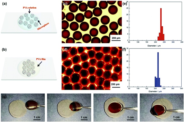
Since a plenty of Fe3O4@C magnetic particles were encapsulated in microspheres, these magnetic particles would form chain-like structures and display colors under external magnetic field.45 That makes microspheres hold great potential for mimicking some nature creatures which could tune their color according to external stimuli. In order to achieve this purpose, the microspheres were constrained in PVA film by evaporating water from PVA solution. Fig. 5(a) and (b) demonstrate the schematic illustration of microspheres in PVA solution and PVA film, it can be predicted that the distance of each microspheres would become smaller as the evaporation of water in PVA solution. Fig. 5(c) shows the optical macroscope image of the microspheres dispersed in PVA solution, the microspheres were uniformly dispersed in PVA solution. However, after PVA solution was dried and formed a film, the microspheres in the film are closing packed, but compared to the spheres in PVA solution, the shapes of microspheres are no longer spherical, as shown in Fig. 5(d). Furthermore, the sizes of these spheres get smaller after PVA solution was dried (Fig. 5(e) and (f)). The film could dynamically tune its color under magnetic field, the magnetic field intensity was 0.22 T. It displayed brown color when it is away from the magnet, while as the film moved to the magnet from one side to the other side, the color of the film changed from brown to red, as shown in Fig. 5(g) and Video S1.† The film displayed green color at the edge of the magnet and red color in the center of the magnet, which may result from the edge and the center of magnet have different magnetic field intensity, the magnetic field intensity at the edge is stronger than it in center, induced the distance between each magnetic particle in chain structures reduced and resulted in the film displaying green color at the edge of the magnet.
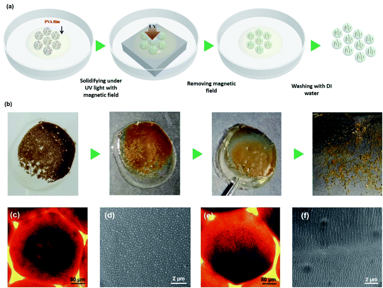
Due to the microspheres displaying structural color under external magnetic field, it inspired us a new method to fabricate microspheres with fixed structural colors. Fig. 6(a) shows a schematic illustration to the preparation of structural colored microspheres. Microspheres and PVA solution were collected in a Petri dish, because a plenty of magnetic particles were dispersed in microspheres, if the microspheres were polymerized directly in PVA solution under external magnetic field, microspheres will move to the edge of magnet and stacked together due to the un-uniform magnetic field of a magnet, resulting in microsphere generate uncontrollable color. To solve this problem, PVA solution was dried to form a film under room temperature. Thereafter, the film was transformed to an external magnetic field and then polymerized under UV light for 30 seconds. Then a structural colored film which composed of microspheres was obtained. Finally, the whole film was put into water to dissolve PVA, after PVA was completely dissolved in water, the polymerized microspheres were separated from the solution and the microspheres with fixed structural color were obtained. Fig. 6(b) shows digital photos in each process during the preparation of microspheres with fixed structure colors. The microspheres dispersed in PVA solution and displayed brown colors in the absence of magnetic field. After PVA solution was dried, microspheres were constrained in PVA film. The film displayed color under magnetic field, but the color is not the same as the film was put on the edge of magnet. After the film was move to the center of magnet, the color becomes uniform. At this time, the whole sample was transform to UV light to polymerize and the microspheres with structural color were obtained after polymerization.
The structural color of microspheres results from the inner micro-structural of Fe3O4@C magnetic particles.46 Fig. 6(c) shows the optical microscope image of microspheres in the absence of magnetic field and Fig. 6(e) shows the microspheres in the presence of magnetic field. It can be clearly seen that magnetic particles dispersed in microspheres randomly when there is no magnetic field. While the magnetic particles formed one dimensional chain like structures immediately when an external magnetic field was applied. If the microspheres were polymerized under UV light without an external magnetic field, it can be predicted that the magnetic particles would randomly distribute in microspheres. According to this assumption, we measured the SEM image of microspheres polymerized without magnetic field, it can be clearly observed that the particles were randomly existed on the surface of microspheres no chain-like structures were observed, as shown in Fig. 6(d). In contrary, if the microspheres were polymerized under magnetic field, magnetic particles would form chain-like structures. Fig. 6(f) is the SEM image of the microspheres which were polymerized under magnetic field, chain-like structures composed of magnetic particles were observed. The chain-like structures on the bottom of microspheres are denser than on the top, the same phenomenon was also observed inside the microspheres, as shown in Fig. S5.† The reason of this phenomenon may result from during the polymerization of microspheres, the magnet was put under the bottom of microspheres, magnetic particles intend to move to the bottom of microspheres under the driven of magnetic field during the chain-like structure formation, resulting in the number of chains in the bottom of microspheres more than above.
4. Conclusions
In summary, we demonstrated synthesis of monodisperse magnetochromatic microspheres in a microfluidic device. The size of microspheres could be controlled by the flow rates and microspheres with larger sizes are more likely to form close packed structures. Furthermore, the microspheres can be constrained in the PVA film after the PVA solution was dried and displayed brilliant, tunable structural color in the presence of external magnetic field. Moreover, microspheres could also be polymerized under UV light and have fixed structural color when using an external magnetic field during the polymerization. The microspheres fabricated in this work may find utility in displays as well as forgery protection and mimic smart color changing creatures in nature.Conflicts of interest
The authors declare that they have no conflict of interest.Acknowledgements
We gratefully acknowledge the financial support by the National Key R & D Program of China (2020YFC1910305), State Key Laboratory for Modification of Chemical Fibers and Polymer Materials, Donghua University (KF2014). The Opening Project of Key Laboratory of Clean Dyeing and Finishing Technology of Zhejiang Province, Project Number: QJRZ2104. Dr S. Shang thanks the Fundamental Research Funds for the Central Universities (17D310601) and the China Scholarship Council.References
- E. S. Goerlitzer, R. N. Klupp Taylor and N. Vogel, Adv. Mater., 2018, 30, 1706654 CrossRef PubMed.
- Y. J. Zhao, Z. Y. Xie, H. C. Gu, C. Zhu and Z. Z. Gu, Chem. Soc. Rev., 2012, 41, 3297–3317 RSC.
- Y. C. Li, Q. S. Fan, X. H. Wang, G. J. Liu, L. Q. Chai, L. Zhou, J. Shao and Y. D. Yin, Adv. Funct. Mater., 2021, 2010746 CrossRef CAS.
- Y. L. Ko, H. P. Tsai, K. Y. Lin, Y. C. Chen and H. Yang, J. Colloid Interface Sci., 2017, 487, 360–369 CrossRef CAS PubMed.
- Z. Cai, N. L. Smith, J. T. Zhang and S. A. Asher, Anal. Chem., 2015, 87, 5013–5025 CrossRef CAS PubMed.
- W. Liu, L. R. Shang, F. Y. Zheng, J. L. Qian, J. Lu, Y. J. Zhao and Z. Z. Gu, Small, 2014, 10, 88–93 CrossRef CAS PubMed.
- S. H. Kim, S. J. Jeon, W. C. Jeong, H. S. Park and S. M. Yang, Adv. Mater., 2008, 20, 4129–4134 CAS.
- S. Wu, B. Liu, X. Su and S. Zhang, J. Phys. Chem. Lett., 2017, 8, 2835–2841 CrossRef CAS PubMed.
- Z. Y. Yu, C. F. Wang, L. T. Ling, L. Chen and S. Chen, Angew. Chem., Int. Ed., 2012, 124, 2425–2428 CrossRef.
- Y. Zhao, X. Zhao, J. Hu, M. Xu, W. Zhao, L. Sun, C. Zhu, H. Xu and Z. Gu, Adv. Mater., 2009, 21, 569–572 CrossRef CAS PubMed.
- H. B. Zhang, C. Huang, N. S. Li and J. Wei, J. Colloid Interface Sci., 2021, 592, 249–258 CrossRef CAS PubMed.
- S. H. Kim, S. J. Jeon, G. R. Yi, C. J. Heo, J. H. Choi and S. M. Yang, Adv. Mater., 2008, 20, 1649–1655 CrossRef CAS.
- A. V. Singh, A. Rahman, N. V. G. Sudhir Kumar, A. S. Aditi, M. Galluzzi, S. Bovio, S. Barozzi, E. Montani and D. Parazzoli, Mater. Des., 2012, 36, 829–839 CrossRef CAS.
- Y. Wang, H. Cui, Q. Zhao and X. Du, Matter, 2019, 1, 626–638 CrossRef.
- J. Teyssier, S. V. Saenko, D. Marel and M. C. Millinkovitch, Nat. Commun., 2015, 6, 6368 CrossRef CAS PubMed.
- J. P. Ge and Y. D. Yin, Angew. Chem., Int. Ed., 2011, 50, 1492–1522 CrossRef CAS PubMed.
- S. L. Shang, P. Zhu, H. Z. Wang, Y. G. Li and S. Yang, ACS Appl. Mater. Interfaces, 2020, 12, 50844–50851 CrossRef CAS PubMed.
- M. Kumoda, M. Watanabe and Y. Takeoka, Langmuir, 2006, 22, 4403–4407 CrossRef CAS PubMed.
- H. R. Ma, M. X. Zhu, W. Luo, W. Li, K. Fang, F. Z. Mou and J. G. Guan, J. Mater. Chem. C, 2015, 3, 2848–2855 RSC.
- J. H. Holtz and S. A. Asher, Nature, 1997, 389, 829–832 CrossRef CAS PubMed.
- H. Saito, Y. Takeoka and M. Watanabe, Chem. Commun., 2003, 2126–2127 RSC.
- Q. Fu, H. Zhu and J. Ge, Adv. Funct. Mater., 2018, 28, 1804628 CrossRef.
- A. C. Sharma, T. Jana, R. Kesavamoorthy, L. J. Shi, M. A. Virji, D. N. Finegold and S. A. Asher, J. Am. Chem. Soc., 2004, 126, 2971–2977 CrossRef CAS PubMed.
- H. Fudouzi and T. Sawada, Langmuir, 2006, 22, 1365–1368 CrossRef CAS PubMed.
- B. Viel, T. Ruhl and G. P. Hellmann, Chem. Mater., 2007, 19, 5673–5679 CrossRef CAS.
- A. C. Arsenault, D. P. Puzzo, I. Manners and G. A. Ozin, Nat. Photonics, 2007, 1, 468–472 CrossRef CAS.
- J. Bibette, J. Magn. Magn. Mater., 1993, 122, 37–41 CrossRef CAS.
- X. Xu, G. Friedman, K. D. Humfeld, S. A. Majetich and S. A. Asher, Adv. Mater., 2001, 13, 1681–1684 CrossRef CAS.
- A. Tymoczko, M. Kamp, C. Rehbock, L. Kienle, E. Cattaruzza, S. Barcikowski and V. Amendola, Nanoscale Horiz., 2019, 4, 1326–1332 RSC.
- J. Johny, M. Kamp, O. Prymak, A. Tymoczko, U. Wiedwald, C. Rehbock, U. Schürmann, R. Popescu, D. Gerthsen, L. Kienle, S. Shaji and S. Barcikowski, J. Phys. Chem. C, 2021, 125, 9534–9549 CrossRef CAS.
- J. P. Ge, Y. X. Hu, M. Biasini, W. P. Beyermann and Y. D. Yin, Angew. Chem., Int. Ed., 2007, 46, 4342–4345 CrossRef CAS PubMed.
- J. P. Ge and Y. D. Yin, J. Mater. Chem., 2008, 18, 5041–5045 RSC.
- H. Wang, Y. B. Sun, Q. W. Chen, Y. F. Yu and K. Cheng, Dalton Trans., 2010, 39, 9565–9569 RSC.
- H. Wang, Q. W. Chen, Y. F. Yu, K. Cheng and Y. B. Sun, J. Phys. Chem. C, 2011, 115, 11427–11434 CrossRef CAS.
- W. Luo, H. R. Ma, F. Z. Mou, M. X. Zhu, J. D. Yan and J. G. Guan, Adv. Mater., 2014, 26, 1058–1064 CrossRef CAS PubMed.
- C. Chen, A. R. Abate, D. Lee, E. M. Terentjev and D. A. Weitz, Adv. Mater., 2009, 21, 3201–3204 CrossRef CAS.
- J. S. Xu, M. Shang, X. J. Ni and Y. H. Cao, ACS Appl. Nano Mater., 2020, 3, 8052–8059 CrossRef CAS.
- S. L. Shang, Q. H. Zhang, H. Z. Wang and Y. G. Li, J. Colloid Interface Sci., 2017, 485, 18–24 CrossRef CAS PubMed.
- H. Wang, Y. B. Sun, Q. W. Chen, Y. F. Yu and K. Cheng, Dalton Trans., 2010, 39, 9565–9569 RSC.
- J. W. Kim, A. S. Utada, A. F. Nieves, Z. Hu and D. A. Weitz, Angew. Chem., Int. Ed., 2007, 119, 1851–1854 CrossRef.
- H. Wang, Q. W. Chen, Y. F. Yu and K. Cheng, Dalton Trans., 2011, 40, 4810–4813 RSC.
- L. He, M. S. Wang, J. P. Ge and Y. D. Yin, Acc. Chem. Res., 2012, 45, 1431–1440 CrossRef CAS PubMed.
- S. L. Shang, Z. F. Liu, Q. H. Zhang, H. Z. Wang and Y. G. Li, J. Mater. Chem. A, 2015, 3, 11093–11097 RSC.
- F. Leal Calderon, T. Stora, O. Mondain Monval, P. Poulin and J. Bibette, Phys. Rev. Lett., 1994, 72, 2959–2962 CrossRef CAS PubMed.
- H. R. Ma, M. X. Zhu, W. Luo, W. Li, K. Fang, F. Z. Mou and J. G. Guan, J. Mater. Chem. C, 2015, 3, 2848–2855 RSC.
- S. L. Shang, Q. H. Zhang, H. Z. Wang and Y. G. Li, J. Colloid Interface Sci., 2016, 483, 11–16 CrossRef CAS PubMed.
Footnote |
| † Electronic supplementary information (ESI) available. See DOI: 10.1039/d1ra09028c |
| This journal is © The Royal Society of Chemistry 2022 |

