 Open Access Article
Single-layer membranes for organic solvent nanofiltration: a molecular dynamics simulation and comparative experimental study†
Xuejian Lia,
Yue Liu a,
Qiaohong Liu
 *b,
Zilong Zheng
 a and
Hongxia Guo*a
aKey Laboratory of Advanced Functional Materials of the Ministry of Education, College of Materials Science and Engineering, Beijing University of Technology, 100124 Beijing, P. R. China. E-mail: hxguo@bjut.edu.cn
bBeijing Key Laboratory for Green Catalysis and Separation, College of Environmental and Chemical Engineering, Beijing University of Technology, 100124 Beijing, P. R. China. E-mail: liuqiaohong@bjut.edu.cn
First published on 2nd March 2022
Abstract
Organic solvents are widely used in pharmaceutical and chemical industries. Their separation and recovery account for a large part of energy consumption and capital cost in many industrial processes. MoS2 membranes with varying pore sizes (0.6 nm pore with S atoms, 0.7 nm pore with Mo atoms, 1.3 nm pore with S atoms, 1.4 nm pore with Mo atoms) were investigated as organic solvent nanofiltration (OSN) membranes using molecular simulation in this study. The fluxes of five polar solvents (methanol, ethanol, propanol, acetonitrile and acetone) and a nonpolar solvent (n-hexane) were predicted. Although the 0.6 nm S pore has a smaller pore size, it has a better flux for some organic solvents than the 0.7 nm Mo pore. This selective behavior of molybdenum disulfide was confirmed by calculating the potential of mean force (PMF) of each solvent molecule. The PMFs show that polar solvents face a higher energy barrier through the pore, and greater resistance needs to be overcome. After testing the permeability of solvent by experiment and simulation, the flux changes of different solvents have the same trend in experiment and simulation. The solvent permeability was slightly affected in the presence of solute (acetaminophen), and MoS2 membranes with small pores demonstrated 100% rejection rate for acetaminophen. This study confirmed that pore chemistry and pore size play important roles in OSN, and MoS2 is a promising OSN membrane for the recovery of organic solvents.
1 Introduction
In comparison to traditional separation processes such as evaporation and distillation, membrane separation technology has been widely employed in industry due to its low energy consumption, space savings, good safety, and environmental friendliness.1,2 Chemical manufacture and pharmaceuticals usually involve the extraction of products from organic solutions in complex chemical environments, which necessitates the use of organic solvent nanofiltration (OSN) to help recover solvents, contaminants and products.3,4 Therefore, the OSN membrane should be stable in organic solvents for a relatively long time, and have a high permeability to allow the solvent to be processed quickly.5,6The most straightforward approach to enhance the permeability and reduce the preparation cost is to reduce the thickness of the separation membrane.7,8 Limited thin polyamide (PI) layers in a porous ultrafiltration membrane have been adopted for OSN membranes.9 However, the permeation flux was very low (2.3 L m−2 h−1 bar−1) when the membranes reached an acceptable rejection, 97%. Livingston et al.10 successfully reduced the thickness of the PI separation layer to 15 nm by regulating interfacial polymerization, and the acetonitrile transmittance of the membrane reached 114 L m−2 h−1 bar−1.
Another strategy to enhance the organic solvent permeability is to integrate continuous voids with a uniform diameter on the separation layer.11,12 For instance, the permeability of OSN membrane made of inherent microporous polymer (PIM) composed of rigid trapezoidal polymer chain to n-heptane is 19 L m−2 h−1 bar−1 for n-heptane.13 The conjugated microporous polymer derivative membrane with a thickness of 40 nm was prepared on polyacrylonitrile substrate, which provided 32 L m−2 h−1 bar−1 flux for hexane. Although the exploratory research on OSN membranes is successful,14 their usage in practical application is limited due to the strict preparation process requirements, sophisticated chemical synthesis and post-treatment technologies. Furthermore, the long-term durability of these membranes, which rely on the stability of the polymer matrix in various highly polar organic solvents, is a serious challenge.
As the novel two-dimensional materials developed, two-dimensional (2D) membranes can be exploited as competitive candidates for OSN applications.15,16 The two-dimensional separation membrane consists of several layers of nanosheets stacked parallel to each other with atomic layer thickness.17,18 Because of the voids between adjacent nanosheets, this unique structure results in uniform performance of transmission and separation.19–21 On the other hand, a single layer of nanosheets can essentially create component separation to achieve the minimum transport resistance and the maximum permeability.22,23 In practical applications, 2D laminates with thicknesses ranging from a few nanometers to tens of microns have been proven to be appropriate for a wide range of membrane processes, including gas separation, desalination and nanofiltration.24–27 The two-dimensional membranes combine the advantages of ultra-thin and narrow distribution channels, so they are considered as the prospective OSN membranes after proper modification.
Similar to graphene, inorganic two-dimensional transition metal sulfides have excellent mechanical strength and chemical stability, and have been assembled into 2D layered membranes.28,29 In comparison with graphene, monolayer MoS2 contains two types of atoms: molybdenum and sulfur where a Mo-atom-layer is sandwiched between two layers of S atoms as a single sandwiched S–Mo–S layer with van der Waals interactions. The bond length of Mo–S is 2.42 Å and the thickness of optimized lattice constant of MoS2 is 3.18 Å.30,31 MoS2 has a high mechanical strength and elastic modulus up to 270 GPa, which is similar to the structure of steel.32 The water flux of the membrane stacked with MoS2 nanosheets is approximately 5 times that of the graphene substrate membrane with the same thickness. Some recent work has described MoS2 related films for OSN applications. For example, it has been reported that glycerol supported MoS2 membranes can be utilized for organic solvent transfer.33 However, the organic solvent permeability of pure MoS2 membranes with clean two-dimensional channels has not been thoroughly investigated.
When nanopores are formed in MoS2, the charge of membrane surface changed, which plays an important role in water permeability and ion selectivity. The charges mainly depend on the fluid that flow through the pore, so their influence is not considered in the work. Perfect MoS2 without defects cannot penetrate any molecules due to its absence of pores. As a result, in order to construct molecular sieves from MoS2, it is necessary to drill holes of varying sizes in the middle of MoS2. Different sizes of MoS2 pore can be generated by high-speed heavy metal ions bombarding the surface of MoS2.23 Aluru et al. investigated DNA sequencing using MoS2 with nanopore in the center.34 Their molecular dynamics (MD) and density functional theory (DFT) results reveal that, compared with graphene, MoS2 is a promising nanomaterial for DNA sequencing technology, with faster and higher resolution recognition ability. Gravelle et al.35 recently discovered that the nozzle like structure of protein channel can improve the water permeability. Therefore, MoS2 with various central holes and structures can be used as a nozzle like structure for rapid water infiltration. The water or ion flux through MoS2 membrane increases according to the type and size of pore.36 As a result of size exclusion effect, very tiny thickness and pore structure MoS2 membrane is expected to exhibit excellent selectivity and permeability. As the membrane thickness increases, the solvent flux through the membrane decreases. As far as we know, there is no experimental or theoretical method to investigate the nanofiltration performance of pure MoS2 membrane.
In this study, we reported a molecular simulation study to explore the OSN performance of monolayer MoS2 membrane, considering four MoS2 nanofiltration membranes with different pore sizes and chemical properties and six organic solvents, including five polar solvents (methanol, ethanol, propanol, acetonitrile and acetone) and one non-polar solvent (n-hexane). Moreover, a model solute, acetaminophen (APAP), is used to test OSN performance.37,38 Furthermore, solvent flux, permeability and the interaction energy between solvent and membrane property were also discussed, followed by the study of the solute repulsion.
2 Method
2.1 Simulation details and atomic structures
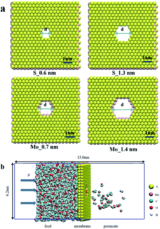
Because the pore structure has a significant impact on the performance of the separation process, OSN membranes shall have controllable pore size. According to that, we designed MoS2 membranes with different shapes and sizes nano-micropores. Four types of MoS2 of different nonfunctionalized pores were selected (Fig. 1), with the pore density of 2.6 × 10¹⁶ pore m−2, namely S_0.6 (0.6 nm pore with S atom, 14 S atoms and 9 Mo atoms were removed), Mo_0.7 (0.7 nm pore with Mo atom, 38 S atoms and 9 Mo atoms were removed), S_1.3 (1.3 nm pore with S atom, 38 S atoms and 24 Mo atoms were removed) and Mo_1.4 (1.4 nm pore with Mo atom, 74 S atoms and 24 Mo atoms were removed) respectively. Each of them has different chemical environments and pore sizes. Because the two-dimensional membrane we selected is only a single molecular layer thick and the channel type is relatively simplistic, the pore size is smaller than the experiment results (Fig. S1†). The simulation system includes a single-layer MoS2 nanosheet, which is placed in the center of the periodic unit and divides 2000 organic solvent molecules in the feed side. To prevent organic solvent overflow from the periodic structure, the boundaries of the model box on both sides are single-layer molybdenum disulfide molecules, at the same time, charged particles are added at the edge of the box to balance the system charge and keep the system charge neutral. The dimension of simulation box was 6.2 × 6.2 × 15 × 10−27 m3 and the periodic boundary condition were applied in three directions. The force field parameters of MoS2 were obtained from the previous research.37 All six solvents (methanol, ethanol, acetonitrile, acetone and hexane) and solutes (acetaminophen) were described by OPLS force field. All simulations are performed using Gromacs v.2018.3 software package and visualized using vmd1.9.3.The organic solvent is separated by external pressure of 0–100 MPa. As shown in Fig. 1b, a constant external force (0–3000 kJ mol−1 nm2) is applied to the single layer of MoS2 in the selected section of the simulation box in the Z direction to generate a pressure difference to the system (ΔP in Pa). In our system, the external constant force acts on the boundary monolayer molybdenum disulfide and applies corresponding pressure to the organic solvent to push the solvent through the central molybdenum disulfide membranes, which can move only in the Z direction. The area of the selected membrane is a = 3.84 × 10⁻¹⁷ m2 with n = 2000 organic solvent molecules (see Fig. 1b). The external constant force called pressure driven flow is defined as:
 | (1) |
MD simulation was carried out according to the following steps: (1) the system was subjected to energy minimization by the steepest descent method with a maximum step of 0.5 Å and a force tolerance of 1000 kJ mol−1 nm−1, the energy of the simulation system is minimized in 50![[thin space (1/6-em)]](https://www.rsc.org/images/entities/char_2009.gif) 000 steps in zero temperature. (2) The final coordinates of the previous step are balanced for 1 ns at 1 atm and 298 K. Langevin thermostat was used to stabled the temperature of system at 298 K. (3) To further equilibrate, MD simulation was done in the NVT and NPT ensemble for 2 ns. (4) The non-equilibrium simulation of 5 ns under different induced pressures is carried out in NVT ensemble.
000 steps in zero temperature. (2) The final coordinates of the previous step are balanced for 1 ns at 1 atm and 298 K. Langevin thermostat was used to stabled the temperature of system at 298 K. (3) To further equilibrate, MD simulation was done in the NVT and NPT ensemble for 2 ns. (4) The non-equilibrium simulation of 5 ns under different induced pressures is carried out in NVT ensemble.
The MoS2 film is fixed in the middle position to avoid the vertical displacement during MD simulation. A 12 Å cut-off line is used for short-range interaction and Ewald interaction is employed for long-range interaction. It should be noted that the pressure gradient applied here is one order of magnitude higher than the actual OSN, which is very common in MD simulation. The purpose is to reduce thermal noise and enhance signal-to-noise ratio in nanosecond simulation time scale. MoS2 atoms were frozen during the simulation. The LJ interaction is calculated with the cut-off value of 14 Å, and the electrostatic interaction is calculated with the particle grid method. The time step is 2 fs, and the trajectory is saved every 50 ps. All simulations are carried out with Gromacs v.2018.03. The atomic interaction is simulated by Leonard Jones (LJ) and electrostatic potential
 | (2) |
 | (3) |
The potential energy parameters of MoS2 plate are similar to those of intermediate film. In order to test the performance of OSN, the inhibition of acetaminophen was further simulated. For this case, 0.05 M acetaminophen was added to the left ventricle. It should be noted that the common dye molecules were not used to test solute rejection. This is because the size of dye molecules is generally greater than 10 Å, and can't pass through the pore at all. On the contrary, the molecular dynamics diameter of acetaminophen is 6.2 Å (calculated in the visualization software Vesta39), which is equal to the pore size.
2.2 Membrane separation performance
![[thin space (1/6-em)]](https://www.rsc.org/images/entities/char_2009.gif) :
:![[thin space (1/6-em)]](https://www.rsc.org/images/entities/char_2009.gif) 32 were fully dissolved in deionized water into homogeneous precursor solution with concentration of 1.7 g L−1. Then, the cleaned white ceramic tubular substrates were completely submerged into the precursor solution under vacuum until no bubbles were produced. Subsequently, the precursor solution together with the tubular ceramic substrate was transferred into a Teflon autoclave and carried out hydrothermal reaction at 220 °C for 30 h. After the reaction ended, the autoclave was naturally cooled down. The black MoS2 tubular ceramic membrane was taken out and washed with water and anhydrous ethanol alternately.
32 were fully dissolved in deionized water into homogeneous precursor solution with concentration of 1.7 g L−1. Then, the cleaned white ceramic tubular substrates were completely submerged into the precursor solution under vacuum until no bubbles were produced. Subsequently, the precursor solution together with the tubular ceramic substrate was transferred into a Teflon autoclave and carried out hydrothermal reaction at 220 °C for 30 h. After the reaction ended, the autoclave was naturally cooled down. The black MoS2 tubular ceramic membrane was taken out and washed with water and anhydrous ethanol alternately.3 Results and discussion
From this simulation study, the nanofiltration performance of MoS2 membrane for organic solvents was tested. Before describing the simulation results, the assumptions need to be clarified: (1) it is assumed that the MoS2 structure is stable and rigid in solvent. If the flexible models is used, the solvent permeability and solute rejection may be affected by structural changes. (2) In order to obtain OSN flux in a short time, a higher pressure has been used in simulation process; the predicted flux and permeability are consequently in high-end products. (3) The thickness of the film investigated is only a few nanometers, which is much thinner than the thickness of the experimental sample. Therefore, the fluxes of simulation results may much higher than the experimental measurements. (4) Membrane fouling is an important factor in the practical application of membrane, which has an adverse impact on the performance of membrane. The simulation here focuses on simulating the performance of the membrane in a very short time without considering pollution.3.1 Flux
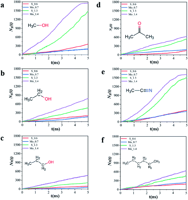
In pressure gradient ΔP, the solvent has a net flow from left ventricle to right. Fig. 2 depicts the number of organic solvent molecules (NS) penetrating the four MoS2 membranes at P = 100 MPa, and the number of organic solvent molecules pass through the MoS2 molecular layer increases linearly with time. The permeability of all solvents is nearly constant until all solvent molecules pass through the pore, and the permeability is calculated as eqn (4).From the slope of NS ∼ t in Fig. 2, it can be calculated by calculating the solvent flux JS
 | (4) |
As shown in Fig. 3, the fluxes of six organic solvent (methanol, ethanol, propanol, n-hexane, acetonitrile and acetone) passing through MoS2 membrane with two kinds of pore sizes S and Mo have been listed. In Fig. 2a and e, the NS generally increases linearly with time after a certain time lag. This happens because the relative molecular mass of methanol and acetonitrile is low, thus solvent molecules need to fill in the space between solvent and membrane. For the same solvent, the time lag depends on the organic solvent type. When the pore size is very small, methanol, ethanol and propanol have a smaller flux with Mo_0.7 membrane comparing with S_0.6 membrane. However, the flux of n-hexane is 75 × 104 kg m−2 h−1 in the pore Mo_0.7, which is significantly higher than 57 × 104 kg m−2 h−1 that in pore S_0.6. The flux of acetonitrile and acetone is almost the same for the two small holes. When the pore size increase, the flux of six solvents in pore Mo_1.4 are all higher than in pore S_1.3. As mentioned earlier, pores with S atoms (0.6 nm, 1.3 nm) compared with pores with Mo atoms (0.7 nm, 1.4 nm), the flux of solvent does not simply follow the molecular dynamics diameter (Table S2† shows molecular dynamics diameter of organic solvent). Obviously, the pore type plays an important role in the interaction between solvents when solvents pass through membrane pores.
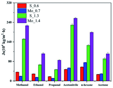 | ||
| Fig. 3 Flux of solvent through molybdenum disulfide membrane (orange: S_0.6, cyan: Mo_0.7, purple: S_1.3, yellow: Mo_1.4). | ||
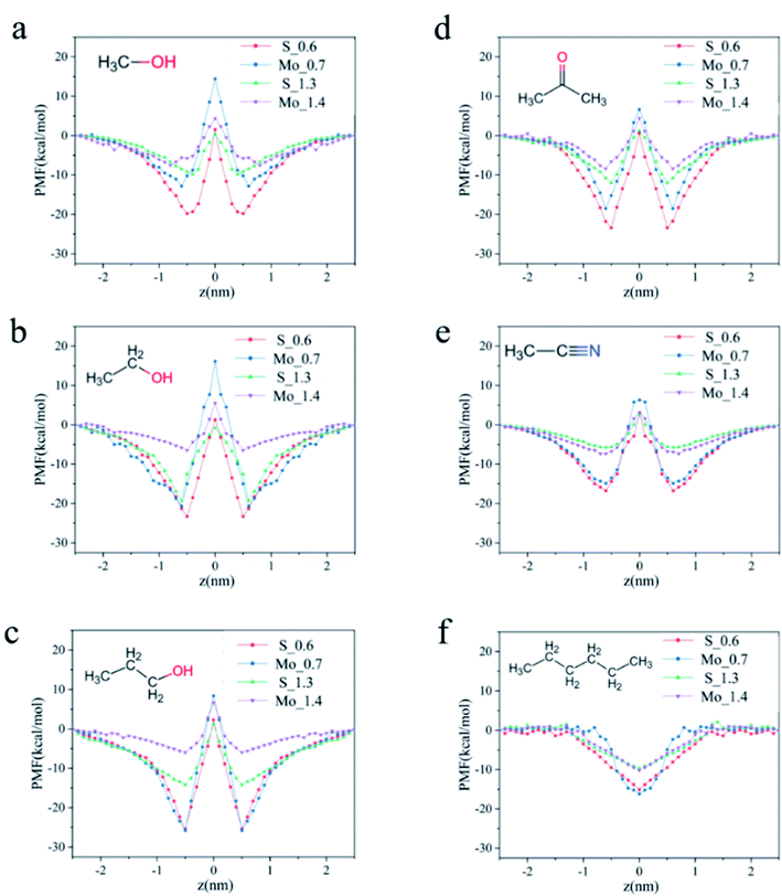
3.2 The potential of mean force (PMF) of six solvents through the four MoS2 membranes
Because the flux of organic solvents does not simply follow the increase of pore size and solvent molecular dynamics diameter, we speculate that this is related to the repulsive force between the solvents and pores when passing through the pores. Therefore, we calculated the PMF when the solvent passes through the pores. PMF refers to the method of umbrella sampling to drag the organic solvent molecules from the position perpendicular to the pore diameter along the Z direction to gradually pass through the MoS2 nanofiltration membrane at the center. At this time, the change of the interaction energy after the ensemble average of the system is the potential of mean force.Fig. 4a–c PMFs shows that according to the order of molecular diameter, the energy barrier of the three solvents passing through the pore is also low to high. Among the three alcohol solvents, the energy barrier of methanol is always the lowest and that of propanol is the highest, because larger solvent diameter will produce greater interaction force when passing through the membrane, resulting in higher resistance. Moreover, different types of pore sizes also have different trends. In the S hole, when the energy barrier is close to the membrane, the degree of mutual attraction is much higher than that of Mo hole. Near the center of the membrane pore, the interaction energy increases gradually. Finally, it becomes positive, but the degree of exclusion is less than that of Mo hole. This is because the membrane pores are charged. The combined action of van der Waals force and Coulomb interaction leads to the strong attraction of solvent molecules by S atoms on the membrane and repulsion with Mo atoms.
3.3 Influence of pressure on flux
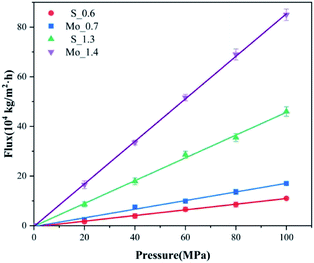
Fig. 5 shows the change of the flux of propanol solvent through four kinds of membrane with different pores under different pressures. Between 0 MPa to 100 MPa, the flux changes linearly with pressure. In the same aperture, the main factor affecting the flux is pressure, and the flux is directly proportional to pressure. With the increase of pressure, the flux increases, and the ratio between the flux and pressure remains stable. The pressure ranges from 20 MPa to 100 MPa and the flux also increase 5-fold. The permeability coefficient is usually considered constant for pure materials, depending on the membrane material and the nature of the solvent used in the liquid phase.3.4 Solvent permeability
 | (5) |
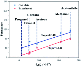
Fig. 6 plots the correlation between the correlation of permeability and solvent properties in MoS2 membrane (1.3 nm with S-pore) in simulation and experiment. In the simulation, except hexane, a fairly good correlation was found. It is not surprising that hexane does not conform well to formula (5). Due to the linear shape of n-hexane, its molecular diameters dm,s overestimate the cross-sectional size of n-hexane. In the experiment, six solvents were found to have a good correlation. There is a very good correlation between simulation and calculation. The simulation results of organic solvent flux show that our theoretical calculation have the almost the same trend with experimental results, which means that our calculation results are in good agreement with the experiment and have good practical significance.
3.5 Solute rejection (C8H9NO2)
The rejection rate of solute is an important aspect of membrane performance. In order to further examine the OSN performance of MoS2 membrane, 5% was added into the solvent. Acetaminophen is a type of small drug molecule whose molecular dynamics diameter is 6.2 Å, and its structure is mentioned in Table S2.† In the process of using acetaminophen, a large number of acetaminophen will be mixed into methanol solvents, but there is still no effective method to extract and recover it.45Based on the calculation, the membranes (S_0.6 and Mo_0.7) can completely reject acetaminophen in all six solvents, and the solvent permeability was calculated using PS = JS/ΔP when acetaminophen was present (Table 1). The permeability of the solvent decreases slightly when adding acetaminophen. Although acetaminophen cannot pass through the membrane, it would affect the passage of solvent molecules, albeit very slightly.
| Solvent | S_0.6 | Mo_0.7 | S_1.3 | Mo_1.4 | ||||
|---|---|---|---|---|---|---|---|---|
| Fluxes | Rejection rate | Fluxes | Rejection rate | Fluxes | Rejection rate | Fluxes | Rejection rate | |
| Methanol | 31 | 100% | 17 | 100% | 158 | 91% | 202 | 87% |
| Ethanol | 24 | 11 | 56 | 88% | 84 | 83% | ||
| Propanol | 8 | 6 | 43 | 93% | 67 | 95% | ||
| Acetonitrile | 41 | 48 | 192 | 86% | 234 | 92% | ||
| n-Hexane | 45 | 65 | 132 | 85% | 184 | 90% | ||
| Acetone | 21 | 26 | 75 | 88% | 87 | 86% | ||
4 Conclusion
A molecular simulation study is reported to examine solvent permeation and solute rejection through MoS2 membranes with different pore sizes and edge atoms. The results indicated that in the small pores (S_0.6, Mo_0.7), the energy barrier between the solvent and pore edge atoms is relatively high and determine the solvent flux, especially for the polar solvents. When the pore size increases to 1.3 nm (S) and 1.4 nm (Mo), the energy barrier decreases, and the flux is mainly controlled by the pore size. In the presence of solute, acetaminophen, the MoS2 membranes show a negligible change in solvent permeances and perfect rejection. The solvent permeances and the solvent properties were combined by a molecule model, and good correlations are found. A very good consistency is obtained after combining it with the experiment. The simulation study provides a good research direction and ideas of various solvents in different MoS2 membrane, reveals the important role of pore size and chemical environment in solvent penetration, and is helpful to the rational design of high-performance OSN membrane.Data availability
The data used to support the findings of this study are available from the corresponding author upon reasonable request.Author contributions
Xuejian Li: conceptualization, methodology, software, data, curation, writing – original draft, visualization, investigation. Qiaohong Liu: supervision, validation, writing – review & editing. Yue Liu: methodology, software, writing – review & editing. Zilong Zheng: writing – review & editing. Hongxia Guo: writing – review & editing.Conflicts of interest
The authors declared that we have no conflicts of interest to this work. We declare that we do not have any commercial or associative interest that represents a conflict of interest in connection with the work submitted.Acknowledgements
This work was financially supported by National Natural Science Foundation of China (21878003, 22178007).References
- J. C. Lin and A. G. Livingston, Nanofiltration membrane cascade for continuous solvent exchange, Chem. Eng. Sci., 2007, 62, 2728–2736, DOI:10.1016/j.ces.2006.08.004.
- P. Marchetti, M. F. Jimenez Solomon, G. Szekely and A. G. Livingston, Molecular Separation with Organic Solvent Nanofiltration: A Critical Review, Chem. Rev., 2014, 114, 10735–10806, DOI:10.1021/cr500006j.
- D. Zedel, M. Kraume and A. Drews, Modelling and prediction of organic solvent flux and retention of surfactants by organic solvent nanofiltration, J. Membr. Sci., 2017, 544, 323–332, DOI:10.1016/j.memsci.2017.09.041.
- P. Vandezande, L. E. M. Gevers and I. F. J. Vankelecom, Solvent resistant nanofiltration: separating on a molecular level, Chem. Soc. Rev., 2008, 37, 365–405, 10.1039/B610848M.
- X. Li, S. De Feyter, D. Chen, S. Aldea, P. Vandezande and F. Du Prez, et al., Solvent-Resistant Nanofiltration Membranes Based on Multilayered Polyelectrolyte Complexes, Chem. Mater., 2008, 20, 3876–3883, DOI:10.1021/cm703072k.
- M. Sairam, X. X. Loh, Y. Bhole, I. Sereewatthanawut, K. Li and A. Bismarck, et al., Spiral-wound polyaniline membrane modules for organic solvent nanofiltration (OSN), J. Membr. Sci., 2010, 349, 123–129, DOI:10.1016/j.memsci.2009.11.039.
- S. Karan, S. Samitsu, X. Peng, K. Kurashima and I. Ichinose, Ultrafast Viscous Permeation of Organic Solvents Through Diamond-Like Carbon Nanosheets, Science, 2012, 335, 444–447, DOI:10.1126/science.1212101.
- S. P. Surwade, S. N. Smirnov, I. V. Vlassiouk, R. R. Unocic, G. M. Veith and S. Dai, et al., Water desalination using nanoporous single-layer graphene, Nat. Nanotechnol., 2015, 10, 459–464, DOI:10.1038/nnano.2015.37.
- M. F. Jimenez Solomon, Y. Bhole and A. G. Livingston, High flux membranes for organic solvent nanofiltration (OSN)—Interfacial polymerization with solvent activation, J. Membr. Sci., 2012, 423–424, 371–382, DOI:10.1016/j.memsci.2012.08.030.
- S. Karan, Z. Jiang and A. G. Livingston, Sub-10 nm polyamide nanofilms with ultrafast solvent transport for molecular separation, Science, 2015, 348, 1347–1351, DOI:10.1126/science.aaa5058.
- T. P. Moneypenny, N. P. Walter, Z. Cai, Y. Miao, D. L. Gray and J. J. Hinman, et al., Impact of Shape Persistence on the Porosity of Molecular Cages, J. Am. Chem. Soc., 2017, 139, 3259–3264, DOI:10.1021/jacs.7b00189.
- Y. Du, H. Yang, J. M. Whiteley, S. Wan, Y. Jin and S. H. Lee, et al., Ionic Covalent Organic Frameworks with Spiroborate Linkage, Angew. Chem., Int. Ed., 2016, 55, 1737–1741, DOI:10.1002/anie.201509014.
- P. Gorgojo, S. Karan, H. C. Wong, M. F. Jimenez-Solomon, J. T. Cabral and A. G. Livingston, Ultrathin Polymer Films with Intrinsic Microporosity: Anomalous Solvent Permeation and High Flux Membranes, Adv. Funct. Mater., 2014, 24, 4729–4737, DOI:10.1002/adfm.201400400.
- B. Liang, H. Wang, X. Shi, B. Shen, X. He and Z. A. Ghazi, et al., Microporous membranes comprising conjugated polymers with rigid backbones enable ultrafast organic-solvent nanofiltration, Nat. Chem., 2018, 10, 961–967, DOI:10.1038/s41557-018-0093-9.
- J. Wang, Z. Yuan, X. Wu, Y. Li, J. Chen and Z. Jiang, Beetle-Inspired Assembly of Heterostructured Lamellar Membranes with Polymer Cluster–Patterned Surface for Enhanced Molecular Permeation, Adv. Funct. Mater., 2019, 29, 1900819, DOI:10.1002/adfm.201900819.
- C. Chen, J. Wang, D. Liu, C. Yang, Y. Liu, R. S. Ruoff and W. Li, Functionalized boron nitride membranes with ultrafast solvent transport performance for molecular separation, Nat. Commun., 2018, 9, 1902, DOI:10.1038/s41467-018-04294-6.
- Y. Kang, Y. Xia, H. Wang and X. Zhang, 2D Laminar Membranes for Selective Water and Ion Transport, Adv. Funct. Mater., 2019, 29, 1902014, DOI:10.1002/adfm.201902014.
- Z. Zheng, R. Grünker and X. Feng, Synthetic Two-Dimensional Materials: A New Paradigm of Membranes for Ultimate Separation, Adv. Mater., 2016, 28, 6529–6545, DOI:10.1002/adma.201506237.
- G. Liu, W. Jin and N. Xu, Graphene-based membranes, Chem. Soc. Rev., 2015, 44, 5016–5030, 10.1039/c4cs00423j.
- R. R. Nair, H. A. Wu, P. N. Jayaram, I. V. Grigorieva and A. K. Geim, Unimpeded Permeation of Water Through Helium-Leak-Tight Graphene-Based Membranes, Science, 2012, 335, 442–444, DOI:10.1126/science.1211694.
- Y. Kang, Y. Xia, H. Wang and X. Zhang, 2D Laminar Membranes for Selective Water and Ion Transport, Adv. Funct. Mater., 2019, 29, 1902014, DOI:10.1002/adfm.201902014.
- L. Wang, M. S. H. Boutilier, P. R. Kidambi, D. Jang, N. G. Hadjiconstantinou and R. Karnik, Fundamental transport mechanisms, fabrication and potential applications of nanoporous atomically thin membranes, Nat. Nanotechnol., 2017, 12, 509–522, DOI:10.1038/nnano.2017.72.
- Y. Zhao, Y. Xie, Z. Liu, X. Wang, Y. Chai and F. Yan, Two-Dimensional Material Membranes: An Emerging Platform for Controllable Mass Transport Applications, Small, 2014, 10, 4521–4542, DOI:10.1002/smll.201401549.
- H. Huang, Y. Ying and X. Peng, Graphene oxide nanosheet: an emerging star material for novel separation membranes, J. Mater. Chem., 2014, 2, 13772–13782, 10.1039/c4ta02359e.
- F. Perreault, A. Fonseca de Faria and M. Elimelech, Environmental applications of graphene-based nanomaterials, Chem. Soc. Rev., 2015, 44, 5861–5896, 10.1039/C5CS00021A.
- K. A. Mahmoud, B. Mansoor, A. Mansour and M. Khraisheh, Functional graphene nanosheets: the next generation membranes for water desalination, Desalination, 2015, 356, 208–225, DOI:10.1016/j.desal.2014.10.022.
- L. Wang, M. S. H. Boutilier, P. R. Kidambi, D. Jang, N. G. Hadjiconstantinou and R. Karnik, Fundamental transport mechanisms, fabrication and potential applications of nanoporous atomically thin membranes, Nat. Nanotechnol., 2017, 12, 509–522, DOI:10.1038/nnano.2017.72.
- S. Bertolazzi, J. Brivio and A. Kis, Stretching and Breaking of Ultrathin MoS2, ACS Nano, 2011, 5, 9703–9709, DOI:10.1021/nn203879f.
- L. Sun, Y. Ying, H. Huang, Z. Song, Y. Mao and Z. Xu, et al., Ultrafast Molecule Separation through Layered WS2 Nanosheet Membranes, ACS Nano, 2014, 8, 6304–6311, DOI:10.1021/nn501786m.
- B. Guo, S. Jiang, M. Tang, K. Li, S. Sun and P. Chen, et al., MoS2 Membranes for Organic Solvent Nanofiltration: Stability and Structural Control, J. Phys. Chem. Lett., 2019, 10, 4609–4617, DOI:10.1021/acs.jpclett.9b01780.
- G. Eda, H. Yamaguchi and D. Voiry, Photoluminescence from chemically exfoliated MoS2, Nano Lett., 2011, 11, 5111–5116, DOI:10.1021/nl201874w.
- S. Jiang, A. Y. K. Koh, K. H. Chong and S. Zhang, Opening organic solvent pathways by molybdenum disulfide in mixed matrix membranes for molecular separation, J. Membr. Sci., 2019, 585, 60–66, DOI:10.1016/j.memsci.2019.05.021.
- L. Sun, H. Huang and X. Peng, Laminar MoS2 membranes for molecule separation, Chem. Commun., 2013, 49, 10718, 10.1039/c3cc46136j.
- A. B. Farimani, K. Min and N. R. Aluru, DNA Base Detection Using a Single-Layer MoS2, ACS Nano, 2014, 8, 7914–7922, DOI:10.1021/nn5029295.
- S. Gravelle, L. Joly, F. Detcheverry, C. Ybert, C. Cottin-Bizonne and L. Bocquet, Optimizing water permeability through the hourglass shape of aquaporins, Proc. Natl. Acad. Sci. U. S. A., 2013, 110, 16367–16372, DOI:10.1073/pnas.1306447110.
- M. E. Suk and N. R. Aluru, Water Transport through Ultrathin Graphene, J. Phys. Chem. Lett., 2010, 1, 1590–1594, DOI:10.1021/jz100240r.
- V. Sresht, A. Govind Rajan, E. Bordes, M. S. Strano, A. A. H. Pádua and D. Blankschtein, Quantitative Modeling of MoS2–Solvent Interfaces: Predicting Contact Angles and Exfoliation Performance using Molecular Dynamics, J. Phys. Chem. C, 2017, 121, 9022–9031, DOI:10.1021/acs.jpcc.7b00484.
- F. A. Silva, T. Sintra, S. P. M. Ventura and J. A. P. Coutinho, Recovery of paracetamol from pharmaceutical wastes, Sep. Purif. Technol., 2014, 122, 315–322, DOI:10.1016/j.seppur.2013.11.018.
- K. Momma and F. Izumi, VESTA3 for three-dimensional visualization of crystal, volumetric and morphology data, J. Appl. Crystallogr., 2011, 44, 1272–1276, DOI:10.1107/S0021889811038970.
- F. Perreault, D. F. A. Fonseca and M. Elimelech, Environmental applications of graphene-based nanomaterials, Chem. Soc. Rev., 2015, 44, 5861–5896, 10.1039/c5cs00021a.
- Y. I. Jhon, C. Kim, Y. T. Byun, J. H. Lee and Y. M. Jhon, Facile large-area fabrication of highly selective and permeable few-layered graphene: a molecular dynamics study, Carbon, 2019, 155, 369–378, DOI:10.1016/j.carbon.2019.08.082.
- J. P. K. Abal, R. F. Dillenburg, M. H. Köhler and M. C. Barbosa, Molecular Dynamics Simulations of Water Anchored in Multilayered Nanoporous MoS2 Membranes: Implications for Desalination, ACS Appl. Nano Mater., 2021, 4, 10467–10476, DOI:10.1021/acsanm.1c01982.
- M. K. Borg and J. M. Reese, Multiscale simulation of enhanced water flow in nanotubes, MRS Bull., 2017, 42, 294–299, DOI:10.1557/mrs.2017.59.
- Y. Xu, J. Lin, C. Gao, B. Van der Bruggen, Q. Shen and H. Shao, et al., Preparation of High-Flux Nanoporous Solvent Resistant Polyacrylonitrile Membrane with Potential Fractionation of Dyes and Na2 SO4, Ind. Eng. Chem. Res., 2017, 56, 11967–11976, DOI:10.1021/acs.iecr.7b03409.
- N. Kouki, R. Tayeb and M. Dhahbi, Recovery of acetaminophen from aqueous solutions using a supported liquid membrane based on a quaternary ammonium salt as ionophore, Chem. Pap., 2014, 68, 457–464, DOI:10.2478/s11696-013-0479-5.
Footnote |
| † Electronic supplementary information (ESI) available. See DOI: 10.1039/d1ra09061e |
| This journal is © The Royal Society of Chemistry 2022 |

