
 Open Access Article
 This Open Access Article is licensed under a Creative Commons Attribution-Non Commercial 3.0 Unported Licence
Ni3FeN functionalized carbon nanofibers boosting polysulfide conversion for Li–S chemistry†
Lufu Xu,
Huani Li,
Genfu Zhao,
Yongjiang Sun,
Han Wang and
Hong Guo *
*
School of Materials and Energy, Yunnan University, Kunming 650091, China. E-mail: guohong@ynu.edu.cn
First published on 2nd March 2022
Abstract
Limiting the shuttle effect of polysulfides is an important means to realizing high energy density lithium–sulfur batteries (Li–S). In this study, an efficient electrocatalyst (CNFs@Ni3FeN) is synthesized by anchoring Ni3FeN in the carbon nanofibers (CNFs). The CNFs@Ni3FeN shows electrocatalytic activity and enhances the conversion of polysulfides. After assembling a battery, a high initial capacity (1452 mA h g−1) and favorable long-time cycling stability (100 cycles) with a capacity retention rate of 83% are obtained by the electrocatalysis of Ni3FeN. Compared with unmodified CNFs, the cycling stability of CNFs@Ni3FeN can be greatly improved. The catalytic mechanism is further deduced by X-ray photoelectron spectroscopy (XPS). Our work will inspire the rational design of CNFs@support hybrids for various electrocatalysis applications.
Introduction
In the past decades, the demand for high energy density energy storage devices has promoted the development of many energy storage systems, such as lithium-ion battery technology, sodium-ion battery technology and so on. The most representative energy storage system is the lithium-ion battery.1–3 Lithium-ion batteries are also widely used in our society because of their relatively high energy density.4 However, lithium-ion batteries have some shortcomings, such as low abundance of lithium resources, uneven distribution and low energy density, so their further development is limited.5 Previous research shows that lithium–sulfur batteries (Li–S battery) have an energy density as high as 2600 W h kg−1 and a theoretical specific capacity of 1675 mA h g−1. So, Li–S battery is promising to become the next generation energy storage system after lithium-ion battery.6As the positive active material, sulfur (S8) participates in the charge compensation in the process of charge and discharge in Li–S battery. The discharge process of Li–S battery can be divided into three stages.6,7 In the first stage, sulfur (S8) is reduced to form S42− by step-by-step sequence reduction of soluble polysulfide ions, and the reaction speed is fast (voltage platform ∼2.3 V vs. Li/Li+). It is worth noting that various intermediate polysulfides (Li2Sx, x = 8–4) will be formed in this process. These polysulfides are highly dissolved in organic electrolytes, resulting in irreversible capacity loss. For example, high-order polysulfides are conversed into low-order polysulfides (Li2S or Li2S2) and deposited the surface of lithium anode. This process will reduce the utility of active material sulfur and the coulombic efficiency in charge–discharge process. In the second stage, the soluble lithium polysulfide Li2S4 is reduced to insoluble Li2S2, and the voltage platform is 2 V vs. Li/Li+. This process is controlled by the solid phase nucleation reaction, so the reaction rate is slow. In the third stage, solid phase Li2S2 is reduced to solid phase Li2S, which is controlled by solid phase diffusion of Li ions, so the reaction rate is slow.8 The capacity contribution of these three stages is 25%, 25% and 50%, respectively.9 Compared with the discharge process, the charge process is relatively simple. In the cyclic voltammetry (CV) of sulfur or polysulfide electrodes, typically there is only one anodic peak.10 Although the lithium–sulfur battery has high specific capacity and rich mineral resources, its development still faces many challenges, such as low conductivity of positive active material sulfur (S8),11 shuttle effect of polysulfides, slow reaction kinetics and large volume change in charge–discharge process.
At present, there are mainly the following strategies to overcome the problem of polysulfide shuttle effect: (1) physically limiting the active material sulfur to porous conductive materials;12–14 (2) chemical adsorption the polysulfides with defective carbon,15–17 transition metal oxides,18–20 MXene,21,22 transition metal nitride,23 and so on; (3) microstructure design with graphene24–27 or carbon materials28–30 to prepare free-standing electrodes or three-dimensional electrodes;30–32 and (4) introducing a conductive intermediate layer between separator and cathode to alleviate the shuttle effect of the polysulfides.33–38 Among them, transition metal nitride has attracted considerable attention in Li–S batteries because the catalysts efficiently accelerate the conversion of the lithium polysulfides and actually inhibit polysulfide shuttling. Especially for the Ni3FeN material with highly exposed active sites and high electrical conductivity has been developed to enhance the electrocatalytic activity in oxygen evolution reaction (OER).39 Considering that sulfur and oxygen have similar electrochemical redox mechanisms, Ni3FeN is also used as a sulfur promoter to promote the conversion of polysulfides.
In this work, we use CNFs@Ni3FeN composites to alleviate the shuttle effect of polysulfides in the charge–discharge process, and enhance the coulomb efficiency and cycle stability of Li–S battery in the charge–discharge process. The Ni3FeN in the material can implement the adsorption of soluble polysulfides produced in the process of charge and discharge and alleviate the shuttle effect in the process of cycle. At the same time, it can also catalyze the conversion of polysulfides to S22− and the oxidation of Li2S during charging, so as to reduce the existence time of soluble polysulfides and alleviate the shuttle effect of polysulfides.40–42 The carbon nanofibers in the materials provide a three-dimensional supporting conductive skeleton for the cathode materials. Therefore, through the synergistic effect of Ni3FeN and CNFs, high-performance Li–S battery can be achieved.
Materials
All the chemical materials and characterized apparatus are described in the ESI.†Results and discussions
tThe crystal structural characteristics of CNFs, Ni3FeN and CNFs@Ni3FeN were detected by X-ray diffraction (XRD) analysis, illustrated in Fig. 1a. From the diagram, we can observe that the peak position of the Ni3FeN material coincides well with that of the Ni3FeN standard card (PDF: 00-050-1434), indicating that the ternary phase Ni3FeN has been synthesized successfully.39 The characteristic peak of Ni3FeN is strong and sharp, implying that the synthesized Ni3FeN has high crystallinity. Comparing the XRD spectra of CNFs, Ni3FeN and CNFs@Ni3FeN, we find that CNFs@Ni3FeN not only has the characteristic peak of Ni3FeN crystal, but also has the same peak as CNFs, certifying that Ni3FeN and CNFs were successfully compounded by electrospinning. Fig. 1b shows the Raman spectra of CNFs, Ni3FeN and CNFs@Ni3FeN. It can be observed that there are two typical G-band peaks in CNFs and CNFs@Ni3FeN materials, which are located at 1354.17 cm−1 and 1587.34 cm−1 respectively. The peak-to-intensity ratio of D-band and G-band is 1.05, proving that the structure of CNFs is mainly short-range ordered graphite structure.43 The low graphitization degree of the carbon in CNFs@Ni3FeN can promote the migration of Li+ during the cycle.42 In addition, we can find that there is a Raman peak of Ni3FeN (546.988 cm−1) in CNFs@Ni3FeN materials, which further proves that CNFs@Ni3FeN is successfully synthesized. As depicted in Fig. 1c–e, the scanning electron microscopy (SEM) and transmission electron microscopy (TEM) images show that Ni3FeN nanoparticles are well dispersed on the carbon nanofiber. From the SEM images of CNFs and CNFs@Ni3FeN, it can be observed that the average diameter of CNFs and CNFs@Ni3FeN is about 300 nm. According to TEM figure, Ni3FeN nanoparticles are crystallized on the inner of carbon nanofiber. The d-spacings of 0.215 nm correspond to the (111) planes of Ni3FeN.39 This further verifies that Ni3FeN is well compounded with carbon nanofibers.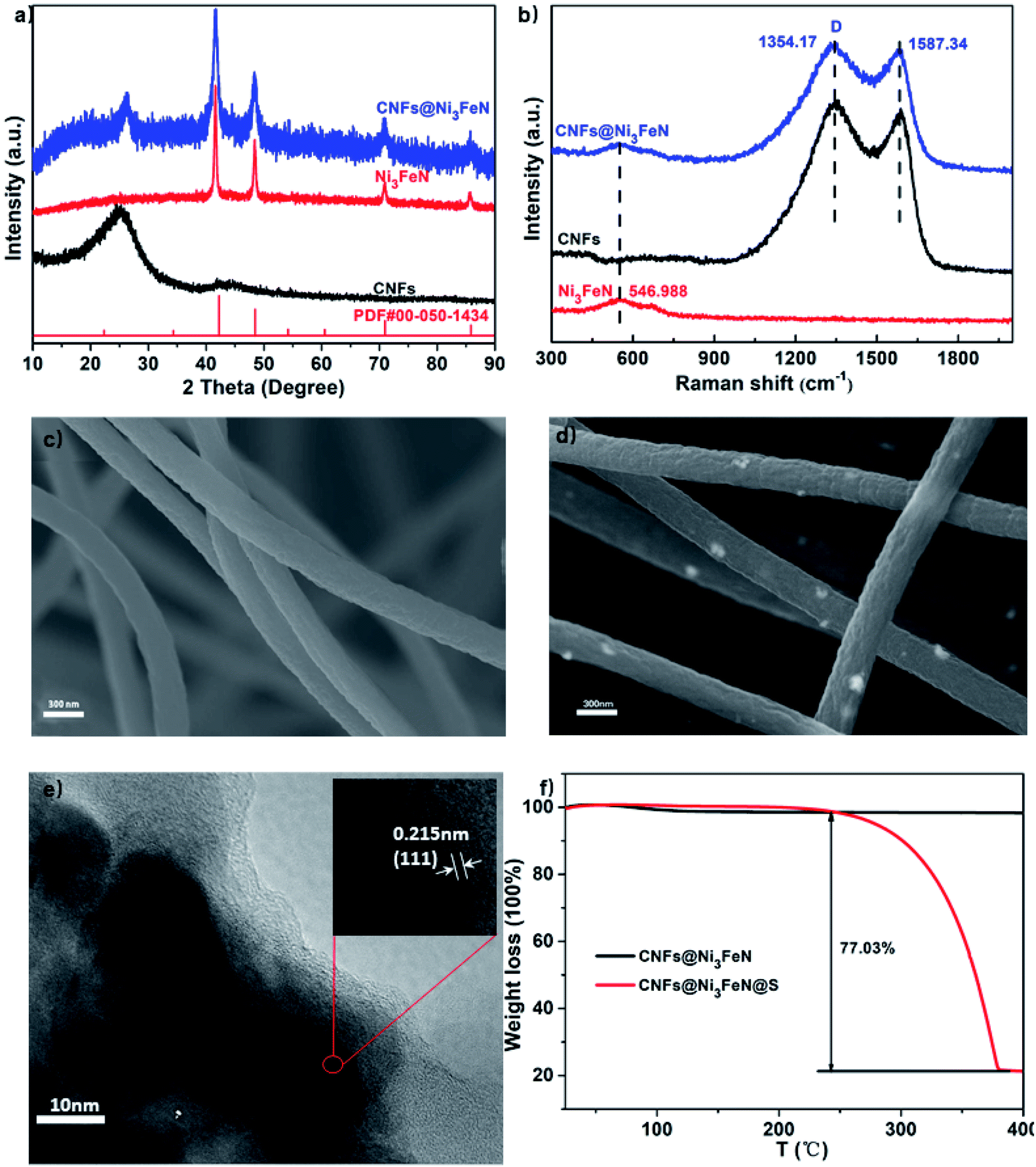 | ||
| Fig. 1 (a) XRD patterns of Ni3FeN, CNFs and CNFs@Ni3FeN. (b) Raman spectra of Ni3FeN, CNFs and CNFs@Ni3FeN. SEM images of (c) CNFs and (d) CNFs@Ni3FeN. (e) TEM images of CNFs@ Ni3FeN. (f) TGA curves of CNFs@Ni3FeN and CNFs @Ni3FeN@S. | ||
For the purpose of exploring the load of sulfur in the host materials, the thermogravimetric analysis (TGA) of CNFs@Ni3FeN@S was collected and shown in Fig. 1f. It can be seen that the mass loss of CNFs@Ni3FeN@S sample is 77.03 wt%, but there is no obvious mass change of CNFs@Ni3FeN sample. The result reveals that the load of sulfur is about 77.03 wt%. In order to further analyze the total surface area and micropore volume of the CNFs and CNFs@Ni3FeN, the nitrogen adsorption–desorption isotherms were carried out. The type of curve in Fig. S1a† is type IV, which manifests that there are abundant mesoporous structures. From the analysis, the total surface area and micropore volume of the CNFs are 228.521 m2 g−1, 0.1017 cm3 g−1, respectively and the CNFs@Ni3FeN are 107.265 m2 g−1, 0.04857 cm3 g−1, respectively. As exhibited in the Fig. S1b,† the pore size distribution of CNFs@Ni3FeN is between 2 and 5 nm, while that of CNFs is about 15 nm. It turns out that both materials are porous structure. The porous structure is conducive to electrolyte infiltration into the material and the transport of lithium ion in the electrode material.44 Moreover, the relatively small specific surface area and pore size in CNFs@Ni3FeN can inhibit the bulky volumetric corrosion of the CNFs@Ni3FeN@S cathode occurring in the conversion reaction that might enhance the energy storage performances of CNFs@Ni3FeN.45
The valence states of elements in CNFs@Ni3FeN and CNFs were determined by X-ray photoelectron spectroscopy (XPS), shown in Fig. 2a–d. From Fig. 2a, there are obvious peaks of Fe, Ni, N and S in Ni3FeN and CNFs@Ni3FeN/Li2S4. The C and O elements with strong peaks in the picture may come from the raw materials in the process of Ni3FeN preparation. Fig. 2b and c are the XPS spectrum of Ni 2p and Fe 2p, respectively. The result reveals that the element of Ni is in the state of Ni2+ and Ni0, and the element of Fe is in the state of Fe3+ and Fe0. The existence of Ni2+ and Fe3+ may be related to the existence of some inevitable surface oxide layer in Ni3FeN.46–48 Compared with CNFs@Ni3FeN, the Ni 2p3/2 spectrum of CNFs@Ni3FeN/Li2S4 shifts to the direction of low binding energy (0.3 eV). These changes indicate that there is a charge transfer between Ni and S in Li2S4, and the electrons on S atoms are transferred to Ni atoms.49 In the Fe 2p3/2 spectrum of Fig. 2c, we can see that all the peaks in the Fe 2p3/2 spectrum (712.6 eV) of CNFs@Ni3FeN after polysulfide adsorption shift 0.4 eV to the direction of low binding energy, revealing that electrons are transferred from S atoms in Li2S4 to Fe atoms.49 Fig. 2d is the N 1s spectrum. After the reaction with polysulfides, the N 1s spectrum of CNFs@Ni3FeN/Li2S4 shifts significantly to higher binding energy than that of CNFs@Ni3FeN (0.6 eV). This phenomenon may result from the transfer of electrons from N atom to metal atoms. The XPS spectra of Ni 2p3/2, Fe 2p3/2 and N 1s show that Ni3FeN has a strong adsorption effect on polysulfides.
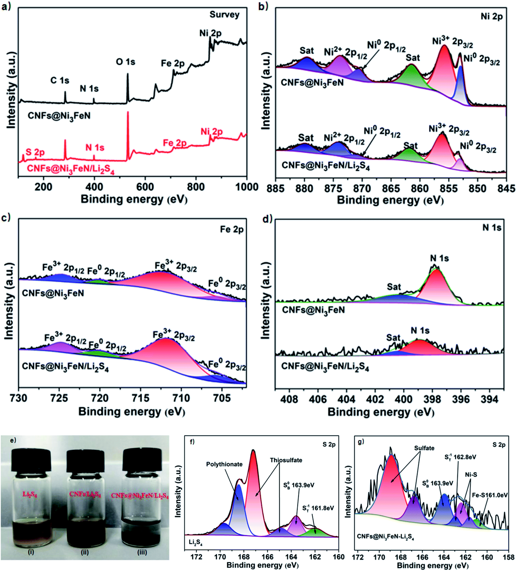 | ||
| Fig. 2 (a–d) XPS spectra of the CNFs and CNFs@Ni3FeN. (a) Full spectrum, (b) Ni 2p, (c) Fe 2p, (d) N 1s. (e) Photographs of a Li2S4 solution (i) Li2S4 solution added with CNFs (ii) and Li2S4 solution added with CNFs@Ni3FeN (iii). (f) XPS S 2p spectra of Li2S4 and (g) XPS S 2p spectra of CNFs@Ni3FeN/Li2S4. | ||
In addition, static visible light adsorption experiments were implemented to visualize the anchoring ability between Ni3FeN and polysulfides. CNFs and CNFs@Ni3FeN with the same specific surface area were immersed into the Li2S4 electrolyte of 1.5 mL. After that, they were placed in a glove box for 3 h. We can observe in Fig. 2e that the color of Li2S4 solution immersed with CNFs is still yellow and does not fade, while the color of Li2S4 solution immersed with CNFs@Ni3FeN has completely faded. The results show that Ni3FeN has a strong adsorption effect on polysulfides. For further studying the interaction between CNFs@Ni3FeN@S and Li2S4, XPS studies on Li2S4 and CNFs@Ni3FeN@S–Li2S4 were carried out. As shown in Fig. 2f, the peaks at 161.8 eV and 163.6 eV in the S 2p spectrum correspond to terminal (ST−1) and bridged (SB0) sulfur atoms. However, when CNFs@Ni3FeN@S was added to the Li2S4 solution in Fig. 2g, ST−1 (162.8 eV) and SB0 (163.9 eV) in the S 2p spectrum shifted to varying degrees, and they moved 1.0 and 0.3 eV, respectively. At the same time, there are new peaks at 162.5/161.9 eV and 161.1 eV, which belongs to Ni–S bond and Fe–S bond, respectively. The appearance of these two bonds indicate that CNFs@Ni3FeN@S has a strong chemisorption to Li2S4.50,51 In addition, we can see that there is a sulfate peak at 165–168 eV and a thiosulfate peak at 168 eV, which may be related to the disproportionation of intermediate Li2Sx to produce higher and lower oxidized substances.52–55 Moreover, we can find that the peaks of these two places are weakened to some extent after the addition of CNFs@Ni3FeN, which disclose that CNFs@Ni3FeN can better catalyze the transformation of Li2S4 to low-valent reduced state. The above analyses imply that the electrocatalyst was successfully prepared and shown good adsorption and catalytic capacity for polysulfide.
The electrochemical storage properties of CNFs@S and CNFs@Ni3FeN@S electrodes were studied by using coin cell and lithium sheet as counter electrode. The CV curves of CNFs@S and CNFs@Ni3FeN@S are shown in Fig. 3a. The typical cathode peaks appear at 2.0 V and 2.3 V, which is attributed to the formation and conversion of long-chain polysulfides to Li2S. The continuous anodizing peaks at 2.3–2.5 V are the transition from Li2S/Li2S2 to polysulfide. CNFs@Ni3FeN@S shows the sharpest and highest anodic peak, which implies that the conversion process from Li2S to polysulfides is more thorough. At the same time, the CNFs@Ni3FeN also shows better catalytic behavior to promote the transformation of polysulfides. Fig. 3b presents the CV curves of the five circles of CNFs@Ni3FeN@S. It can be seen that the coincidence of cathode peak and anode peak is very good. The result demonstrates that the Li–S battery assembled with CNFs@Ni3FeN@S as positive electrode has excellent charge–discharge cycle stability and the reversible reaction is more favorable from S8 to Li2S/Li2S2.56
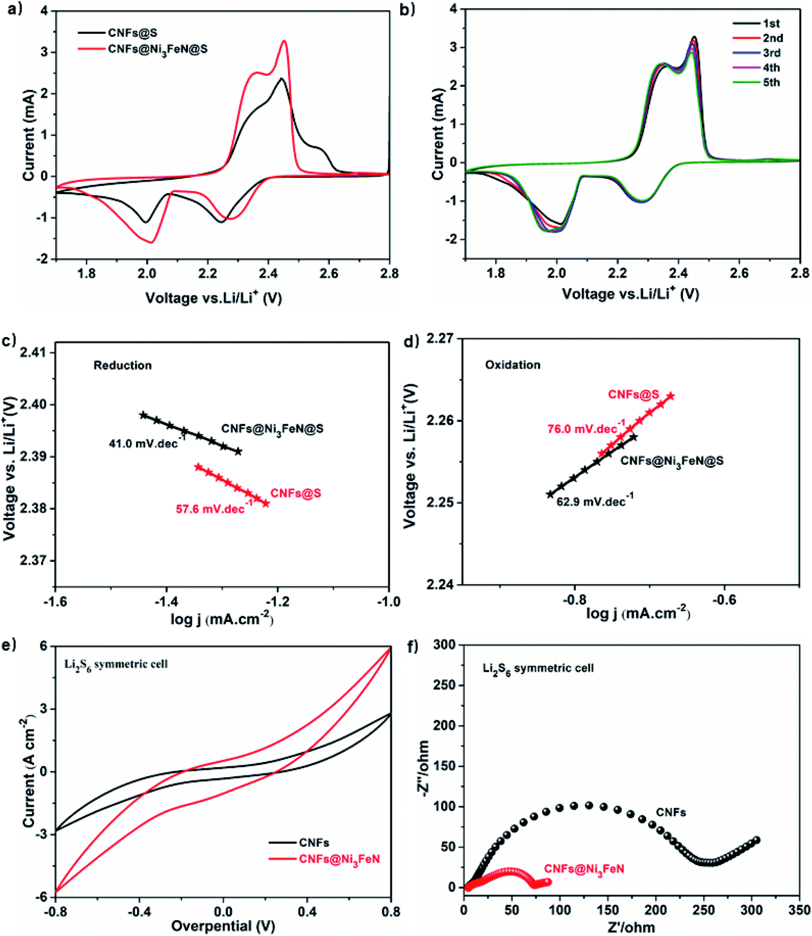 | ||
| Fig. 3 CV curves at the scan rate of 0.1 mV s−1 in a potential window from 1.7 to 2.8 V of (a) the CNFs@Ni3FeN and CNFs@Ni3FeN@S electrodes and (b) the first five cycles of CNFs@Ni3FeN@S. Tafel plots of the (c) first reduction peak and (d) the oxidation peak. (e) CV curves of symmetric cells and (f) EIS Nyquist plots obtained from CNFs@Ni3FeN and CNFs@Ni3FeN@S electrodes. | ||
To further quantitatively analyze the catalytic kinetic rate of polysulfide conversion process, the Tafel slopes of the first reduction and oxidation processes were obtained in Fig. 3c and d, respectively. For the first reduction peak, the Tafel slopes of CNFs@S and CNFs@Ni3FeN@S are 41.0 and 57.6 mV dec−1, respectively. For the first oxidation peak, the Tafel slopes of CNFs@S and CNFs@Ni3FeN@S are 76.0 and 62.9 mV dec−1, respectively. The Tafel slope of lithium–sulfur battery assembled with in situ synthesized CNFs@Ni3FeN@S as positive electrode is relatively small, which clearly confirms that the reaction between liquid polysulfide and solid sulfur is easier, and the electrocatalyst Ni3FeN promotes the conversion of polysulfide.57 Symmetrical cells were assembled for CV and Electrochemical impedance spectroscopy (EIS) tests to further explore the catalytic performance of CNFs and CNFs@Ni3FeN. As showcase in Fig. 3e, when the voltage bias is 0.8 V, the redox current response of CNFs@Ni3FeN is nearly twice that of CNFs, implying that Ni3FeN can enhance the conversion efficiency and electrochemical reversibility of polysulfides to Li2S.58 The EIS measurements of CNFs and CNFs@Ni3FeN are analyzed in Fig. 3f. It can be seen from the Nyquist diagram that the EIS of CNFs and CNFs@Ni3FeN are composed of high frequency semicircle, intermediate frequency semicircle and an inclined low frequency line. The high frequency semicircle is related to the charge transfer resistance (Rct), the intermediate frequency semicircle is related to the establishment of the solid electrolyte interface (SEI) film resistance (Rs) produced during the irreversible aggregation of insoluble low-order polysulfide, and the inclined line is related to the Warburg impedance (We) of Li+ diffusion in the electrode.59 Obviously, compared with the CNFs@S electrode, the CNFs@Ni3FeN@S displays smaller the solid electrolyte interface (SEI) film resistance (Rs). The excellent interface impedance results suggest that due to the existence of Ni3FeN, the amount of irreversible insoluble low-order polysulfide at the electrode interface is reduced, thereby resulting in enhanced the transformation of insoluble low-order polysulfide to higher-order polysulfide and S8. Above results consistently demonstrate the efficient adsorption and catalytic polysulfide conversion capability of CNFs@Ni3FeN.
The galvanostatic charge–discharge curves of CNFs@S and CNFs@Ni3FeN@S composites at 0.1C (1C = 1675 mA h g−1) are witnessed in Fig. 4a. At ∼2.3 V and ∼2.1 V, the two typical high discharge platforms and low discharge platforms refer to the adsorption level and conversion level of polysulfides, respectively.42 This is consistent with the analysis of the CV curve. CNFs@Ni3FeN@S composite nanostructure materials can provide high initial discharge capacity of 1406.5 mA h g−1, which is much higher than that of CNFs@S (1156.9 mA h g−1). The charge–discharge platform of CNFs@Ni3FeN@S is longer, indicating that it has the ability to improve the utilization of active materials and promote the conversion between solid sulfide and long-chain polysulfides. In addition, to further confirm that CNFs@Ni3FeN@S can better adsorb and catalyze polysulfides, we used CNFs@Ni3FeN@S and CNFs@S as positive electrodes to test the charge–discharge cycle performance of the battery at 0.1C. As can be seen from Fig. 4b, the initial discharge specific capacities of CNFs@Ni3FeN@S and CNFs@S are 1452.2 mA h g−1 and 1156.9 mA h g−1, respectively. After 100 cycles, the discharge specific capacities of CNFs@Ni3FeN@S and CNFs@S are 1203.7 mA h g−1 and 358.2 mA h g−1, respectively. The results imply that the Ni3FeN can effectively adsorb polysulfides and catalyze the conversion of polysulfides.
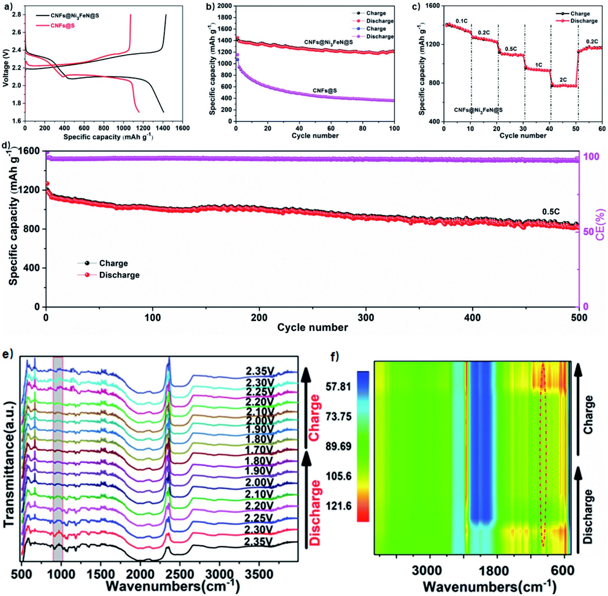 | ||
| Fig. 4 (a) Reversible discharge/charge voltage profiles at 0.1C of CNFs@S and CNFs@Ni3FeN@S electrodes. (b) Cycle performances at 0.1C of CNFs@S and CNFs@Ni3FeN@S electrodes. (c) Rate performances of CNFs@Ni3FeN@S electrodes at 0.1C, 0.2C, 0.5C, 1C and 2C rates. (d) Long-term cycling performances of CNFs@Ni3FeN electrodes at 0.5C. (e) In situ FT-IR spectra of CNFs@Ni3FeN@S cathode at different discharge and charge states. (f) Contour and response surface analysis corresponding to the discharge and charge processes. | ||
The rate performance of CNFs@Ni3FeN@S cathode at various current rates from 0.1C to 2C was evaluated in the voltage range from 1.7 to 2.8 V. As depicted in Fig. 4c, the discharge capacities of CNFs@Ni3FeN@S cathode exhibit 1372.4, 1261.9, 1097.1, 937.1, and 781.2 mA h g−1 at 0.1, 0.2, 0.5, 1, and 2C, respectively. Impressively, once the current rate switched back to 0.2C, the CNFs@Ni3FeN@S cathode can harvest an excellent capacity of 1129.5 mA h g−1, which is attributed to the robust and stable structure.40 Long-cycle stability is very important for commercial applications of lithium batteries. For evaluate the long-term cycle behavior of CNFs@Ni3FeN@S, batteries using CNFs@Ni3FeN@S cathodes are cycled at 0.5C for 500 times in Fig. 4d. After 500 cycles, the discharge capacity descends from 1267 mA h g−1 to 812 mA h g−1, and the coulombic efficiency remains above 99%. The result displays that the CNFs@Ni3FeN@S cathode has excellent long cycle performance, which can be attributed to the catalysis and adsorption of Ni3FeN.
Furthermore, in order to fully understand the mechanism of action, we assembled the Li–S half cells for in situ Fourier transform infrared (FT-IR) measurement. The cathode material was CNFs@Ni3FeN@S, the anode was lithium plate, the positive current collector was carbon paper, and the separator was Celgard polypropylene (PP) membrane. The electrolyte was 1 M LiTFSI dissolved in DME/DOL (VDME![[thin space (1/6-em)]](https://www.rsc.org/images/entities/char_2009.gif) :VDOL = 1:1) solution, in addition, 2% LiNO3 was used as additive. The result is illustrated in Fig. 4e and f. It is worth noticing that the intensities of the Li–S peak located at 933 cm−1 decrease and nearly disappear at the end of discharging, followed by reappearance upon charging, signifying the excellent reversibility of electrochemical reactions and effective restriction of polysulfides within the CNFs@Ni3FeN@S‖Li@Li cell.
:VDOL = 1:1) solution, in addition, 2% LiNO3 was used as additive. The result is illustrated in Fig. 4e and f. It is worth noticing that the intensities of the Li–S peak located at 933 cm−1 decrease and nearly disappear at the end of discharging, followed by reappearance upon charging, signifying the excellent reversibility of electrochemical reactions and effective restriction of polysulfides within the CNFs@Ni3FeN@S‖Li@Li cell.
Conclusions
In summary, we proved that Ni3FeN can be used as a highly efficient cathode catalyst for Li–S cells. In this paper, CNFs@Ni3FeN materials with special micro-nano composite structure were synthesized in situ by electrospinning. Electrochemical tests and other physical characterizations show that, compared with CNFs, CNFs@Ni3FeN not only has strong chemisorption effect on polysulfide intermediates, but also can significantly accelerate the transformation of polysulfides and alleviate the shuttle effect of Li–S cells. Our work explores a new way for the design and development of cathode materials for high-performance Li–S batteries, as well as providing a more reasonable method for the commercialization of Li–S cells.Conflicts of interest
The authors declare no competing financial interest.Acknowledgements
The authors acknowledge financial support provided by the National Natural Science Foundation of China (52064049), the Key National Natural Science Foundation of Yunnan Province (2018FA028 and 2019FY003023), International Joint Research Center for Advanced Energy Materials of Yunnan Province (202003AE140001), Key Laboratory of Solid State Ions for Green Energy of Yunnan University (2019).References
- G. Zhao, H. Li, Z. Gao, L. Xu, Z. Mei, S. Cai, T. Liu, X. Yang, H. Guo and X. Sun, Adv. Funct. Mater., 2021, 2101019 CrossRef CAS.
- G. Zhao, L. Xu, J. Jiang, Z. Mei, Q. An, P. Lv, X. Yang, H. Guo and X. Sun, Nano Energy, 2022, 92, 106756 CrossRef CAS.
- Q. An, H. Wang, G. Zhao, S. Wang, L. Xu, H. Wang, Y. Fu and H. Guo, Energy Environ. Sci., 2022 DOI:10.1002/eem2.12345.
- G. Zhao, Y. Zhang, Z. Gao, H. Li, S. Liu, S. Cai, X. Yang, H. Guo and X. Sun, ACS Energy Lett., 2020, 5, 1022–1031 CrossRef CAS.
- W. Weng, G. Liu, L. Shen and X. Yao, J. Power Sources, 2021, 512, 230485 CrossRef CAS.
- K. Kumaresan, Y. Mikhaylik and R. E. White, J. Electrochem. Soc., 2008, 155, A576 CrossRef CAS.
- H. Yamin and E. Peled, J. Power Sources, 1983, 9, 281–287 CrossRef CAS.
- H. Xu, S. Guo, W. Li and P. Yu, Sci. Rep., 2015, 5, 1–12 Search PubMed.
- X. Zhou, T. Liu, G. Zhao, X. Yang and H. Guo, Energy Storage Mater, 2021, 40, 139–149 CrossRef.
- H. Yamin, J. Penciner, A. Gorenshtain, M. Elam and E. Peled, J. Power Sources, 1985, 14, 129–134 CrossRef CAS.
- Y. Yang, G. Zheng and Y. Cui, Chem. Soc. Rev., 2013, 42, 3018–3032 RSC.
- W. Zhou, Y. Yu, H. Chen, F. J. DiSalvo and H. D. Abruña, J. Am. Chem. Soc., 2013, 135, 16736–16743 CrossRef CAS PubMed.
- J. S. Lee, J. Jun, J. Jang and A. Manthiram, Small, 2017, 13, 1602984 CrossRef PubMed.
- S. K. Park, J. Lee, T. Hwang, B. Jang and Y. Piao, ACS Appl. Mater. Interfaces, 2017, 9, 2430–2438 CrossRef CAS PubMed.
- X. Song, S. Wang, Y. Bao, G. Liu, W. Sun, L. Ding, H. Liu and H. Wang, J. Mater. Chem. A, 2017, 5, 6832–6839 RSC.
- Z. Liu, J. Li, J. Xiang, S. Cheng, H. Wu, N. Zhang, L. Yuan, W. Zhang, J. Xie and Y. Huang, Phys. Chem. Chem. Phys., 2017, 19, 2567–2573 RSC.
- W. Zhou, B. Guo, H. Gao and J. B. Goodenough, Adv. Energy Mater., 2016, 6, 1502059 CrossRef.
- H. Wang, C. Fan, Y. Zheng, X. Zhang, W. Li, S. Liu, H. Sun, J. Zhang, L. Sun and X. Wu, Chem.–Eur. J., 2017, 23, 9666–9673 CrossRef CAS PubMed.
- Q. Sun, K. Chen, Y. Liu, Y. Li and M. Wei, Chem.–Eur. J., 2017, 23, 16312–16318 CrossRef CAS PubMed.
- X. He, H. Hou, X. Yuan, L. Huang, J. Hu, B. Liu, J. Xu, J. Xie, J. Yang and S. Liang, Sci. Rep., 2017, 7, 1–9 CrossRef PubMed.
- X. Liang, A. Garsuch and L. F. Nazar, Angew. Chem., 2015, 127, 3979–3983 CrossRef.
- M. Xiang, H. Wu, H. Liu, J. Huang, Y. Zheng, L. Yang, P. Jing, Y. Zhang, S. Dou and H. Liu, Adv. Funct. Mater., 2017, 27, 1702573 CrossRef.
- Z. Cui, C. Zu, W. Zhou, A. Manthiram and J. B. Goodenough, Adv. Mater., 2016, 28, 6926–6931 CrossRef CAS PubMed.
- X. Zhao, H. Wang, G. Zhai and G. Wang, Chem.–Eur. J., 2017, 23, 7037–7045 CrossRef CAS PubMed.
- K. Zhang, K. Xie, K. Yuan, W. Lu, S. Hu, W. Wei, M. Bai and C. Shen, J. Mater. Chem. A, 2017, 5, 7309–7315 RSC.
- S. H. Chung and A. Manthiram, Adv. Mater., 2018, 30, 1705951 CrossRef PubMed.
- M. R. Kaiser, Z. Ma, X. Wang, F. Han, T. Gao, X. Fan, J. Wang, H. K. Liu, S. Dou and C. Wang, ACS Nano, 2017, 11, 9048–9056 CrossRef CAS PubMed.
- M. Li, R. Carter, A. Douglas, L. Oakes and C. L. Pint, ACS Nano, 2017, 11, 4877–4884 CrossRef CAS PubMed.
- L. Sun, D. Wang, Y. Luo, K. Wang, W. Kong, Y. Wu, L. Zhang, K. Jiang, Q. Li and Y. Zhang, ACS Nano, 2016, 10, 1300–1308 CrossRef CAS PubMed.
- A. Mentbayeva, A. Belgibayeva, N. Umirov, Y. Zhang, I. Taniguchi, I. Kurmanbayeva and Z. Bakenov, Electrochim. Acta, 2016, 217, 242–248 CrossRef CAS.
- F. Wu, E. Zhao, D. Gordon, Y. Xiao, C. Hu and G. Yushin, Adv. Mater., 2016, 28, 6365–6371 CrossRef CAS PubMed.
- B. Xu, H. Wang, Q. Zhu, N. Sun, B. Anasori, L. Hu, F. Wang, Y. Guan and Y. Gogotsi, Energy Storage Mater, 2018, 12, 128–136 CrossRef.
- J. Y. Hwang, H. M. Kim, S. K. Lee, J. H. Lee, A. Abouimrane, M. A. Khaleel, I. Belharouak, A. Manthiram and Y. K. Sun, Adv. Energy Mater., 2016, 6, 1501480 CrossRef.
- H. Shao, W. Wang, H. Zhang, A. Wang, X. Chen and Y. Huang, J. Power Sources, 2018, 378, 537–545 CrossRef CAS.
- H. Peng, J. Huang, X. Liu, X. Cheng, W. Xu, C. Zhao, F. Wei and Q. Zhang, J. Am. Chem. Soc., 2017, 139, 8458–8466 CrossRef CAS PubMed.
- A. Paolella, D. Laul, V. Timoshevskii, W. Zhu, S. Marras, G. Bertoni, A. S. Wahba, G. Girard, C. Gagnon and L. Rodrigue, J. Phys. Chem. C, 2018, 122, 1014–1023 CrossRef CAS.
- S. Lim, R. Lilly Thankamony, T. Yim, H. Chu, Y. Kim, J. Mun and T. Kim, ACS Appl. Mater. Interfaces, 2015, 7, 1401–1405 CrossRef CAS PubMed.
- M. Shaibani, A. Akbari, P. Sheath, C. D. Easton, P. C. Banerjee, K. Konstas, A. Fakhfouri, M. Barghamadi, M. M. Musameh and A. S. Best, ACS Nano, 2016, 10, 7768–7779 CrossRef CAS PubMed.
- X. Jia, Y. Zhao, G. Chen, L. Shang, R. Shi, X. Kang, G. I. Waterhouse, L. Z. Wu, C. H. Tung and T. Zhang, Adv. Energy Mater., 2016, 6, 1502585 CrossRef.
- M. Wang, L. Fan, X. Sun, B. Guan, B. Jiang, X. Wu, D. Tian, K. Sun, Y. Qiu and X. Yin, ACS Energy Lett., 2020, 5, 3041–3050 CrossRef CAS.
- L. Wang, H. Wang, S. Zhang, N. Ren, Y. Wu, L. Wu, X. Zhou, Y. Yao, X. Wu and Y. Yu, ACS Nano, 2021, 15, 15218–15228 CrossRef CAS PubMed.
- B. Guo, W. Du, T. Yang, J. Deng, D. Liu, Y. Qi, J. Jiang, S. J. Bao and M. Xu, Adv. Sci., 2020, 7, 1902617 CrossRef CAS PubMed.
- K. Liao, W. Ding, B. Zhao, Z. Li, F. Song, Y. Qin, T. Chen, J. Wan, M. Han and G. Wang, Carbon, 2011, 49, 2862–2868 CrossRef CAS.
- H. Liu, J. Wang, C. Wang and Y. Xia, Adv. Energy Mater., 2011, 1, 1101–1108 CrossRef CAS.
- S. Hussain, X. Yang, M. K. Aslam, A. Shaheen, M. S. Javed, N. Aslam, B. Aslam, G. Liu and G. Qiao, Chem. Eng. J., 2020, 391, 123595 CrossRef CAS.
- K. Xu, P. Chen, X. Li, Y. Tong, H. Ding, X. Wu, W. Chu, Z. Peng, C. Wu and Y. Xie, J. Am. Chem. Soc., 2015, 137, 4119–4125 CrossRef CAS PubMed.
- P. Chen, K. Xu, Z. Fang, Y. Tong, J. Wu, X. Lu, X. Peng, H. Ding, C. Wu and Y. Xie, Angew. Chem., 2015, 127, 14923–14927 CrossRef.
- B. S. Yeo and A. T. Bell, J. Am. Chem. Soc., 2011, 133, 5587–5593 CrossRef CAS PubMed.
- S. Chen, J. Luo, N. Li, X. Han, J. Wang, Q. Deng, Z. Zeng and S. Deng, Energy Storage Mater., 2020, 30, 187–195 CrossRef.
- M. Ding, S. Huang, Y. Wang, J. Hu, M. E. Pam, S. Fan, Y. Shi, Q. Ge and H. Y. Yang, J. Mater. Chem. A, 2019, 7, 25078–25087 RSC.
- R. Wang, K. Wang, S. Gao, M. Jiang, J. Han, M. Zhou, S. Cheng and K. Jiang, Nanoscale, 2018, 10, 16730–16737 RSC.
- X. Liang, C. Hart, Q. Pang, A. Garsuch, T. Weiss and L. F. Nazar, Nat. Commun., 2015, 6, 1–8 Search PubMed.
- P. Zuo, J. Hua, M. He, H. Zhang, Z. Qian, Y. Ma, C. Du, X. Cheng, Y. Gao and G. Yin, J. Mater. Chem. A, 2017, 5, 10936–10945 RSC.
- D. Wang, Q. Cao, L. Li, B. Jing, Z. Yang, X. Wang, T. Huang, L. Liang, P. Zeng and J. Li, ACS Appl. Mater. Interfaces, 2021, 13, 16374–16383 CrossRef CAS PubMed.
- M. Zhao, H. Peng, Z. Zhang, B. Li, X. Chen, J. Xie, X. Chen, J. Wei, Q. Zhang and J. Huang, Angew. Chem., Int. Ed., 2019, 58, 3779–3783 CrossRef CAS PubMed.
- H. Shao, W. Wang, H. Zhang, A. Wang, X. Chen and Y. Huang, J. Power Sources, 2018, 378, 537–545 CrossRef CAS.
- W. Wang, Y. Zhao, Y. Zhang, J. Wang, G. Cui, M. Li, Z. Bakenov and X. Wang, ACS Appl. Mater. Interfaces, 2020, 12, 12763–12773 CrossRef CAS PubMed.
- D. Luo, Z. Zhang, G. Li, S. Cheng, S. Li, J. Li, R. Gao, M. Li, S. Sy, Y. Deng, Y. Jiang, Y. Zhu, H. Dou, Y. Hu, A. Yu and Z. Chen, ACS Nano, 2020, 14, 4849–4860 CrossRef CAS PubMed.
- S. Hussain, X. Yang, M. K. Aslam, A. Shaheen, M. S. Javed, N. Aslam, B. Aslam, G. Liu and G. Qiao, Chem. Eng. J., 2020, 391, 123595 CrossRef CAS.
Footnote |
| † Electronic supplementary information (ESI) available. See DOI: 10.1039/d1ra09041k |
| This journal is © The Royal Society of Chemistry 2022 |