DOI:
10.1039/D1RA08503D
(Paper)
RSC Adv., 2022,
12, 7475-7484
Goethite/montmorillonite adsorption coupled with electrocoagulation for improving fluoride removal from aqueous solutions†
Received
20th November 2021
, Accepted 2nd March 2022
First published on 7th March 2022
Abstract
With the increasing problem of fluoride pollution, it is urgent to find an efficient method to remove fluoride (F−). In this study, a new material goethite–montmorillonite-sorbent (GMS) was prepared and added into the electrocoagulation (EC) reaction to form a new pathway (EC/GMS) for the removal of fluoride. Scanning electron microscopy (SEM), Brunauer–Emmett–Teller (BET), Fourier-transform infrared (FT-IR), X-ray photoelectron spectroscopy (XPS) and other characterization methods were used to analyze the properties of GMS. The fluoride removal performance and mechanism of EC/GMS was studied. The results showed that GMS could provide numerous adsorption sites. EC/GMS could achieve a high removal efficiency of 95.98% and lower energy consumption of 0.58 kW h m−3 for 60 min. EC/GMS could achieve a removal efficiency of 99.47% after optimization by single-factor experiments and RSM-BBD optimal experiments. Meantime, the removal rate of the EC/GMS still reached over 87% after six cycles. The kinetic analysis indicated that the degradation pathways could also achieve a high removal rate for high fluoride-containing concentration solutions within a short time. The stretching vibration of C–F and C–O and the existence of F− revealed that the electrophoresis of the electrodes, adsorption of GMS, and co-precipitation of flocs were the main removal pathways, and the accelerating effect between the electrocoagulation and adsorption process was addressed. This study provides a new pathway for removing fluoride from aqueous environments.
1. Introduction
Fluoride (F−) is an anion that occurs naturally in groundwater, and commonly originates from weathered rocks that contain fluorine-containing minerals, such as fluorite, fluorspar, cryolite, apatite, and wollastonite.1 However, the erosion and weathering of fluoride minerals and the discharge of industrial wastewater exacerbate fluoride pollution.2 The intake of F− within the allowable range is beneficial to human health and life activities, and can maintain the health of teeth and bones.3 However, prolonged exposure to an environment containing excessive F−can cause tooth and bone fluorosis,4 muscle fibrosis, low haemoglobin levels, thirst and structural changes in DNA.2,4,5 More than 260 million people worldwide use water in which the F−content exceeds the limit.6 In the remote areas of north-western China and some rural areas without a centralised water supply, fluoride pollution is more prominent and difficult to solve. Therefore, the demand for improved water quality and guaranteed safety is fundamental for developing water treatment science and technology.7
Currently, the main technologies that remove fluorides, include reverse osmosis,8,9 nanofiltration,10–12 precipitation-coagulation,13,14 electrocoagulation,15–17 adsorption5,18,19 and ion-exchange.20,21 The first three methods are rarely used for fluoride removal because of unmet discharge requirements, membrane pollution, and cumbersome treatment. Comparatively, electrocoagulation performs well for the removal of pollutants.22,23 Several studies have used continuous electrochemical reactions to investigate the removal of fluoride, achieving a removal efficiency of 80% or more.17,24,25 However, electrocoagulation has limitations, such as high-energy consumption and cumbersome sludge treatment.26–29 As pollution worsens and the standards of sewage discharge become stricter, electrocoagulation often needs to be combined with other technologies to meet the treatment requirements.30 In previous studies, electrocoagulation and membrane separation were combined.9,31 However, membrane fouling has restricted the popularization and application of this method. Based on comparison of factors such as the site, operation, and operating costs, adsorption is considered to be the most economical and effective technology for the decentralised reduction of fluoride pollution.19,32,33 Many studies have evaluated the efficacy of adsorption for the removal of fluoride, and the results showed that new composite adsorbents, prepared by various methods, had good adsorption capacity for fluoride, indicating that adsorption can effectively remove fluoride from water.5,15,32,34 Narayanan N. V. et al. used batch stirring electro-flocculation reactor, the feasibility of Fe-aluminium electrode combined with granular activated carbon adsorption to remove hexavalent chromium in synthetic wastewater.35 Malakootian M. et al. investigated the differences in the decolourization ability and operating cost of indigo carmine in aqueous solution between four different commercial activated carbon combined with electrocoagulation technology and traditional electrocoagulation technology. Under lower current density and working time, the energy consumption of traditional electrocoagulation is 3.41 kW h kg−1, while the energy consumption of EC/GAC strengthening technology is only 1.35 kW h kg−1 for 90 minutes.36 Although the synthesised adsorbents have a large specific surface area, the high cost of these materials limits their practical application.37 Compared with these synthetic materials, goethite is a low-cost ore mineral that is available in large quantities in China. Studies have shown that although natural goethite is a promising adsorbent for removing pollutants from water,38–40 it has a low specific surface area, resulting in a relatively low adsorption rate. Considering these limitations, namely the cost and adsorption capacity, herein, natural goethite, montmorillonite and soluble starch were used to develop a new adsorbent (GMS) with a higher specific surface area. There are few studies about the removal of fluoride from water by electrocoagulation and adsorption coupling method. So, the GMS were put into the EC reaction to produce a new fluoride removing pathway (EC/GMS). With this approach, electrocoagulation and adsorption can be coupled to improve the removal efficiency and accelerate the reaction velocity.
In this study, a batch reactor integrated electrocoagulation and adsorption is set up and an adsorbent is prepared from modified particulate goethite. The removal capacity of the electrocoagulation (EC) and electrocoagulation–adsorption (EC/GMS) systems is compared, and response surface methodology is used to analyse the optimal operating conditions for EC/GMS. To provide a theoretical reference for future research, the mechanism of fluoride removal via EC/GMS is clarified and the interaction between electrocoagulation and adsorption is also discussed.
2. Materials and methods
2.1 Raw materials
Goethite was purchased from the Hubei Wande Chemical Co., Ltd (the content of goethite ≥99%). The main materials used were montmorillonite (MMT), soluble starch, sodium fluoride (NaF), sodium chloride (NaCl), hydrochloric acid (HCl), and sodium hydroxide (NaOH). And the above reagents are all analytical pure.
2.2 Preparation of adsorbent
To prepare the absorbent, goethite was mixed with montmorillonite in a ratio of 2![[thin space (1/6-em)]](https://www.rsc.org/images/entities/char_2009.gif) :1, after which soluble starch was added to approximately half of the total dose. The mixture was rubbed into spherical particles with a uniform size after adding deionised water. The particles were placed in a muffle furnace at 700 °C for 60 min to obtain the goethite–montmorillonite sorbent (GMS).
:1, after which soluble starch was added to approximately half of the total dose. The mixture was rubbed into spherical particles with a uniform size after adding deionised water. The particles were placed in a muffle furnace at 700 °C for 60 min to obtain the goethite–montmorillonite sorbent (GMS).
2.3 Experimental device
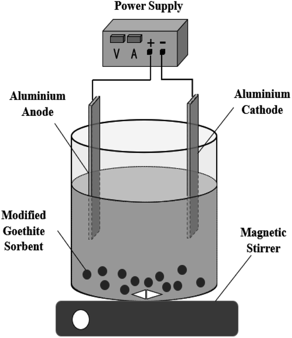
A reactor in which electrocoagulation and adsorption were combined was used to investigate the effect of EC/GMS for treating fluorinated water (Fig. 1). The device consisted of a plastic measuring cup with an effective volume of 1000 mL and a clear water tank. In the reaction cell, two Al electrodes were used as the anode and cathode, separated by a distance of 1 cm, and the adsorbent was placed at the bottom. In the experiment, the anode and cathode were connected to a DC power supply model (MS-155D). Sodium fluoride and deionised water were used to prepare fluorinated water (300 mL) for treatment, while NaCl was used as the electrolyte in the reaction cell for the removal of fluoride. The experiments were performed at room temperature.
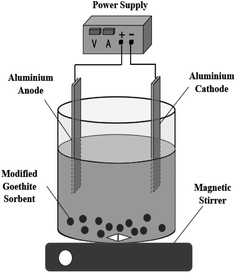 |
| | Fig. 1 Experimental device. | |
2.4 Characterization method
Scanning electron microscopy (SEM) and energy dispersive X-ray spectroscopy (EDX) (FEI Quanta 650, FEI Company, U. S. A.) were used to analyse the surface morphology and elemental compositions of the particles before and after sintering. X-ray diffraction (XRD) (Ultima-IV, Rigaku, Japan), the Brunauer–Emmett–Teller (BET) method (Micromeritics Instrument Ltd, Corp., USA) and Fourier-transform infrared spectroscopy (FT-IR) (Thermo Fisher, USA) were used to record the crystalline texture, specific surface area, and surface properties of GMS. X-ray photoelectron spectroscopy (XPS) (Thermo Scientific Escalab250Xi) and Fourier-transform infrared spectroscopy (FT-IR) (Thermo Fisher, USA) were used to analyse the elements, valence states, and other properties on the surface of the EC-flocs, EC/GMS-flocs, electrodes, and adsorbent after the reaction.
2.5 Response Surface Methodology (RSM)
To optimise the combination with the best removal rate, the data processing software, Design-Expert11.0, was used to design the response surface method. The RSM-BBD method was used to evaluate the effects of three factors, namely the electrolysis time, initial pH, and current density on the rate of fluoride removal from fluorinated water. Seventeen experiments were designed, and the central point was repeated five times. Three levels were set: high (–1), medium (0), and low (−1). The encoded variables and the level of response of the surface method were shown in Table S1.† The experimental data were fitted and analysed by using the software.
2.6 Experimental methods
NaCl (1 M) and the electrodes were placed in the configured fluoride-containing solution (300 mL). Samples were taken every 10 min after the power supply was switched on. The reaction was performed in two modes: EC (without adsorbent) and EC/GMS (add adsorbent). The electrolysis time, initial pH (5, 6, 7, 8, and 9, respectively), current density (6, 12, and 24 mA cm−2, respectively), adsorbent dosage (5, 10, and 15 g, respectively), and initial fluoride concentration (5, 10, and 15 mg L−1, respectively) were controlled to evaluate the efficacy of EC and EC/GMS for removing fluoride. A WS100 portable fluoride ion concentration meter was used to measure the concentration of fluoride in the sample. HCl and NaOH (1 mol L−1, respectively) were used to adjust the pH of the solution. The removal rate of fluoride was calculated from eqn (1).| | |
R = (C0 − Ct)/C0 × 100%
| (1) |
where R is the removal rate after the reaction time t (%); C0 and Ct are the initial concentration and concentration of F− after time t (mg L−1), respectively. The energy consumed in the reaction was calculated using eqn (2).| | |
EEC = 1000Pt/(60Vlog(C0/Ct))
| (2) |
where EEC is the electric energy required to remove 1 cubic meter of pollutant (kW h m−3) per unit volume, P is the rated power (kW), V is the volume of the reaction solution (L), and C0 and Ct are the initial concentration and the concentration (mg L−1) at time t, respectively.
To determine the removal mechanism and reaction rate of the pollutant, kinetic analysis was performed with different initial concentrations of fluoride. Based on this analysis, the removal of fluoride followed a pseudo-first-order model, as shown in eqn (3).
where
C0 is the initial concentration of fluoride,
Ct is the concentration at time
t; the rate constant (
k (min
−1)) was obtained from the plot of ln (
C0/
Ct)
vs. t.
3. Results and discussion
3.1 Comparison of EC and EC/GMS for the removal of fluoride
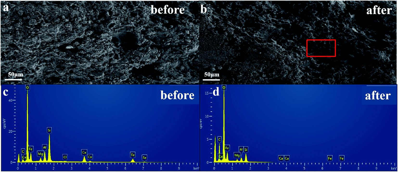
3.1.1 Characterization of the adsorbent. As shown in Fig. 2, SEM and EDX analyses are used to examine the microstructure and elemental composition of GMS before and after modification. Analysis of the surface topography (Fig. 2a and b) reveal that there are many surficial pores on the GMS after firing. Additionally, the surficial roughness of the GMS is relatively high, which suggests that the material provided a large number of adsorption sites. Between 50–500 nm microspheres cover the surface of the GMS after firing. Studies have shown that these microspheres help improve the porosity of the adsorbent, considering that there are more adsorption sites on the surface of the GMS.41 In addition, the EDX results (Fig. 2c and d) show that O, Si, Al, Fe, and other elements are uniformly distributed on the surface of the GMS, which enhance the efficacy of fluoride removal.42 The increased carbon content indicate that parts of the materials are carbonised during firing.
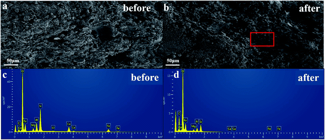 |
| | Fig. 2 SEM (a and b) and EDX (c and d) images of GMS before and after modification. | |
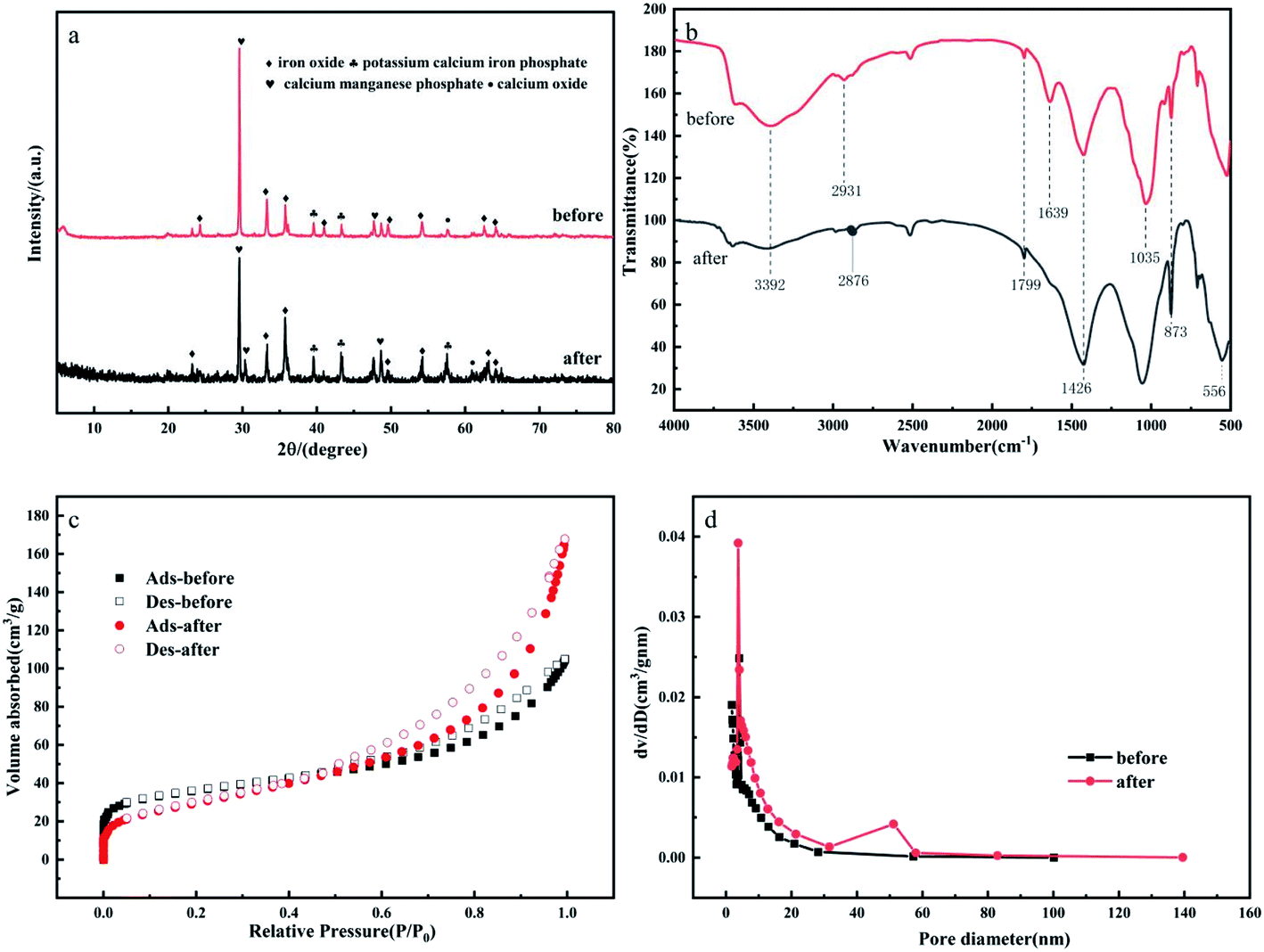
The XRD pattern of GMS in Fig. 3a shows that the main crystalline phases are goethite, montmorillonite and nontronite.43 The characteristic peaks represent iron oxide, potassium calcium iron phosphate, calcium manganese phosphate, and calcium oxide, respectively. The XRD pattern of GMS show low-intensity peaks and broadening of the diffraction peaks after modification. These changes correspond to the small particulate sizes and low crystallinity of the modified goethite. The FT-IR spectra of GMS before and after modification are shown in Fig. 3b. The peak at 3392 cm−1 is related to the hydroxyl group on the surface of the GMS, which become weaker after firing, possibly due to decomposition of water and some hydroxides during the high-temperature calcination. The peaks at 2931 cm−1 and 2876 cm−1, corresponding to the asymmetric stretching vibration of the sp3 hybridised –CH3 and –CH2– groups, indicate that there are few aliphatic hydrocarbons.44 The peaks at 1799 cm−1 and 1639 cm−1 correspond to the stretching vibrations of the C–O and C![[double bond, length as m-dash]](https://www.rsc.org/images/entities/char_e001.gif) O bonds, respectively.45 The peak at 1426 cm−1 corresponds to the bending vibration of the C–H bond in the vinyl group CCH2.46 The peaks at 1035 cm−1 and 873 cm−1 correspond to the symmetric stretching vibrations of the Si–O and Si–O–Si bonds, respectively. The peak at 556 cm−1 corresponds to the vibration of the Fe–O bond (haematite).47 The adsorption of nitrogen and the pore size distribution curve are used to characterise the specific surface areas of GMS before and after modification. Fig. 3c shows that the N2 adsorption–desorption isotherms are type-II, which confirm that GMS is a multilayer adsorbent. The data in Fig. 3d indicate that the sorbent has a mesoporous structure on the nanoscale, where the pore size distribution is centred between 2 and 30 nm. Table 1 shows that the surface area and pore volume of GMS after modification are 128.1656 m2 g−1 and 0.2475 cm3 g−1, respectively, indicating that GMS should provide numerous adsorption sites and should be effective for fluoride adsorption.
O bonds, respectively.45 The peak at 1426 cm−1 corresponds to the bending vibration of the C–H bond in the vinyl group CCH2.46 The peaks at 1035 cm−1 and 873 cm−1 correspond to the symmetric stretching vibrations of the Si–O and Si–O–Si bonds, respectively. The peak at 556 cm−1 corresponds to the vibration of the Fe–O bond (haematite).47 The adsorption of nitrogen and the pore size distribution curve are used to characterise the specific surface areas of GMS before and after modification. Fig. 3c shows that the N2 adsorption–desorption isotherms are type-II, which confirm that GMS is a multilayer adsorbent. The data in Fig. 3d indicate that the sorbent has a mesoporous structure on the nanoscale, where the pore size distribution is centred between 2 and 30 nm. Table 1 shows that the surface area and pore volume of GMS after modification are 128.1656 m2 g−1 and 0.2475 cm3 g−1, respectively, indicating that GMS should provide numerous adsorption sites and should be effective for fluoride adsorption.
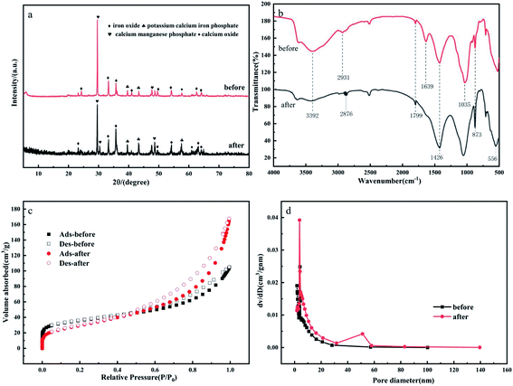 |
| | Fig. 3 (a) XRD patterns, (b) FT-IR spectra, (c) N2 adsorption–desorption isotherms, and (d) pore size distribution of GMS before and after modification. | |
Table 1 BET data
| GMS |
BET surface area (m2 g−1) |
Pore volume (cm3 g−1) |
Average pore diameter (nm) |
| Before modification |
107.4174 |
0.1577 |
7.9557 |
| After modification |
128.1656 |
0.2475 |
6.2204 |
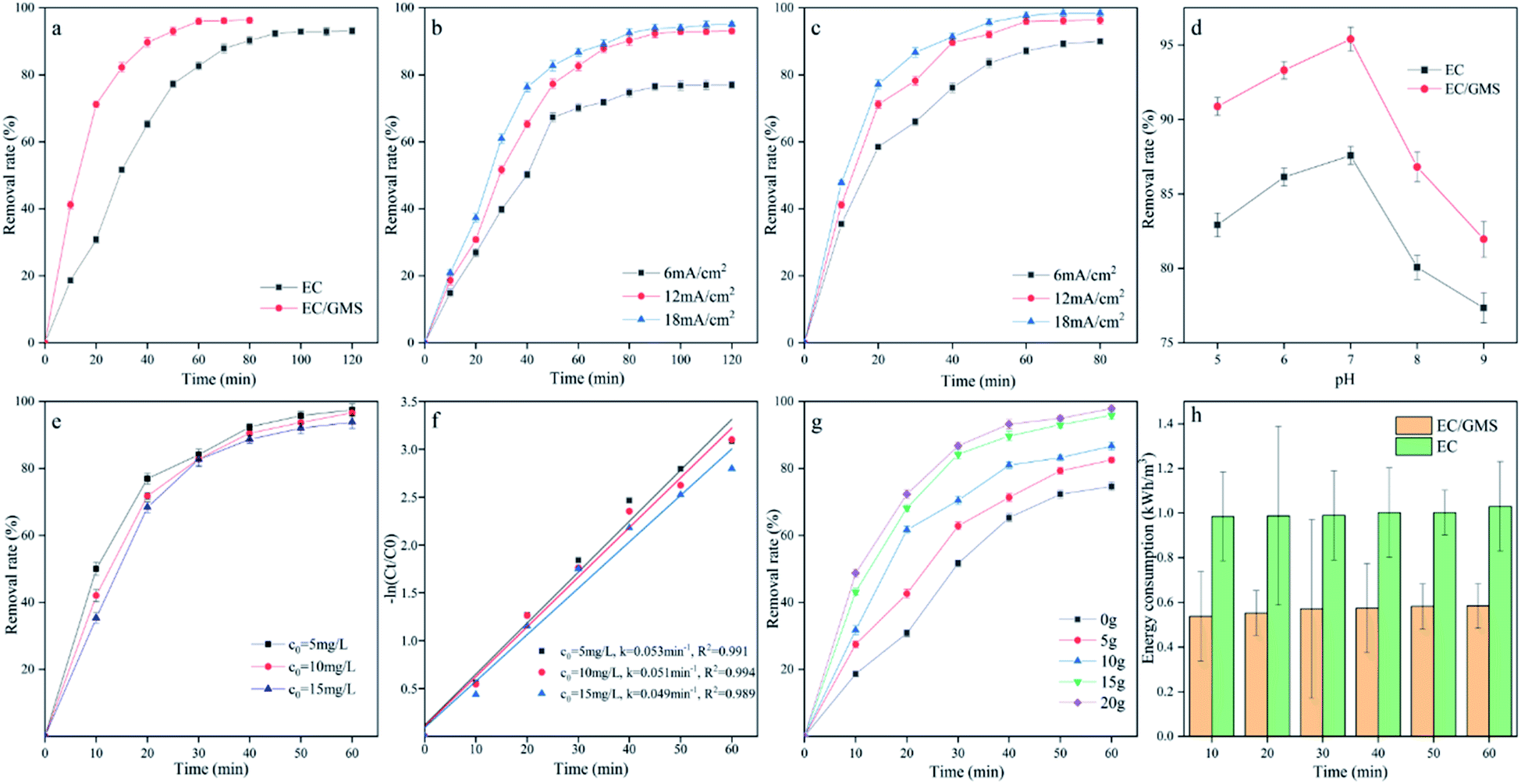
3.1.2 Influence of electrolysis time. The electrolysis time is a crucial factor that can affect the fluoride removal efficiency of the sorbent.48 To prepare the test (simulated) water sample (fluoride concentration of 10 mg L−1), deionised water and a standard solution of fluoride were used. The current density, electrolyte concentration, loading of GMS, and pH were set to 12 mA cm−2, 1 M, 15 g, and 7, respectively. The fluoride removal rate is shown in Fig. 4a. The experimental results show that the removal rate increased as the electrolysis time increased. The fluoride removal rate via electrocoagulation was 93.08% after 120 min. The removal efficiency improved with time because of the significantly higher amounts of aluminium oxides. Furthermore, the coprecipitation of fluoride and aluminium hydroxide formed aluminium fluoride hydroxide complexes [AlnFm(OH)3n−m]49 (eqn (4)). This reaction enhanced the removal of fluoride during adsorption because F− replaced the OH−group in the Aln(OH)3n flocs50–52 (eqn (5)). The addition of GMS during EC also resulted in a faster and higher removal efficiency. A fluoride removal of 96% was achieved after 60 min. The highest fluoride removal and reaction rate were achieved when GMS was added because of the simultaneous use of electrocoagulation and adsorption. So, it seemed that there was an accelerating effect between the electrocoagulation and adsorption process. The adsorption of GMS, chemical adsorption, and coprecipitation between a small amount of ferric hydroxide (eqn (6)) and fluoride, and between aluminium hydroxide and fluoride resulted in the removal of fluoride.53 Defluoridation of the iron flocs was similar to that of the aluminium flocs.| | |
nAl3− − (3n − m)OH− − mF− → AlnFm(OH)3n−m
| (4) |
| | |
Aln(OH)3n − mF− → AlnFm(OH)3n−m − mOH−
| (5) |
| | |
Fe(OH)3 − 3F− → FeF3 − 3OH−
| (6) |
 |
| | Fig. 4 (a) Influence of electrolysis time for EC and EC/GMS; (b) influence of current density for EC; (c) influence of current density for EC/GMS; (d) influence of pH for EC and EC/GMS; (e) influence of initial fluoride concentration of EC/GMS; (g) influence of adsorbent loading on EC and EC/GMS; (f) kinetic analysis at different concentrations; and (h) comparison of energy consumption of EC and EC/GMS. | |
3.1.3 Influence of current density. The formation and evolution of flocs are directly related to the current density applied to the reactor. According to Faraday's law, increasing the current between the electrodes will result in greater coagulation. Several tests were performed at different current densities of 6, 12, and 18 mA cm−2 to study the effect of the current density on the fluoride removal efficiency.25 To perform these tests, the loading of GMS, the electrolyte concentration, pH, and fluoride concentration were set to 15 g, 1 M, 7, and 10 mg L−1, respectively. Fig. 4b and c shows that the fluoride removal rate stabilized at 60 min and 110 min during EC and EC/GMS, respectively. Notably, the removal rate increased faster during EC/GMS. The percentage of fluoride that was removed increased to more than 90% and 95% for both processes when the applied current density was 12 mA cm−2, which allowed the final fluoride concentration to meet the standards of drinking water. Considering the operating costs, 12 mA cm−2 was chosen as the optimal condition for the removal of fluoride.
3.1.4 Influence of initial pH. The pH of the solution is a significant factor during electrocoagulation, which affects the efficiency of fluoride removal. The pH affects the formation of Al(OH)3 flocs because aluminium hydroxide is amphoteric. In the pH range of 5–9,53 positively charged aluminium hydroxide species such as Al(OH)2−, Al(OH)2−, and Al2(OH)24− are formed, which have a large capacity for adsorption and net catching reactions.48 However, at pH > 10, the predominant species is Al(OH)4−, which has a low adsorption capacity. At low pH, the main species is Al3−, which cannot effect coagulation, whereas at pH 6–7, solid Al(OH)3 is the most prevalent.54 Therefore, the pH of the electrolyte can affect the removal efficiency. Consequently, experiments were performed to determine the most favourable initial pH for the removal of fluoride. For these experiments, the current density, electrolyte concentration, adsorbent dosage, and fluoride concentration were set at 12 mA cm−2, 1 M, 15 g, and 10 mg L−1, respectively. The effect of the initial pH on the removal efficiency is shown in Fig. 4d. The variation of the removal rate was similar for EC and EC/GMS; when the initial pH increased from 5 to 9, the fluoride removal efficiency first increased and then decreased. The highest removal rate was achieved at an initial pH of 7. Fig. 4d shows that at pH 7, the removal rates after a treatment period of 60 min were close to 95.39% and 87.69% for EC and EC/GMS, respectively. This result is consistent with the conclusion of previous studies.14,55 The results indicate that as the pH changed, the speciation of aluminium changed to remove fluoride from water. Zhao et al.56 used electrospray ionisation (ESI) mass spectrometry to understand the effect of pH on the formation and decomposition of polymeric aluminium species. They found that at pH 6.4, the amorphous flocs of Al(OH)3 were the final product of the polymerisation and decomposition. In the pH range of 6–7, fluoride was mainly removed by electrostatic attraction and coprecipitation.57 Thus, the subsequent experiments were conducted in the pH range of 6–7.
3.1.5 Influence of initial fluoride concentration. Fig. 4e shows the change in the fluoride concentration during EC/GMS when the current density, electrolyte concentration, adsorbent dosage, and pH were set at 12 mA cm−2, 1 M, 15 g, and 7, respectively. As shown in Fig. 4e, the fluoride removal efficiency was 97.49, 96.63, and 93.88% when the initial fluoride concentration was 5, 10, and 15 mg L−1, respectively.52,58 This trend, which is similar to that obtained by Zhu et al.,52 demonstrates that as the concentration increased, the removal rate gradually decreased. Additionally, EC/GMS was also highly suitable for treating water with a high concentration of fluoride, where the final fluoride concentration met the standard for drinking water. Furthermore, Fig. 4f shows that the primary reaction kinetics constant was 0.053, 0.051, and 0.049 min−1 when the initial fluoride concentration was 5, 10, and 15 mg L−1, respectively. The primary reaction kinetics constant for the removal of fluoride became smaller as the initial fluoride concentration increased, which means that a higher concentration could reduce the reaction rate. Owing to the increased fluoride concentration, the solution required sufficient aluminium ions to remove fluoride. As time progressed, more amorphous aluminium hydroxide precipitated as the addition of aluminium cations increased, which promoted aggregation of the pollutant. Therefore, with sufficient time, higher fluoride removal efficiency was achieved for the remediation of water containing fluoride at high concentrations.
3.1.6 Influence of adsorbent dosage. Fig. 4g compares the evolution of the fluoride removal efficiency using simple EC and EC/GMS with different loadings of GMS (5–20 g) over 60 min.59 Compared to simple EC, the addition of 5 g of GMS to the electrocoagulation cell slightly increased the removal of fluoride. This slight increase is attributed to insufficient addition of GMS to the solution. As the loading increased, the removal rate also increased. When 15 g of GMS was added, the removal of fluoride increased by more than 96% after an electrolysis time 60 min, when compared to a removal rate of 74% for simple EC. An increase in the available adsorption surface area and sites after GMS was added likely explains this result. A further increase in the GMS loading beyond 15 g did not more further increase the removal rate because almost all the ions were either bound to GMS or to the aluminium/iron flocs, which established equilibrium between the ions. A dosage of 15 g was optimal, considering the cost.
3.1.7 Energy consumption of EC and EC/GMS. To further verify the energy consumption of EC and EC/GMS, the energy consumption of both processes was calculated. In order to calculate the energy consumption at different time, the corresponding current density and voltage are recorded every ten minutes, and the recorded value is substituted into the eqn (2) to obtain the energy consumption. Fig. 4h shows the change in the energy consumption with the electrolysis time. When GMS was added, the energy consumption was reduced, which increased the pH of the solution.59 After 1 h of wastewater treatment, the fluoride removal rate and the energy consumption were 95.98% and 0.58 kW h m−3 for EC/GMS, and 82.65% and 1.03 kW h m−3 for EC, respectively. Considering economic factors, such as the reaction time and removal efficiency, EC/GMS was more suitable than EC. EC/GMS required a shorter reaction time and achieved a higher removal efficiency when compared to EC.
3.2 RSM for optimization of the key parameters
To further explore the interaction of various factors and develop an optimal combination scheme, the Box–Behnken design (BBD) was used to evaluate the correlation between different factors and the removal of aqueous fluoride during EC/GMS; to implement the BBD, the results of the single factor test were used. The data processing software, Design-Expert 11.0, was used to design the response surface method. In this method, the removal rate of fluoride was the response variable, while time, current density, and initial pH were the three independent operating factors (Table S1†). The test scheme and results are listed in Table S2.†
Based on the BBD, the removal of fluoride ranged from 57.5 to 97.42% for the experimental combination. A regression model equation (eqn (7)) was used to fit the experimental data, and was used to analyse and predict the optimal level for improving the removal rate.
| | |
Y = 95.51 − 12.39A − 5.48B − 5.57C − 1.94AB − 0.087AC − 0.48BC − 9.73A2 − 4.42B2 − 10.48C2
| (7) |
The variance (ANOVA) of the quadratic response surface model is shown in Table S3.† In this model, the value of P < 0.0001 indicates that the obtained level was extremely significant, while the missing term, P = 0.5249 > 0.05, was not significant, which indicates that the simulation was good.60 The adjusted regression coefficient (R2adj = 0.9947) was close to R2, which indicates that the model explained 99.47% of the change in the response values. The fit of the equation was good and could be used to optimise the analysis and predict the test results. The F-value revealed that the influence of the three operational factors on the removal rate of fluoride decreased in the order, time > initial pH > current density.61
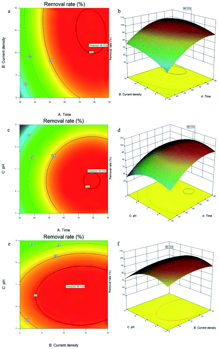
The response surface diagram shows the optimal level of a single operating parameter, which was derived from the interaction between two independent factors (Fig. 5a–f). Elliptical shapes were generated due to perfect interactions between the optimal predicted values and various parameters.62 Fig. 5a and b show the effects of the time and current density on the removal of fluoride. The removal rate increased and then stabilised, but the surface had a greater degree of curvature for time than for the current density, which indicates that time had a greater impact on the removal rate than the current density. Comparatively, the contour maps of these variables became elliptical, which indicates that the interaction of these variables influenced the removal rate.63 The effect of the time and initial pH on the removal is shown in Fig. 5c and d. The relatively flat surfaces indicate that both of these variables largely influenced the removal rate. The variation of the removal rate was similar to that in the single-factor experiment. The contour maps confirmed that the interaction of these variables influenced the removal rate. Fig. 5e and f shows that the initial pH and current density first increased the removal rate, which then decreased as the initial pH and current density increased. The contour maps similarly confirmed that the interaction of these variables influenced the removal rate. All the plots showed an optimal removal rate of 99.1334%.
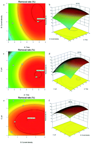 |
| | Fig. 5 Contour and surface plots showing the relationship between the removal of fluoride (%) and independent parameters: (a and b) time–current density, (c and d) time–initial pH, and (e and f) initial pH–current density. | |
The BBD was used to predict the optimal experimental conditions for the removal of fluoride using EC/GMS. These optimal experimental conditions (79.919 min, 6.724, and 11.303 mA cm−2) afforded a removal efficiency of 99.47%. To check the accuracy of the BBD, three groups of parallel experiments were conducted to predict the optimal conditions. The average percentage of fluoride removed was 98.19%, which differed from the predicted value by 1.28%. Therefore, the RSM-BBD model showed good predictive power, which indicates that it was useful for optimising the parameters.
3.3 Analysis of mechanism and reusability of method
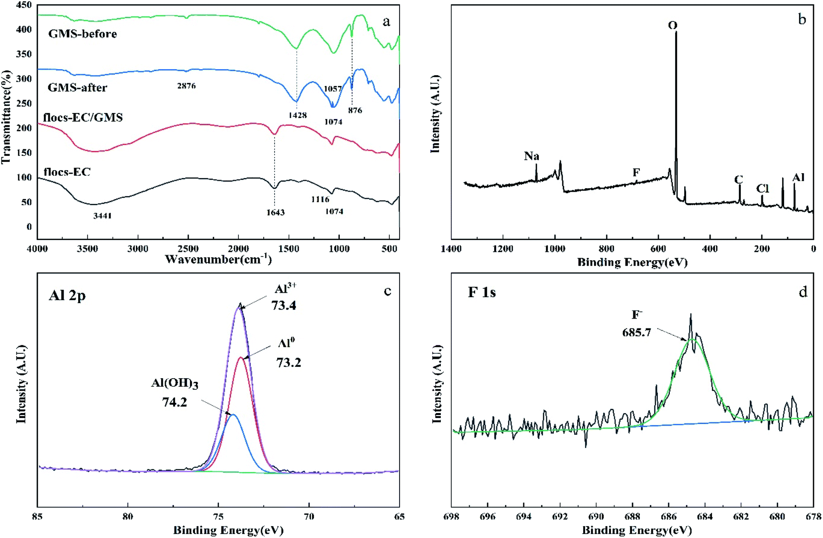
3.3.1 FT-IR and XPS analysis of the flocs, GMS, and electrodes. To determine the functional groups responsible for the adsorption of fluoride, FT-IR analysis in the range 400–4000 cm−1 was performed on the GMS, EC, and EC/GMS flocs. The results are shown in Fig. 6a. The characteristic peaks of GMS before and after reaction were observed at 1428 cm−1, 1057 cm−1, and 876 cm−1, associated with the vibration of the C–O bond of the carbonate (CO3) groups. Ion exchange and electrostatic interactions were two processes for fluoride removal; these processes occurred when GMS dissolved the carbonate, resulting in its release.64,65 The disappearance of the C–H peak at 2876 cm−1 indicates that the C–H bonds were broken and GMS was involved in the reaction. The peak at 1074 cm−1 correspond to the stretching vibration of the C–F bond which proved the adsorption of F− by GMS. The spectra of EC and EC/GMS were similar. However, the spectrum of EC exhibited a lower intensity. Broad peaks were observed at 3441 cm−1 and 1116 cm−1, corresponding to the stretching vibrations of O–H and M–OH (where M is the metal).59 The peaks at 1643 cm−1 and 1074 cm−1 correspond to the stretching vibrations of the CO and C–F bonds, respectively. These spectra showed that the hydroxyl group is the main functional group responsible for the removal of fluoride and the existence of fluoride on the flocs.
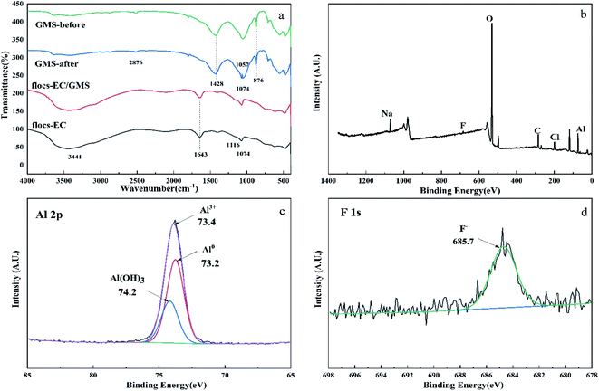 |
| | Fig. 6 (a) FT-IR spectra of the EC flocs, EC/GMS flocs, and GMS before and after reaction, (b) XPS survey scan of flocs after EC/GMS process, (c) Al 2p spectrum of flocs after EC/GMS process, and (d) F 1s spectrum of flocs after EC/GMS process. | |
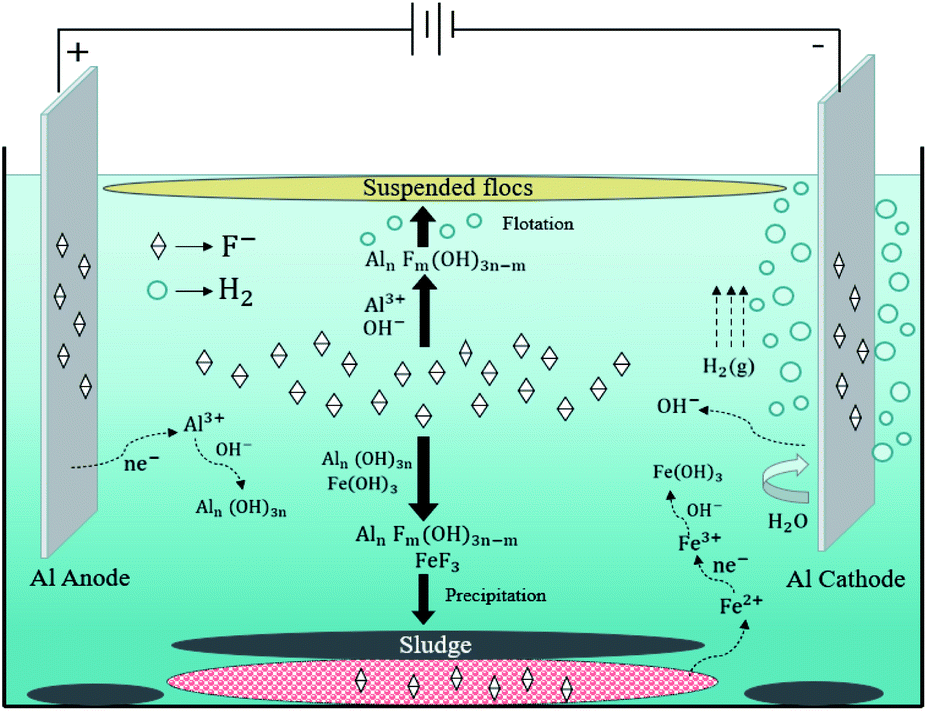
XPS was used to identify the elemental composition of the surface of the flocs after EC/GMS process (Fig. 6b–d). In addition to the C 1s, O 1s, Na 1s, Cl 2p, and Al 2p peaks of the solution, the full-spectrum scan of the flocs showed an obvious F 1s peak around 680 eV, indicating the removal of F− (Fig. 6b).66 The Al 2p XPS profile of the flocs displayed three characteristic peaks at 73.2, 73.4, and 74.2 eV, which indicated the presence of Al, Al3–, and Al(OH)3, respectively67 (Fig. 6c). Specifically, the presence of Al3– and Al(OH)3 suggests that the removal of fluoride depended on chemical adsorption and co-precipitation. The peak at 685.7 eV showed that ionic fluoride was the only fluoride species that was removed68 (Fig. 6d). The flocs were removed when F− replaced the OH− group of [Aln(OH)3n]. Additionally, the fluoride and hydroxide ions co-precipitated with Al3– ions to form [AlnFm(OH)3n−m]. XPS was used to analyse the Al electrodes and GMS after defluoridation. The results of this analysis proved that ionic fluoride existed on the surficial layers (Table 2). The results also demonstrate that electrophoresis of the electrodes and adsorption of the GMS remove fluoride.52 The FT-IR and XPS results proved some of these fluoride removal pathways as shown in figure: (i) chemical adsorption and co-precipitation with other ions; (ii) adsorption of GMS; (iii) electrophoresis of the electrodes. Combined with the previous experimental results that obtained from the influence of electrolysis time and mechanism analysis, it is believed that the addition of electrophoresis, adsorption and other processes may accelerate the electrocoagulation process (Fig. 7).
Table 2 XPS analysis of the surface of the electrodes and GMS
| Atomic concentration (%) |
Cl 2p |
F 1s |
Fe 2p |
Na 1s |
Al 2p |
C 1s |
| Anode |
3.62 |
1.58 |
0.80 |
2.88 |
52.57 |
38.56 |
| Cathode |
2.77 |
0.80 |
1.11 |
1.45 |
50.91 |
42.96 |
| GMS |
2.54 |
3.05 |
8.42 |
1.80 |
25.75 |
58.43 |
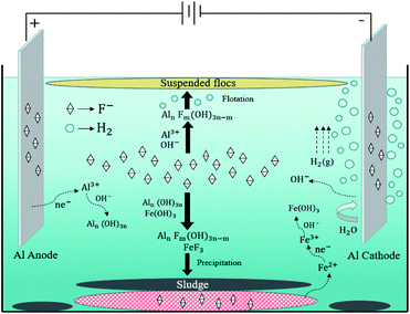 |
| | Fig. 7 Schematic illustration of the fluoride removal mechanism by EC/GMS. | |
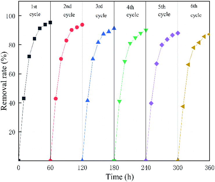
3.3.2 Reusability of EC/GMS. To explore the reusability of EC/GMS in fluoride removal, the experiment was repeated six times under the optimal combination of conditions (electrolysis time = 80 min, initial pH = 6.724, current density = 11.303 mA cm−2, initial fluoride concentration = 5 mg L−1, and adsorbent dosage = 15 g). As shown in Fig. 8, the removal rate remained above 87% after six cycles, which was higher than that of the simple EC. This result indicates that the reusability of the sorbent is good. The mechanical test revealed that the hardness of GMS decreased with numerous repetitions, which affected the determination of the fluoride concentration.
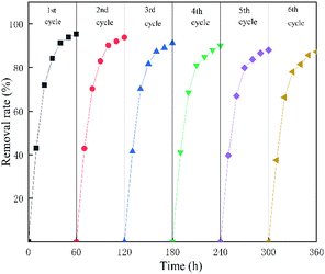 |
| | Fig. 8 Reusability of EC/GMS for the removal of fluoride. | |
4. Conclusions and perspectives
EC/GMS, a coupled method, was developed and used for the removal of fluoride from water. SEM-EDX, FT-IR, BET, and XRD analyses confirmed that modified GMS had good fluoride adsorption and removal properties. The addition of GMS can reduce costs when compared to the simple EC, which requires more energy consumption and a longer electrolysis time. EC/GMS could achieve a faster removal efficiency when compared to EC at the same electrolysis time, pH, and current density. Single-factor experiments and RSM-BBD optimization experiments revealed that EC/GMS achieved a removal efficiency of 99.47%. Evaluation of the reaction kinetics with different fluoride concentrations showed that the removal rate of the device was quick for solutions that contained a high and low concentration of fluoride. The electrodes, GMS, and flocs were also characterised. Electrophoresis of the electrodes, adsorption of GMS, and co-precipitation of flocs were the main processes by which fluoride was removed. The reuse performance of this method was also good.
Nowadays, one of the most significant challenges is to develop adequate technologies for fluoride treatment. Therefore, it is essential to guarantee an appropriate operation with high volume and flow rate for aqueous solutions to expand the EC/GMS technology for the welfare of humans and the environment.
Author contributions
J. L. Kang: conceptualization, methodology, software, data curation, writing–original draft preparation; T. T. Gu, C. X. Ma, J. K. Wang and S. L. Liu: visualization, investigation; J. F. Li: supervision, involved in conceptualization, methodology, software and english revising; L. J. Yi: involved in software and validation.
Conflicts of interest
The authors declare that they have no conflicts of interest.
Acknowledgements
Financial support from the National Natural Science Foundation of China (22109106, 42107414) and the Key Production Innovative Development Plan of the Southern Bingtuan (2019DB007, 2020AB024) are gratefully acknowledged.
References
- K. K. Yadav, N. Gupta, V. Kumar, S. A. Khan and A. Kumar, Environ. Int., 2018, 111, 80–108 CrossRef CAS PubMed.
- Meenakshi and R. C. Maheshwari, J. Hazard. Mater., 2006, 137, 456–463 CrossRef CAS PubMed.
- G. Biswas, M. Kumari, K. Adhikari and S. Dutta, Curr. Pollut. Rep., 2017, 3, 104–119 CrossRef CAS.
- A. M. Gbadebo, Environ. Geochem. Health, 2012, 34, 597–604 CrossRef CAS PubMed.
- U. S. Rashid and A. N. Bezbaruah, Chemosphere, 2020, 252, 126639 CrossRef CAS PubMed.
- M. Amini, K. Mueller, K. C. Abbaspour, T. Rosenberg, M. Afyuni, K. N. Moller, M. Sarr and C. A. Johnson, Environ. Sci. Technol., 2008, 42, 3662–3668 CrossRef CAS PubMed.
- N. Mumtaz, G. Pandey and P. K. Labhasetwar, Crit. Rev. Environ. Sci. Technol., 2015, 45, 2357–2389 CrossRef CAS.
- V. N. Karbasdehi, S. Dobaradaran, A. Esmaili, R. Mirahmadi, F. F. Ghasemi and M. Keshtkar, Data Brief, 2016, 8, 867–870 CrossRef PubMed.
- K. Bani-Melhem and R. Elektorowicz, Environ. Sci. Technol., 2010, 44, 3298–3304 CrossRef CAS PubMed.
- W.-F. Ma and W.-J. Liu, Huanjing Kexue, 2009, 30, 787–791 CAS.
- M. Tahaikt, R. El Habbania, A. A. Haddou, I. Acharya, Z. Amora, M. Takya, A. Alamil, A. Boughriba, A. Hafsil and A. Elmidaoui, Desalination, 2007, 212, 46–53 CrossRef CAS.
- M. Valentukeviciene, R. Zurauskiene and Y. A. Boussouga, Ecol. Chem. Eng. S, 2019, 26, 133–147 CAS.
- R. P. Liu, B. Liu, L. J. Zhu, Z. He, J. W. Ju, H. C. Lan and H. J. Liu, J. Environ. Sci., 2015, 32, 118–125 CrossRef CAS PubMed.
- W.-X. Gong, J.-H. Qu, R.-P. Liu and H.-C. Lan, Colloids Surf., A, 2012, 395, 88–93 CrossRef CAS.
- Y. Ye, Y. Wei, Y. Gu, D. Kang, W. Jiang and J. Kang, J. Alloys Compd., 2020, 838, 155528 CrossRef CAS.
- B. Palahouane, A. Keffous, M. W. Naceur, M. Hecini, O. Bouchelaghem, A. Lami, K. Laib, A. Manseri and N. Drouiche, Desalin. Water Treat., 2020, 183, 240–247 CrossRef CAS.
- L. F. Castaneda, O. Coreno, J. L. Nava and G. Carreno, Chemosphere, 2020, 244, 125417 CrossRef CAS PubMed.
- Z. He, R. Liu, J. Xu, H. Liu and J. Qu, Sep. Purif. Technol., 2015, 148, 68–75 CrossRef CAS.
- F. Zhu, Z. Guo and X. Hu, J. Hazard. Mater., 2020, 397, 122789 CrossRef CAS PubMed.
- T. Tanigami, H. Iwata and T. Mori, J. Appl. Polym. Sci., 2007, 103, 2788–2796 CrossRef CAS.
- R. J. Won and C. O. Park, Membr. J., 2017, 27, 84–91 CrossRef.
- D. Das and B. K. Nandi, J. Environ. Chem. Eng., 2020, 8, 103643 CrossRef CAS.
- M. Lopez-Guzman, M. T. Alarcon-Herrera, J. R. Irigoyen-Campuzano, L. A. Torres-Castanon and L. Reynoso-Cuevas, Sci. Total Environ., 2019, 678, 181–187 CrossRef CAS PubMed.
- V. F. Mena, A. Betancor-Abreu, S. Gonzalez, S. Delgado, R. M. Souto and J. J. Santana, J. Environ. Manage., 2019, 246, 472–483 CrossRef CAS PubMed.
- M. Alimohammadi, A. Mesdaghinia, M. H. Shayesteh, H. J. Mansoorian and N. Khanjani, Int. J. Environ. Sci. Technol., 2019, 16, 8239–8254 CrossRef CAS.
- J. F. A. Silva, N. S. Graça, A. M. Ribeiro and A. E. Rodrigues, Sep. Purif. Technol., 2018, 197, 237–243 CrossRef CAS.
- V. L. Dhadge, C. R. Medhi, M. Changmai and M. K. Purkait, Chemosphere, 2018, 199, 728–736 CrossRef CAS PubMed.
- B. K. Nandi and S. Patel, Arabian J. Chem., 2017, 10, S2961–S2968 CrossRef CAS.
- K. S. Hashim, A. Shaw, R. Al Khaddar, M. O. Pedrola and D. Phipps, J. Environ. Manage., 2017, 189, 98–108 CrossRef CAS PubMed.
- S. V. Jadhav, E. Bringas, G. D. Yadav, V. K. Rathod, I. Ortiz and K. V. Marathe, J. Environ. Manage., 2015, 162, 306–325 CrossRef CAS PubMed.
- W. Zuo, G. Zhang, M. Qin and H. Zhang, Pollut. Control Technol., 2004, 222, 187–196 Search PubMed.
- M. Kim, C. E. Choong, S. Hyun, C. M. Park and G. Lee, Chemosphere, 2020, 253, 126580 CrossRef CAS PubMed.
- S. Huang, M. Hu, D. Li, L. Wang, C. Zhang, K. Li and Q. He, Fuel, 2020, 279, 118486 CrossRef CAS.
- W. Li, T. Zhang, L. Lv, Y. Chen, W. Tang and S. Tang, Colloids Surf., A, 2021, 624, 126791 CrossRef CAS.
- N. V. Narayanan and M. Ganesan, J. Hazard. Mater., 2009, 161, 575–580 CrossRef CAS PubMed.
- M. Malakootian, H. J. Mansoorian and M. Moosazadeh, Desalination, 2010, 255, 67–71 CrossRef CAS.
- T. Wang, L. Y. Zhang, H. Y. Wang, W. C. Yang, Y. C. Fu, W. L. Zhou, W. T. Yu, K. S. Xiang, Z. Su, S. Dai and L. Y. Chai, ACS Appl. Mater. Interfaces, 2013, 5, 12449–12459 CrossRef CAS PubMed.
- M. G. Goren, R. M. Bolanz, S. Parry, J. Goettlicher, R. Steininger and J. Majzlan, Clays Clay Miner., 2021, 69, 188–204 CrossRef.
- D. Bhatt, N. Gururani, A. Srivastava and P. C. Srivastava, Environ. Earth Sci., 2021, 80, 273 CrossRef CAS.
- T. L. Wu, Q. Sun, G. D. Fang, P. X. Cui, C. Liu, M. E. Alves, W. X. Qin, D. M. Zhou, Z. Q. Shi and Y. J. Wang, Chem. Eng. J., 2019, 369, 414–421 CrossRef CAS.
- Y. Wen, Y. Ji, S. Zhang, J. Zhang and G. Cai, Polymers, 2019, 11, 711 CrossRef CAS PubMed.
- X. Teng, J. Li, J. Wang, J. Liu, X. Ge and T. Gu, Sep. Purif. Technol., 2021, 267, 118661 CrossRef CAS.
- V. P. Ponomar, Miner. Eng., 2018, 127, 143–152 CrossRef CAS.
- J. Xu, L. K. Koopal, M. Wang, J. Xiong, J. Hou, Y. Li and W. Tan, Environ. Sci.: Nano, 2019, 6, 3625–3637 RSC.
- Y.-y. Ma, F.-y. Ma, W.-l. Mo and Q. Wang, Fuel, 2020, 266, 117039 CrossRef CAS.
- S. Salustro, A. M. Ferrari, F. S. Gentile, J. K. Desmarais, M. Rerat and R. Dovesi, J. Phys. Chem. A, 2018, 122, 594–600 CrossRef CAS PubMed.
- B. B. Zviagina, V. A. Drits and O. V. Dorzhieva, Minerals, 2020, 10, 153 CrossRef CAS.
- U. T. Un, A. S. Koparal and U. B. Ogutveren, Chem. Eng. J., 2013, 223, 110–115 CrossRef.
- M. M. Emamjomeh and M. Sivakumar, J. Environ. Manage., 2009, 90, 1204–1212 CrossRef CAS PubMed.
- M. Bennajah, B. Gourich, A. H. Essadki, C. Vial and H. Delmas, Chem. Eng. J., 2009, 148, 122–131 CrossRef CAS.
- C. Y. Hu, S. L. Lo, W. H. Kuan and Y. D. Lee, Water Res., 2005, 39, 895–901 CrossRef CAS PubMed.
- J. Zhu, H. Zhao and J. Ni, Sep. Purif. Technol., 2007, 56, 184–191 CrossRef CAS.
- U. T. Un, A. S. Koparal, U. B. Ogutveren and A. Durucan, Fresenius Environ. Bull., 2010, 19, 1906–1910 CAS.
- U. T. Un, A. S. Koparal and U. B. Ogutveren, J. Environ. Manage., 2009, 90, 428–433 CrossRef CAS PubMed.
- S. Vasudevan, S. K. Balasingam, J. Lakshmi, S. Mohanraj and G. Sozhan, J. Chem. Technol. Biotechnol., 2011, 86, 428–436 CrossRef CAS.
- H. Zhao, H. Liu and J. Qu, J. Colloid Interface Sci., 2009, 330, 105–112 CrossRef CAS PubMed.
- R. Zhou, F. Liu, N. Wei, C. Yang, J. Yang, Y. Wu, Y. Li, K. Xu, X. Chen and C. Zhang, J. Water Proc. Eng., 2020, 37, 101387 CrossRef.
- D. Ghosh, C. R. Medhi and M. K. Purkait, Chemosphere, 2008, 73, 1393–1400 CrossRef CAS PubMed.
- S. Elabbas, N. Adjeroud, L. Mandi, F. Berrekhis, M. N. Pons, J. P. Leclerc and N. Ouazzani, Int. J. Environ. Anal. Chem., 2020, 1761963 Search PubMed.
- G. I. Danmaliki, T. A. Saleh and A. A. Shamsuddeen, Chem. Eng. J., 2017, 313, 993–1003 CrossRef CAS.
- J. Yang, C. Ma, J. Tao, J. Li, K. Du, Z. Wei, C. Chen, Z. Wang, C. Zhao and M. Ma, Carbohydr. Polym., 2020, 245, 116542 CrossRef CAS PubMed.
- M. Zhu, X. Yin, Q. Liu and Z. Feng, Pol. J. Environ. Stud., 2020, 29, 2493–2502 CrossRef CAS.
- A. Witek-Krowiak, K. Chojnacka, D. Podstawczyk, A. Dawiec and K. Pokomeda, Bioresour. Technol., 2014, 160, 150–160 CrossRef CAS PubMed.
- Z. Chen, Y. Liu, L. Mao, L. Gong, W. Sun and L. Feng, Ceram. Int., 2018, 44, 6002–6009 CrossRef CAS.
- J. He, K. Chen, X. Cai, Y. Li, C. Wang, K. Zhang, Z. Jin, F. Meng, X. Wang, L. Kong and J. Liu, J. Colloid Interface Sci., 2017, 490, 97–107 CrossRef CAS PubMed.
- J. T. Feng, Z. Y. Wang, W. L. Zhang, X. Y. Zhao, J. T. Zhang, Y. P. Liu and W. Yan, Environ. Sci. Pollut. Res., 2021, 28, 1–13 CrossRef PubMed.
- Y. Wang, L. Yu, R. Wang, Y. Wang and X. Zhang, J. Colloid Interface Sci., 2020, 564, 392–405 CrossRef CAS PubMed.
- C. J. L. Silwood, I. Abrahams, D. C. Apperley, N. P. Lockyer, E. Lynch, M. Motevalli, R. M. Nix and M. Grootveld, J. Mater. Chem., 2005, 15, 1626–1636 RSC.
Footnote |
| † Electronic supplementary information (ESI) available. See DOI: 10.1039/d1ra08503d |
|
| This journal is © The Royal Society of Chemistry 2022 |
Click here to see how this site uses Cookies. View our privacy policy here. 
 Open Access Article
 This Open Access Article is licensed under a Creative Commons Attribution-Non Commercial 3.0 Unported Licence
 *a,
Chengxiao Maa,
Lijuan Yib,
Tiantian Gub,
Jiankang Wanga and
Shenglin Liuc
*a,
Chengxiao Maa,
Lijuan Yib,
Tiantian Gub,
Jiankang Wanga and
Shenglin Liuc