
 Open Access Article
 This Open Access Article is licensed under a Creative Commons Attribution-Non Commercial 3.0 Unported Licence
Experimental study of the thermal storage and mechanical properties of microencapsulated phase change composites during a supersonic cruise
C. Zhanga,
Y. Wanga,
Z. G. Jinb,
H. B. Kec and
H. Wang *a
*a
aSchool of Aeronautics, Northwestern Polytechnical University, Xi’ an, Shaanxi 710072, China. E-mail: wanghui2018@nwpu.edu.cn
bHaiwing Aerospace Materials Research Institute (Suzhou) Co., Ltd, 215002, China
cScience and Technology on Thermal Energy and Power Laboratory, Wuhan Second Ship Design and Research Institute, Wuhan 430205, China
First published on 21st February 2022
Abstract
Microencapsulated phase change composites, one of the high-efficiency thermal protection media, are widely used in the thermal protection of supersonic aircraft. The phase transition occurring during the cruise of supersonic aircraft leads to a change in the mechanical properties of microencapsulated phase change composites (MPCMs). In this study, we experimentally studied the variations of the mechanical properties of MPCMs during cruise. The effects of the volume fraction ratio of core to shell on the thermal storage and mechanical properties of the microencapsulated phase change composites are investigated. Results show that the latent heat capacity increases with an increase in the volume fraction ratio of core to shell. The deformation mode translates from a brittle fracture into a brittle deformation status during the phase transition. The mechanical properties of the MPCMs decrease at three conditions without phase transition, during phase transition and complete phase transition, respectively, with an increase in the ratio of core to shell as well as increased temperature. The above-mentioned findings can guide the design of a best thermal management system for supersonic aircraft.
1. Introduction
Phase change materials (PCMs) are normally regarded as a good candidate for thermal management. The high abilities of PCMs to release and store energy in the form of latent heat promotes them to be applied in numerous applications, such as thermal protection,1,2 electronic cooling systems,3,4 and energy storage systems.5–7 Microencapsulation is widely adopted to prevent the leak of melted PCMs (also called microencapsulated phase change materials, MPCMs), and control the volume fluctuations when the phase transition occurs.8 Thus, they are widely used for reducing the heat damage to supersonic aircraft.1The latent heat capacity and thermal conductivity properties of MPCMs are mainly considered in literature.9–14 For the latent heat capacity, the methods of controlling the core/coating mass ratio,15 shape of MPCM inclusions,16 and polydopamine-functionalized graphene oxide17 are frequently used to enhance the latent heat capacity of MPCM. For example, Al-Mudhafar et al.18 designed a webbed tube heat exchanger to increase the latent heat thermal energy storage capacity of MPCMs. Besides, as the thermal conductivity of pure PCMs is usually low to impede the heat transfer capacity in the MPCM structure, high thermal conductivity materials, such as metal foam,19 graphite,20 graphene oxide,21 carbon fiber sheet,22 Ag doped ZnO materials, are usually considered to be added into the MPCMs.23 Dong et al.22 found that a 14.4% (in volume) carbon fiber sheet can improve the effective thermal conductivity of the MPCM composite by 24.4 W m−1 K−1. Dinesh et al.24 investigated the effects of the metal foam geometry in the MPCM composite structure on the total energy absorption. They found that the optimum porosity is dependent on the heat transfer duration.
In fact, the MPCMs are often carried out in a phase change condition during cruise for the supersonic aircraft; therefore, the mechanical properties of the MPCMs are influenced by the aerodynamic force, particularly for the function of bearing capacity.25 Djamai et al.26 found that the ductile mechanical behavior of textile reinforced concrete composites is maintained in the presence of microencapsulated PCMs. However, they found that the mechanical performance of the PCM-textile reinforced concrete will decrease with an increase in the PCM rate. Young et al.27 studied the volumetric thermal deformation in the microstructure of MPCMs. Results show that the thermal deformation coefficient of MPCMs exists near the shell material because the capsules are not completely filled with the MPCMs. Gürbüz et al.28 reported that the compressive strength can be lost when the addition phase change materials are significantly compensated. Wei et al.29 carefully studied the effects of the MPCM inclusions, compliant on the cracking resistance of the cementitious composites. However, they found that the additions of MPCMs do not alter the cracking sensitivity of the MPCMs material. As reviewed above, the mechanical properties of the MPCM structure during cruise for the supersonic aircraft have never been investigated, particularly for the three typical conditions, without phase transition, during phase transition and complete phase transition.
In this study, the thermal storage capacity of the MPCMs is examined by differential scanning calorimetry (DSC). Furthermore, the mechanical properties of the MPCM structure during cruise for the supersonic aircraft was experimentally studied. The effects of the volume fraction ratio of core to shell on the mechanical properties of MPCMs are considered in details.
2. Background
In the present study, a simulated reusable condition is applied as the service condition for the MPCM blunt structures. Fig. 1 shows the typical structure of blunt aircraft with the thermal protection structure. The MPCM blunt structure consists of three parts: the ablation resistant layer, regular insulating layer and heat storage layer. The ablation resistant layer usually includes a high-temperature layer made of C/SiC. The insulation layers involve a regular insulating material, and the heat storage layer is MPCMs. As the temperature caused by the aerodynamic heat around the aircraft can reach up to over 1000 °C at stratosphere pressure and the aerodynamic force caused by the compressed air can reach up to about 6 MPa at Ma = 5. The C/SiC layer plays an essential role in directly bearing a high temperature and structural loads, while the insulation layer is responsible for delaying the internal heat transfer. Thus, the temperature reaching up to the bottom of the heat storage layer should not be higher than 100 °C because the electronic devices cannot be subjected to excessive temperatures. In this study, the MPCM structure can afford above conditions. Therefore, during cruise, there will be three typical conditions for the MPCM structure, namely without phase transition, during phase transition and complete phase transition.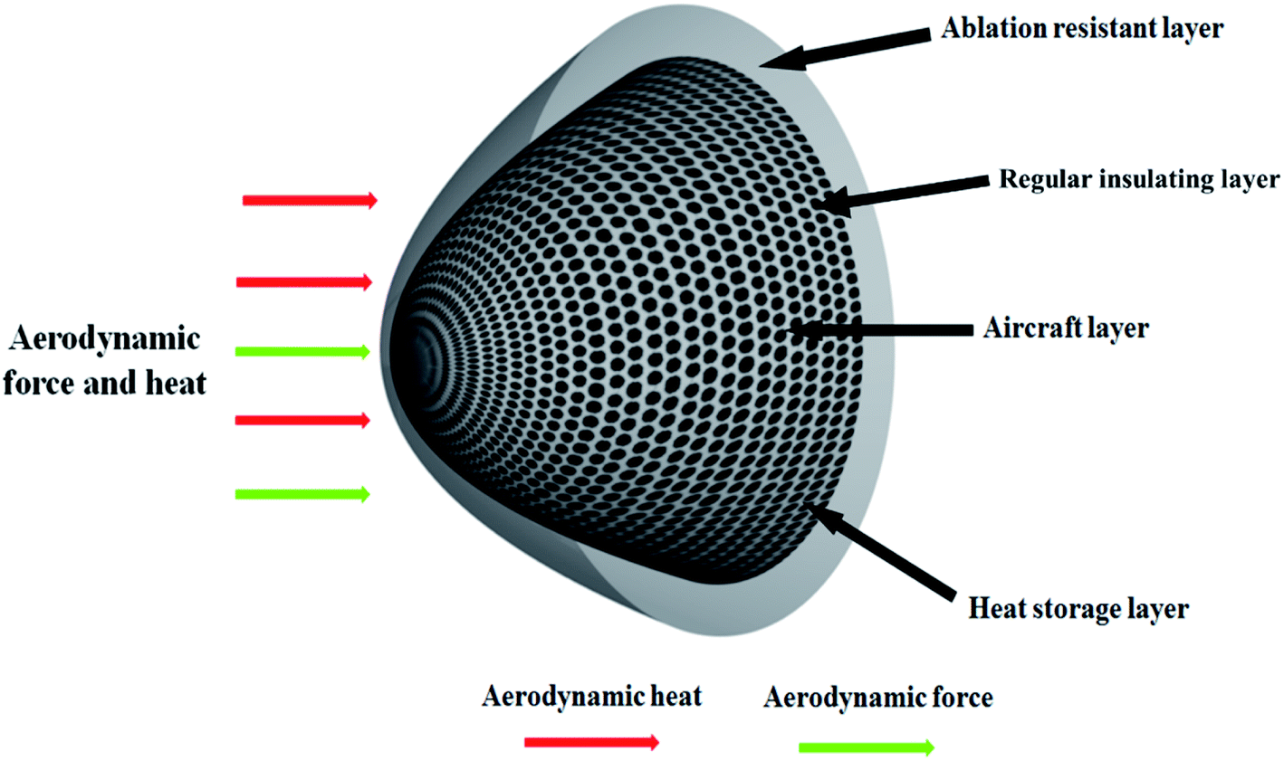 | ||
| Fig. 1 Thermal protection system for the supersonic aircraft during cruise. | ||
3. Experimental program
3.1. Material design
The synthesis process of the microencapsulated phase change composite structure involves three steps, namely mixture, mould pressing, solidification, as displayed in Fig. 2. Fig. 2 shows the detail synthesis process of microencapsulated phase change composites. The paraffin wax is selected as phase change materials. The paraffin is treated as the core, and the melamine-formaldehyde resin is treated as the shell, which is used as thermosetting resin. First, the epoxy resin, curing agent, butanone and phase change microcapsules are mixed several times, and then, the mixture is placed in the fume hood for about 1 h at 20 °C. A viscous mixture can be obtained after the partial volatilization of butanone solvent. Three kinds of phase change microcapsules are synthesized by controlling the volume fraction ratio of core to shell. The volume fraction ratios of core to shell are 70![[thin space (1/6-em)]](https://www.rsc.org/images/entities/char_2009.gif) :30, 90:10 and 96:4 with a constant ratio of epoxy resin and curing agent in all the MPCMs, respectively. This is because that above three cases widely exist in the practical application and the production process is more mature. In future, different volume fraction ratios can be chosen to synthesize. They are also named as Case 1(C1), Case 2(C2), Case 3(C3), respectively. Second, the mixture is put in the mold. Then, it is compacted after the mold is closed, while pressure is set at about 13–14 MPa with 2 min. Later, the screw is locked in the mold. Third, the mold is placed in an oven at 50 ± 5 °C for 72 h to remove the butanone. Then, after the temperature is dropped to 20 °C, the mold is removed. The microencapsulated phase change composites are obtained, as shown in Fig. 2.
:30, 90:10 and 96:4 with a constant ratio of epoxy resin and curing agent in all the MPCMs, respectively. This is because that above three cases widely exist in the practical application and the production process is more mature. In future, different volume fraction ratios can be chosen to synthesize. They are also named as Case 1(C1), Case 2(C2), Case 3(C3), respectively. Second, the mixture is put in the mold. Then, it is compacted after the mold is closed, while pressure is set at about 13–14 MPa with 2 min. Later, the screw is locked in the mold. Third, the mold is placed in an oven at 50 ± 5 °C for 72 h to remove the butanone. Then, after the temperature is dropped to 20 °C, the mold is removed. The microencapsulated phase change composites are obtained, as shown in Fig. 2.
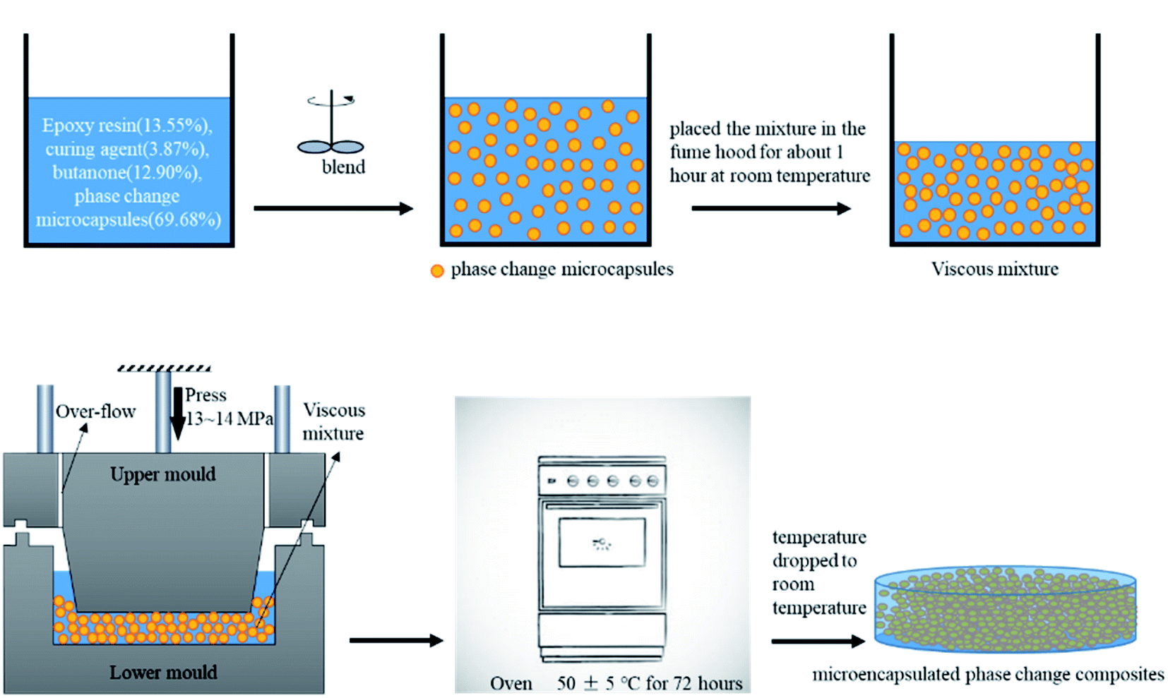 | ||
| Fig. 2 Flow chart for the preparation of microencapsulated phase change composites. | ||
3.2. Characterization measurement
DSC test was carried out to obtain the thermal properties of the MPCMs. The sample mass is about 5 g. The latent heat of MPCMs during the melting and solidification is obtained on a data acquisition instrument in DSC equipment. The DSC curve is measured by NETZSCH DSC 214 (Analytical & Testing Center of Northwestern Polytechnical University). The experimental temperature ranges from 10 °C to 150 °C, and the heating rate is 2 °C min−1.3.3. Mechanical property test
The loading states for the MPCM structure were determined, as shown in Fig. 3. The test piece of microencapsulated phase change composites is a cube with a size of 20 × 20 × 20 mm3. Uniaxial compression experiments are conducted by using an electronic universal tester (DDL100, Changchun Institute of Mechanical Science Co., Ltd). In the test process, the values of time, displacement, and load are recorded at a frequency of 10 Hz. The experiments are performed at a constant strain rate of 1 × 10⁻⁴ s−1. The corresponding beam compression speed is 0.12 mm min−1. The test temperature is determined by the endothermic and exothermic conditions of the DSC curve. Herein, the temperatures before, during and after the phase transition, corresponding to 20 °C, 68 °C and 90 °C are chosen. In order to ensure the accuracy and reliability of the test, at least three samples are tested under the same experimental conditions. The details of the equipment of environment box are shown in Fig. 3, which include the fan, thermocouple, cabinet, passage of loading bar and electric heating wire, respectively.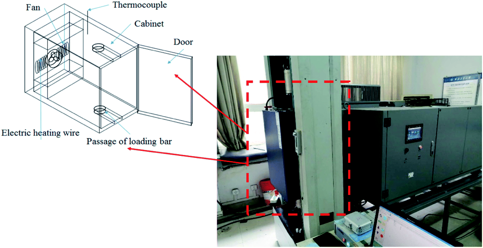 | ||
| Fig. 3 Equipment of the environment box with an electronic universal tester. | ||
4. Results and discussion
4.1. Latent heat of microencapsulated phase change composites
Fig. 4 shows the DSC curves for the solidification process of MPCMs. It can be found that two main transition peaks are clearly observed. This is because the paraffin contains numerous carbon atoms, and the α peak should be attributed to the heterogeneously nucleated rotator–liquid transition and β peak to the homogeneously nucleated crystal–rotator transition, as described in the ref. 30. The total latent heat of MPCMs is 125.1 J g−1 for C1, 128.2 J g−1 for C2 and 136.8 J g−1 for C3, respectively. It can be found that the latent heat capacity increases with an increase in the ratio of core to shell. It can also be seen from Fig. 3 that the phase transition starts from 60 °C, and then ends at 80 °C, and the maximum rate of latent heat absorption occurs at 71.1 °C for C1; the phase transition starts from 60 °C, and then ends at 80 °C, and the maximum rate of latent heat absorption occurs at 71.4 °C for C2; the phase transition starts from 60 °C, and then ended at 75 °C, and the maximum rate of latent heat absorption occurs at 72.6 °C for C3, respectively. This means that the maximum rate of latent heat absorption also increases with an increase in the ratio of core to shell.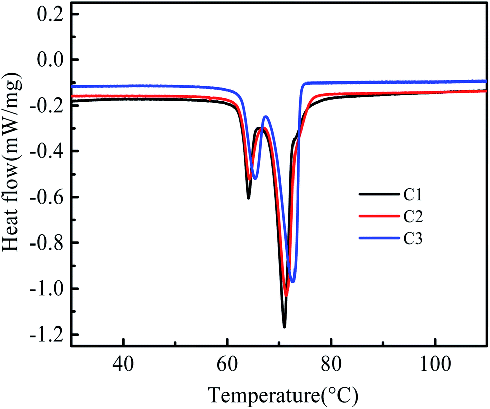 | ||
| Fig. 4 DSC curves of microencapsulated phase change composites. | ||
4.2. Mechanical properties for microencapsulated phase change composites
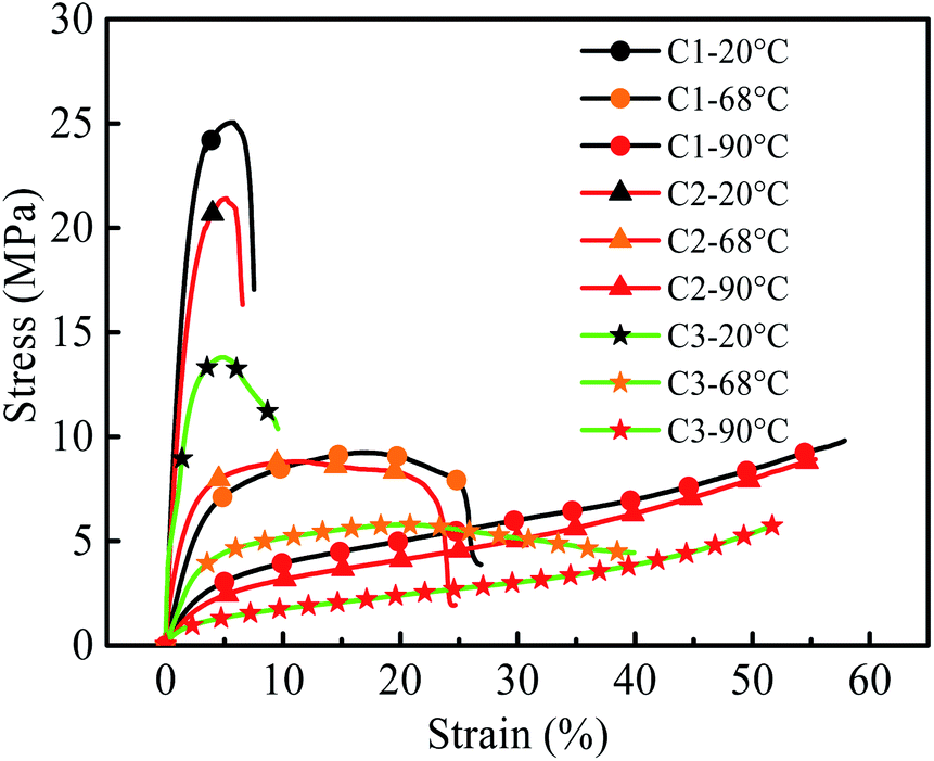
Compressive stress–strain curves for three different volume fraction ratios of core to shell (70:30, 90:10 and 96:4) at temperatures of 20 °C, 68 °C and 90 °C at a constant strain rate of 1 × 10⁻⁴ s−1 are displayed in Fig. 5. It can be found that the stress for three cases decreases with an increase in temperature. At 20 °C, for the case without phase transition, the stress increases exponentially, and after reaching the maximum, it decreases rapidly. This illustrates that at this stage, the deformation mode belongs to a brittle fracture status. When the temperature reaches up to the transformation temperature (68 °C), the stress increases slowly and then decreases. This is because the brittle deformation behavior is improved, and the strength decreases while the plasticity increases. When the temperature exceeds the phase transition temperature (90 °C), the stress slowly increases linearly, and the mechanical properties of the test sample display an obviously softening phenomenon, which shows no obvious failure stress, and only the stress gradually increases after the compaction. Besides, the maximum peak stress of C1 can reach up to 25 MPa, which is the highest compared with that of C2 and C3 in three conditions, and this illustrates that the shell plays the main role in the process of bearing external force.
 | ||
| Fig. 5 Stress–strain curve at temperatures of 20 °C, 68 °C and 90 °C, respectively. | ||
Fig. 6 shows photographs of typical test pieces before and after compression at temperatures of 20 °C, 68 °C and 90 °C, respectively. It can be seen that when the compressed temperature is set at 20 °C before the phase transition, the samples show an obvious brittle fracture with more obvious shear bands and cracks. At 68 °C during the phase transition, the mechanical properties of the samples show that the toughness increases, and the failure mode shows certain toughness and brittle fracture cracks. At 90 °C after the phase transition, the samples show obvious toughness and its height decreases. The material has no obvious brittle failure or shear band failure. It can be seen that the phase change composite has an evident liquid outflow, which is the paraffin in the microcapsule box transformation material.
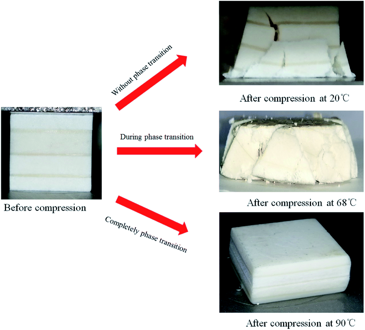 | ||
| Fig. 6 Pictures of before and after compression at temperatures of 20 °C, 68 °C, 90 °C, respectively. | ||
At first, at 20 °C, the phase change material paraffin is in a completely solid state. Under the protection of the shell, its strength is high, up to 25.05 MPa (for C1), which is about 10 times higher than that of pure paraffin. As the content of the shell becomes lesser and lesser, its strength becomes lower and lower (21.41 MPa for C2 and 13.80 MPa for C3) because the shell with high strength provides a lot of support for the strength. With the increase in temperature, particularly after exceeding the phase transition temperature of paraffin, paraffin becomes liquid. At this time, the strength mainly comes from two factors: one is the compressive strength of the shell itself (taking the test piece as a whole), and the other is the strength of the shell to resist tension under pressure (taking a microcapsule as a whole). As the material of the shell is the same, the greater the content (proportion) of the shell per unit volume, the greater its strength, and the corresponding yield strength is about 1.64 MPa, 1.51 MPa, 0.73 MPa for C1, C2, and C3, respectively.
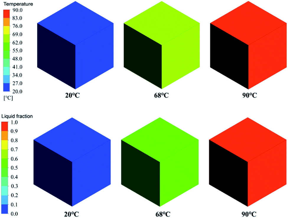
Those phenomena also can be also further illustrated by Fig. 7.
 | ||
| Fig. 7 Simulation of temperature and liquid fraction contour at temperatures of 20, 68, 90 °C, respectively. | ||
In order to explain the mechanical properties of MPCMs under working conditions, the temperature and liquid fraction contours are calculated using the ANSYS Fluent software. The uniform temperatures for all the surfaces of the simulation model are adopted. The detailed process can be referred from Soares et al.31 Fig. 7 shows the simulation results of the temperature and liquid fraction contours at the temperatures of 20 °C, 68 °C, and 90 °C, respectively. It can be found that temperatures of the MPCMs at three conditions show uniform distribution. This indicates that the heat in the box is uniform. The liquid fraction contours change from 0 to 0.6 and then to 1.0, which represents the conditions before the phase transition, during the phase transition and after the phase transition, respectively.
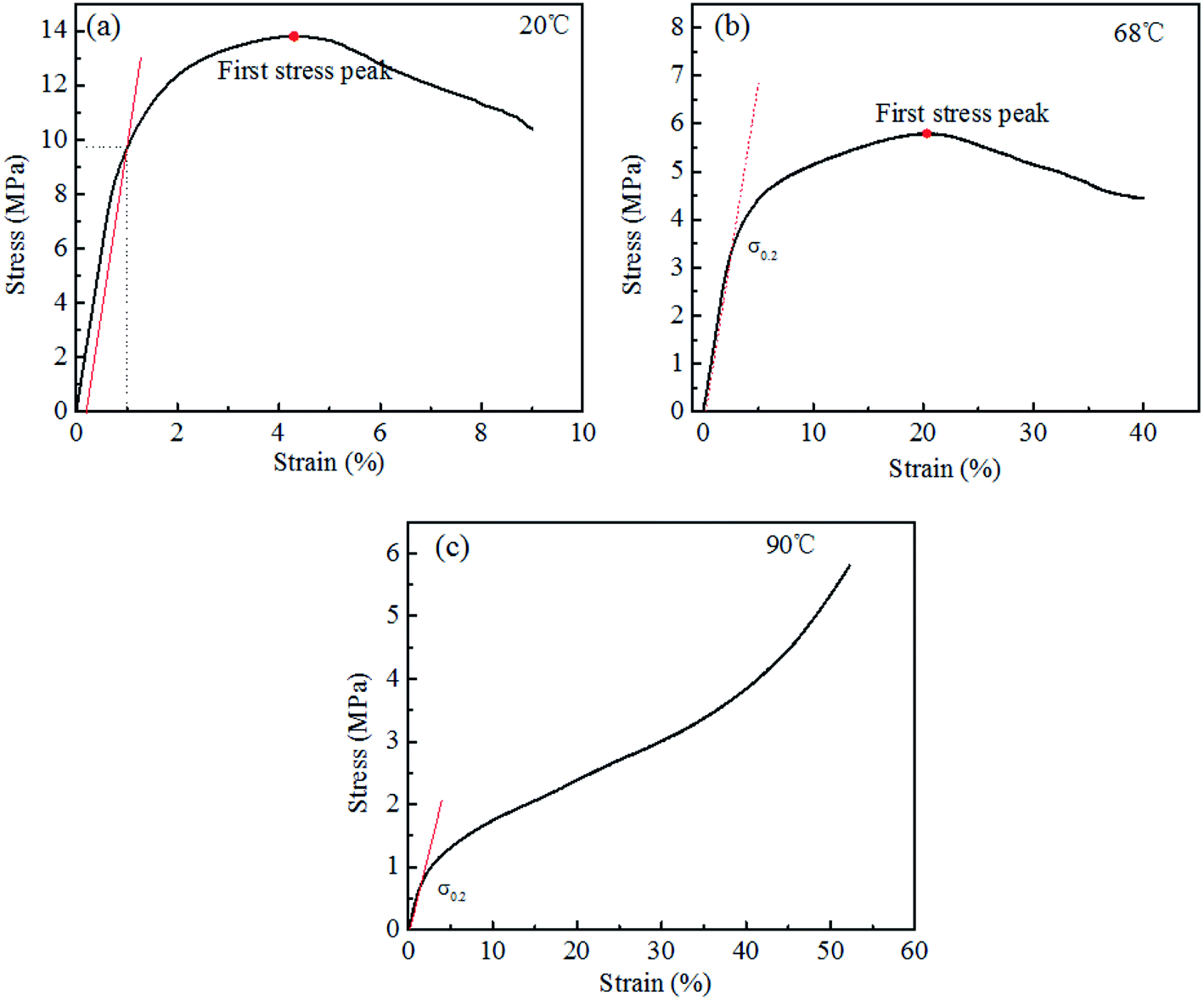
In order to obtain the basic mechanical properties of the MPCMs at temperatures of 20, 68, 90 °C, the stress–strain curves are analyzed, which is shown in Fig. 8. We find that the slope product of the initial stage of the stress–strain curve is the elastic modulus. When the strain reaches 0.2%, the corresponding stress is called the yield stress. For comparison, the first maximum stress is also calculated. The elastic modulus, yield strength, and first stress peak at different test temperature are shown in Table 1. It is shown that the elastic modulus, yield strength, and first stress peak increases with an increase in the volume fraction ratio of core to shell, while it decreases with the increase in temperature.
 | ||
| Fig. 8 Analysis of the stress–strain curve, which is used to extract the elastic modulus, yield strength and first stress peak. | ||
| Materials | Test temperature (°C) | Elastic modulus E (MPa) | Yield strength σ0.2 (MPa) | First stress peak (MPa) |
|---|---|---|---|---|
| C1 | 20 | 1546.61 | 13.09 | 25.05 |
| 68 | 236.17 | 4.79 | 9.24 | |
| 90 | 108.27 | 1.64 | — | |
| C2 | 20 | 1174.94 | 11.07 | 21.41 |
| 68 | 467.72 | 4.55 | 8.81 | |
| 90 | 77.77 | 1.51 | — | |
| C3 | 20 | 1945.09 | 9.68 | 13.80 |
| 68 | 142.62 | 3.74 | 5.79 | |
| 90 | 54.41 | 0.73 | — |
In this study, we mainly focus on the mechanical properties of microencapsulated phase change composites during a supersonic cruise. This part has never been reported in the literature, so it is difficult to compare with the other works. In summary, we can find that the maximum rate of latent heat adsorption for MPCMs is at about 70 °C. The structural strength of the MPCM structure can afford the aerodynamic force around the aircraft. The above MPCM structure can be used during cruise for the supersonic aircraft. The latent heat capacity increases with increase in the ratio of core to shell, while the peak stress decreases with an increase in the ratio of core to shell, which means a thorough consideration of the percentage of MPCMs should be done for the optimal MPCM thermal protection system of the supersonic aircraft.
5. Conclusions
The present work experimentally studies the change process of thermal storage and mechanical properties for the microencapsulated phase change composites during cruise for the supersonic aircraft. The influences of the volume fraction ratio of core to shell on the mechanical properties of microencapsulated phase change composites in the working condition are discussed. The latent heat capacity increases with increase in the ratio of core to shell. The temperature region for the MPCM phase transition ranges from 60 °C to 80 °C and the maximum rate of latent heat adsorption is at about 70 °C. Different deformation modes are found in three conditions. The deformation mode changes the brittle fracture to plasticity during the phase transition. The mechanical properties of the phase change composites decreases at three cases of without phase transition, during phase transition and complete phase transition, and also decreases with an increase in temperature. Therefore, a thorough consideration of the percentage of MPCMs is needed for the thermal protection of the supersonic aircraft.Conflicts of interest
There are no conflicts to declare.Acknowledgements
This work was supported by the National Natural Science Foundation of China (No. 51806177).References
- O. Mesalhy, K. Lafdi and A. Elgafy, Carbon foam matrices saturated with PCM for thermal protection purposes, Carbon, 2006, 44, 2080–2088 CrossRef CAS.
- A. Elefsiniotis, N. Kokorakis, T. Becker and U. Schmid, A novel high-temperature aircraft-specific energy harvester using PCMs and state of the art TEGs, Mater. Today: Proc., 2015, 2, 814–822 Search PubMed.
- X. Zhu, X. Li, J. Shen, B. Wang, Z. Mao, H. Xu, X. Feng and X. Sui, Stable microencapsulated phase change materials with ultrahigh payload for efficient cooling of mobile electronic devices, Energy Convers. Manage., 2020, 223, 113478 CrossRef CAS.
- X. Wu, Z. Zhu, H. Zhang, S. Xu, Y. Fang and Z. Yan, Structural optimization of light-weight battery module based on hybrid liquid cooling with high latent heat PCM, Int. J. Heat Mass Transfer, 2020, 163, 120495 CrossRef.
- T. F. Xu, H. L. Tian, H. X. Zhu and J. C. Cai, China actively promotes CO2 capture utilization and storage reasearch to achieve carbon peak and carbon neutrality, Adv. Geo-Energy Res., 2022, 6(1), 1–13 CrossRef.
- H. Wang, Z. G. Qu, Y. Yin, J. F. Zhang and P. W. Ming, Thermal management for hydrogen charging and discharging in a screened metal-organic framework particle tank, ACS Appl. Mater. Interfaces, 2021, 13, 61838–61848 CrossRef CAS PubMed.
- B. Li, T. Liu, L. Hu, Y. Wang and L. Gao, Fabrication and properties of microencapsulated paraffin@ SiO2 phase change composite for thermal energy storage, ACS Sustainable Chem. Eng., 2013, 1, 374–380 CrossRef CAS.
- X. Huang, C. Zhu, Y. Lin and G. Fang, Thermal properties and applications of microencapsulated PCM for thermal energy storage: A review, Appl. Therm. Eng., 2019, 147, 841–855 CrossRef.
- F. Marske, J. M. S. Silva, R. B. Wehrspohn, T. Hahna and D. Enk, Synthesis of monolithic shape-stabilized phase change materials with high mechanical stability via a porogen-assisted in situ sol–gel process, RSC Adv., 2020, 10, 3072 RSC.
- Z. H. Rao, X. Y. You, Y. T. Huo and X. J. Liu, Dissipative particle dynamics study of nanoencapsulated thermal energy storage phase change material, RSC Adv., 2014, 4, 39552 RSC.
- T. Y. Zhang, Q. Tang, H. L. Lu, S. Wang and L. Y. Sun, Numerical study of melted PCM inside a horizontal annulus with threads in a three-dimensional model, RSC Adv., 2015, 5, 12178 RSC.
- Y. Fang, Z. G. Qu and Y. D. Fu, Experimental study of the thermal characteristics of microencapsulated phase change composite cylinders, Appl. Therm. Eng., 2017, 114, 1256–1264 CrossRef CAS.
- V. Chalkia, N. Tachos, P. K. Pandis, A. Giannakas, M. K. Koukou, M. Gr. Vrachopoulos, L. Coelho, A. Ladavosc and V. N. Stathopoulos, Influence of organic phase change materials on the physical and mechanical properties of HDPE and PP polymers, RSC Adv., 2018, 8, 27438 RSC.
- J. J. Zhang, Z. G. Qu and Z. G. Jin, Experimental study on the thermal characteristics of a microencapsulated phase-change composite plate, Energy, 2014, 71, 94–103 CrossRef CAS.
- A. M. Borreguero, M. Carmona, M. L. Sanchez, J. L. Valverde and J. F. Rodriguez, Improvement of the thermal behaviour of gypsum blocks by the incorporation of microcapsules containing PCMS obtained by suspension polymerization with an optimal core/coating mass ratio, Appl. Therm. Eng., 2010, 30, 1164–1169 CrossRef CAS.
- L. Erlbeck, P. Schreiner, K. Schlachter, P. Dörnhofer, F. Fasel, F. J. Methner and M. Rädle, Adjustment of thermal behavior by changing the shape of PCM inclusions in concrete blocks, Energy Convers. Manage., 2018, 158, 256–265 CrossRef CAS.
- L. Cao and D. Zhang, Styrene-acrylic emulsion/graphene aerogel supported phase change composite with good thermal conductivity, Thermochim. Acta, 2019, 680, 178351 CrossRef CAS.
- A. H. N. Al-Mudhafar, A. F. Nowakowski and F. C. G. A. Nicolleau, Performance enhancement of PCM latent heat thermal energy storage system utilizing a modified webbed tube heat exchanger, Energy Rep., 2020, 6, 76–85 CrossRef.
- A. Alhusseny, N. Al-Zurfi, A. Nasser, A. Al-Fatlawi and M. Aljanabi, Impact of using a PCM-metal foam composite on charging/discharging process of bundled-tube LHTES units, Int. J. Heat Mass Transfer, 2020, 150, 119320 CrossRef.
- M. A. Ali, R. F. Viegas, M. S. Kumar, R. K. Kannapiran and M. Feroskhan, Enhancement of heat transfer in paraffin wax PCM using nano graphene composite for industrial helmets, J. Energy Storage, 2019, 26, 100982 CrossRef.
- Z. Tao, X. Chen, M. Yang, X. Xu, Y. Sun, Y. Li, J. Wang and G. Wang, Three-dimensional rGO@sponge framework/paraffin wax composite shape-stabilized phase change materials for solar-thermal energy conversion and storage, Sol. Energy Mater. Sol. Cells, 2020, 215, 110600 CrossRef CAS.
- K. Dong, N. Sheng, D. Zou, C. Wang, K. Shimono, T. Akiyama and T. Nomura, A high-thermal-conductivity, high-durability phase-change composite using a carbon fibre sheet as a supporting matrix, Appl. Energy, 2020, 264, 114685 CrossRef CAS.
- S. Dhivya, S. I. Hussain, S. Jeya Sheela and S. Kalaiselvam, Experimental study on microcapsules of Ag doped ZnO nanomaterials enhanced Oleic-Myristic acid eutectic PCM for thermal energy storage, Thermochim. Acta, 2019, 671, 70–82 CrossRef CAS.
- B. V. S. Dinesh and A. Bhattacharya, Effect of foam geometry on heat absorption characteristics of PCM-metal foam composite thermal energy storage systems, Int. J. Heat Mass Transfer, 2019, 134, 866–883 CrossRef.
- L. F. Cabeza, C. Barreneche, I. Martorell, L. Miró, S. Sari-Bey, M. Fois, H. O. Paksoy, N. Sahan, R. Weber, M. Constantinescu, E. M. Anghel, M. Malikova, I. Krupa, M. Delgado, P. Dolado, P. Furmanski, M. Jaworski, T. Haussmann, S. Gschwander and A. I. Fernández, Unconventional experimental technologies available for phase change materials (PCM) characterization. Part 1. Thermophysical properties, Renewable Sustainable Energy Rev., 2015, 43, 1399–1414 CrossRef CAS.
- Z. I. Djamai, A. S. Larbi, F. Salvatore and G. Cai, A new PCM-TRC composite: a mechanical and physicochemical investigation, Cem. Concr. Res., 2020, 135, 106119 CrossRef CAS.
- B. A. Young, Z. Wei, J. Rubalcava-Cruz, G. Falzone, A. Kumar, N. Neithalath, G. Sant and L. Pilon, A general method for retrieving thermal deformation properties of microencapsulated phase change materials or other particulate inclusions in cementitious composites, Mater. Des., 2017, 126, 259–267 CrossRef CAS.
- E. Gürbüz and S. Erdem, Development and thermo-mechanical analysis of high-performance hybrid fibre engineered cementitious composites with microencapsulated phase change materials, Constr. Build. Mater., 2020, 263, 120139 CrossRef.
- Z. Wei, G. Falzone, S. Das, N. Saklani, Y. Le Pape, L. Pilon, N. Neithalath and G. Sant, Restrained shrinkage cracking of cementitious composites containing soft PCM inclusions: a paste (matrix) controlled response, Mater. Des., 2017, 132, 367–374 CrossRef CAS.
- Z. G. Jin, Y. D. Wang, J. G. Liu and Z. Z. Yang, Synthesis and properties of paraffin capsules as phase change materials, Polymer, 2008, 49, 2903–2910 CrossRef CAS.
- N. Soares, N. Rosa, J. J. Costa, A. G. Lopes, T. Matias, P. N. Simões and L. Durães, Validation of different numerical models with benchmark experiments for modelling microencapsulated-PCM-based applications for buildings, Int. J. Therm. Sci., 2021, 159, 106565 CrossRef CAS.
| This journal is © The Royal Society of Chemistry 2022 |