
 Open Access Article
 This Open Access Article is licensed under a
 Creative Commons Attribution 3.0 Unported Licence
Thermal plasma gasification of organic waste stream coupled with CO2-sorption enhanced reforming employing different sorbents for enhanced hydrogen production†
Vineet Singh Sikarwar *abc,
Nageswara Rao Peelad,
Arun Krishna Vuppaladadiyamefg,
Newton Libanio Ferreirah,
Alan Mašlánia,
Ritik Tomarbi,
Michael Pohořelýb,
Erik Meersc and
Michal Jeremiáša
*abc,
Nageswara Rao Peelad,
Arun Krishna Vuppaladadiyamefg,
Newton Libanio Ferreirah,
Alan Mašlánia,
Ritik Tomarbi,
Michael Pohořelýb,
Erik Meersc and
Michal Jeremiáša
aInstitute of Plasma Physics of the Czech Academy of Sciences, v. v. i., Za Slovankou 1782/3, 182 00 Prague 8, Czech Republic. E-mail: sikarwar@ipp.cas.cz; Tel: +420 703666310
bDepartment of Power Engineering, University of Chemistry and Technology, Technická 5, 166 28 Prague 6, Czech Republic
cDepartment of Green Chemistry and Technology, Ghent University, 9000 Ghent, Belgium
dDepartment of Chemical Engineering, Indian Institute of Technology Guwahati, North Guwahati, Assam 781039, India
eDepartment of Civil & Environmental Engineering, Hong Kong Polytechnic University, 11 Yuk Choi Rd, Hung Hom, Hong Kong
fCollege of Science & Engineering, James Cook University, Townsville, Queensland 4811, Australia
gCatalytic Reaction Engineering Lab, Department of Chemical Engineering, Indian Institute of Technology Delhi, Hauz Khas, New Delhi, India
hUniversity Center of FEI, São Bernardo do Campo, SP 09850-901, Brazil
iORLEN Unipetrol Centre for Research and Education (ORLEN UniCRE), Areál Chempark, Litvínov-Záluží 43670, Czech Republic
First published on 21st February 2022
Abstract
In the past few years, rising concerns vis-à-vis global climate change and clean energy demand have brought worldwide attention to developing the ‘biomass/organic waste-to-energy’ concept as a zero-emission, environment-friendly and sustainable pathway to simultaneously quench the global energy thirst and process diverse biomass/organic waste streams. Bioenergy with carbon capture and storage (BECCS) can be an influential technological route to curb climate change to a significant extent by preventing CO2 discharge. One of the pathways to realize BECCS is via in situ CO2-sorption coupled with a thermal plasma gasification process. In this study, an equilibrium model is developed using RDF as a model compound for plasma assisted CO2-sorption enhanced gasification to evaluate the viability of the proposed process in producing H2 rich syngas. Three different classes of sorbents are investigated namely, a high temperature sorbent (CaO), an intermediate temperature sorbent (Li4SiO4) and a low temperature sorbent (MgO). The distribution of gas species, H2 yield, dry gas yield and LHV are deduced with the varying gasification temperature, reforming temperature, steam-to-feedstock ratio and sorbent-to-feedstock for all three sorbents. Moreover, optimal values of different process variables are predicted. Maximum H2 is noted to be produced at 550 °C for CaO (79 vol%), 500 °C for MgO (29 vol%) and 700 °C (55 vol%) for Li4SiO4 whereas the optimal SOR/F ratios are found to be 1.5 for CaO, 1.0 for MgO and 2.5 for Li4SiO4. The results obtained in the study are promising to employ plasma assisted CO2-sorption enhanced gasification as an efficacious pathway to produce clean energy and thus achieve carbon neutrality.
1. Introduction
The rising population with improving living standards have led to an increase in man-made greenhouse gas (GHG) emissions which in turn is causing global climate change. Carbon capture and storage have the potential to significantly contribute toward achieving the global warming targets set by the Intergovernmental Panel on Climate Change (IPCC)1 and at the Conference of the Parties (COP-21).2 In recent years, the elevating fears related to climate change coupled with increasing energy demand have brought the focus to developing the ‘biomass/waste-to-energy’ concept as an eco-friendly and sustainable pathway to quench global energy thirst. The characteristics of biomass such as its replenishable and carbon-neutral nature make it a lucrative energy resource.3 More importantly, it can be altered to a ‘carbon negative’ resource if the carbon is captured during the transformation process. This concept of coupling biomass (or organic waste)-to-energy system with carbon capture and storage (CCS) system is popularly known as BECCS (bioenergy with carbon capture and storage).4It is worth noting that bioenergy can play a crucial part in curbing climate change, however, it includes grave challenges such as the efficacies of bio-based energy systems and land use practices. In the European Union (EU), the influence of bioenergy (and energy from other organic wastes) on climate has crucial significance being the largest replenishable energy source employed.5 It is encouraging to learn that in order to accomplish the renewable energy targets by 2020, most of the EU nations have enhanced the usage of biomass (wood). Furthermore, apart from a few solid (such as pellets) and liquid biofuels which are obtained from other countries, EU uses the bioenergy generated within its states.
It is worth noting that the philosophy of BECCS is not emphatically defined and therefore, encompasses diverse industrial and energy technologies (biomass combustion for power generation, bio-refineries, biomass transformation to liquid/gaseous fuels, etc.) with varying carbon dioxide discharges. In past few decades, several researchers have been working on waste/biomass gasification to generate clean energy coupled with safe and efficient waste management.6 The application of advanced thermal plasma technology for valorizing different organic waste streams (including biomass and hazardous waste streams) has gained attention in past years. It is on account of high temperatures and high energy fluxes gained from thermal plasma which in turn provide high destruction efficiency coupled with the ability to provide useful products such as good quality syngas, slag, etc.6 In addition, eco-friendliness and operational control are other benefits with this technology.
One of the pathways to realize BECCS is via CO2-sorption process coupled with thermal plasma gasification where in situ sorption of carbon dioxide takes place. It can be attained by feeding the sorbents to steam reformers7 or water gas shift reactors.8 The sorbent (such as calcium oxide, magnesium oxide, etc.) adsorbs CO2 and shifts the reaction to right hand side with higher generation of H2. The sorbent carbonate is then decarbonized to replenish the sorbent and to produce a concentrated CO2 stream.
The fundamental idea behind sorption enhanced gasification is to capture CO2 inside the reactor (E2, E3, E4 and E6 in Table 1) as soon as it is generated, consequently shifting the equilibrium according to Le Chatelier's principle, with an enhancement in hydrogen production.9 Carbon capture reactions (E10, E12, E14 in Table 1) occur at comparatively lower temperatures to adsorb CO2 thus forming sorbent carbonates coupled with heat release. On the other hand, at elevated temperatures, decarbonation reactions (E11, E13, E15 in Table 1) occur to recover the sorbent with concentrated CO2 discharge. This CO2 stream can be used as a feedstock for chemical synthesis or can be sent to geological storages. Several research works on CO2-sorption enhanced gasification have been carried out worldwide using calcium oxide,10–13 however, a very few have reported any other sorbent.14–16
| Equation number | Reaction name/type | Chemical equation |
|
|---|---|---|---|
| E1 | Water gas-I | C + H2O ⇌ CO + H2 | +131.0 |
| E2 | Water gas-II | C + 2H2O ⇌ CO2 + 2H2 | +90.1 |
| E3 | Water gas shift | CO + H2O ⇌ CO2 + H2 | −41.2 |
| E4 | Methane reforming | CH4 + 2H2O ⇌ CO2 + 4H2 | +206.0 |
| E5 | Boudouard | C + CO2 ⇌ 2CO | +172.0 |
| E6 | Oxidation-I | C + O2 ⇌ CO2 | −394.0 |
| E7 | Oxidation-II | 2C + O2 ⇌ 2CO | −111.0 |
| E8 | Methanation-I | C + 2H2 ⇌ CH4 | −72.8 |
| E9 | Methanation-II | 2CO + 2H2 ⇌ CH4 + CO2 | −247.0 |
| E10 | Carbonation (Ca) | CaO + CO2 ⇌ CaCO3 | −178.9 |
| E11 | Decarbonation (Ca) | CaCO3 ⇌ CaO + CO2 | +178.9 |
| E12 | Carbonation (Mg) | MgO + CO2 ⇌ MgCO3 | −117.9 |
| E13 | Decarbonation (Mg) | MgCO3 ⇌ MgO + CO2 | +117.9 |
| E14 | Carbonation (Li4SiO4) | Li4SiO4 + CO2 ⇌ Li2SiO3 + Li2CO3 | −142.0 |
| E15 | Decarbonation (Li4SiO4) | Li2SiO3 + Li2CO3 ⇌ Li4SiO4 + CO2 | +142.0 |
In the current investigation, coupling of thermal plasma gasification with CO2-sorption enhanced reforming in two different stages is explored from thermodynamic point of view employing three different classes of sorbents namely, calcium based sorbents (CaO) (as a model compound for high temperature sorbent), magnesium based sorbents (MgO) (as a model compound for low temperature sorbent) and alkali ceramic based sorbents (Li4SiO4) (as a model compound for intermediate temperature sorbent). Refuse derived fuel (RDF) is taken as a model compound for feedstock. The cardinal reason for the choice of model compound includes its ample availability nowadays. Moreover, its contains a lot of hydrogen which in turn is theoretically good for the production of hydrogen from the waste.
It is worth noting that plasma gasification of RDF is beneficial in comparison to conventional gasification pathways (such as fluidized bed gasification) in a way that the produced synthesis gas does contain only traces of tars (tens of mg m−3![[thin space (1/6-em)]](https://www.rsc.org/images/entities/char_2009.gif) 19 as compared to tens of g m−3 in fluidized bed gasification),20 which renders the usability of the gas for downstream enhanced gas reforming better in terms of better longevity of sorbents. The flip side of plasma gasification is the consumption of electricity for providing the energy for the allothermal process; but there is a strong possibility to adjust the power of the process to actual electricity prices in the distribution grid on account of strong flexibility of the process and therefore, it can be used as a means of transformation of surplus electricity into energy of hydrogen.21
19 as compared to tens of g m−3 in fluidized bed gasification),20 which renders the usability of the gas for downstream enhanced gas reforming better in terms of better longevity of sorbents. The flip side of plasma gasification is the consumption of electricity for providing the energy for the allothermal process; but there is a strong possibility to adjust the power of the process to actual electricity prices in the distribution grid on account of strong flexibility of the process and therefore, it can be used as a means of transformation of surplus electricity into energy of hydrogen.21
In the primary stage, thermal plasma assisted gasification of RDF takes place at higher temperatures and in the second stage, the gaseous products are reformed in the presence of sorbent at relatively low temperatures generating hydrogen rich high quality syngas coupled with in situ CO2 capture as depicted in Fig. 1. Dividing the whole process in two stages enables the individual sub-processes (plasma gasification and sorption enhanced reforming) to take place at their favorable temperatures. It is worth noting that regulating the reforming of pure gaseous products (from Step-I of the proposed process) is easier than the reforming of biomass-volatiles blend in the conventional single stage gasification.
 | ||
| Fig. 1 Schematic of the proposed two-steps sorption enhanced gasification with CO2 capture and clean energy production. | ||
No work to our knowledge has been published hitherto in the literature to examine the coupling of thermal plasma gasification of organic waste with sorption enhanced reforming in the presence of three different classes of sorbents for in situ CO2 capture via equilibrium modeling. In this study, we develop an equilibrium model for dual stage plasma assisted CO2-sorption enhanced gasification of RDF to evaluate the viability of proposed process in generating good quality hydrogen rich syngas. In addition, the objectives include the predictions of gas compositions, H2 yields, dry gas yields and LHVs as the functions of different classes of sorbents, gasification temperature, reforming temperature, steam-to-feedstock (S/F) ratio and sorbent-to-feedstock (SOR/F) ratio along with the deductions of optimal process conditions.
2. Methodology
A non-stoichiometric equilibrium model was developed employing the Gibbs free energy minimization approach in Aspen Plus (V11.0) thermodynamic environment using refuse derived fuel (RDF) as the model compound. The RDF used was a product from a sorting facility in Czech Republic (unrecyclable plastics mixed with unrecyclable paper and industrial wastes to meet the normalized composition). The proximate and ultimate analyses of the model compound (RDF) is given in Table 2.| Proximate analysis | RDF (wt%) | Ultimate analysis | RDF (wt%) |
|---|---|---|---|
| Fixed carbon | 9.15 | C | 62.17 |
| Volatile matter | 80.24 | H | 8.07 |
| Moisture | 1.47 | O | 18.52 |
| Ash | 9.14 | N | 0.59 |
| S | 0.01 |
The LHV (MJ Nm−3) of the product gas was computed based on the equation:9
| LHV = [((mCO × 126.36) + (mH2 × 107.98) + (mCH4 × 358.18))/1000] MJ Nm−3 | (E16) |
2.1 Assumptions in model formulation
Following assumptions were taken while developing the modeling framework: (i) all the state variables were constant inside both the reactors (gasifier and reforming reactor); (ii) the performance of the gasification reactor was not influenced by the particle size distribution of the feedstock;13 (iii) both the reactors were operated at isothermal conditions at 1 bar; (iv) pyrolysis took place rapidly generating hydrogen, carbon monoxide, carbon dioxide and methane as the cardinal gases;22 (v) pyrolysis occurred prior to the reforming reactions and char gasification (E1, E2, E5); (vi) lower heating value (LHV) were computed considering hydrogen, carbon monoxide and methane; (vii) ash was considered as a non-reactive solid; (viii) the enthalpy of formation, specific heat capacity and density were calculated using HCOALGEN and DCOALIGT property methods in Aspen Plus environment; (ix) the catalytic activities of the employed sorbents (CaO, MgO and Li4SiO4) were not considered; (x) the catalytic activity of thermal plasma was not considered.2.2 Model development
The gasification of biomass/wastes entails diverse overlapping stages (for example, drying, pyrolysis, partial oxidation and gasification). Devolatization of feedstock occurs followed by heterogeneous partial oxidation of char combined with gas phase reactions and tar cracking reactions. Simplistically, tar cracking can be depicted in E17.23| pCnHx ↔ qCmHy + rH2 | (E17) |
The diverse phases which were taken into account while developing the modeling framework were the thermal plasma generation, feedstock degradation, volatile reactions and gasification, reforming, CO2 sorption enhancement and solid–gas separation as depicted in Fig. 2. The flow rate of model compound (RDF) was taken as 100 kg h−1. Three different sorbents were employed, namely, CaO, MgO and Li4SiO4. Four different cases were considered by varying gasification temperature (GT) (from 800 to 1400 °C with an interval of 100 °C), reforming temperature (RT) (from 500 to 800 °C for CaO; 200 to 500 °C for MgO and 400 to 700 °C for Li4SiO4 with an interval of 50 °C), steam-to-feedstock ratio (S/F) (from 0.8 to 2.0 with an interval of 0.2) and sorbent-to-feedstock ratio (SOR/F) (from 0.0 to 3.0 with an interval of 0.5). Each parameter was varied (keeping other variables constant) to evaluate its impact on the distribution of syngas constituents, hydrogen yield, dry gas yield and LHV and, to compute the optimal operational conditions. Water and argon were supplied to the plasma torch at constant rates of 16.8 kg h−1 and 3 kg h−1, respectively. The water was fed to the gasifier at varying rates (taking into account the water input in plasma torch) to achieve respective S/F ratio, for example, to achieve S/F of 0.8, 63.2 kg h−1 of water was fed to the gasifier. The sorbent was supplied to the reformer at varying rates to obtain respective SOR/F ratios.
 | ||
| Fig. 2 Flowsheet reflecting the simulation in Aspen Plus (V11.0). | ||
Description of the flowsheet can be found in Table S1 of the ESI.† With reference to Fig. 2, thermal plasma was generated in the Direct Current (DC) Plasma Torch where electricity, argon and water was fed. Heater served as the plasma torch and thermal plasma input was supplied to the gasifier. The feedstock (RDF) was heated in the Heater followed by feeding to the pyrolyzer. Aspen block RYield acted as the pyrolyzer due to its capability to deduce the yields form the complex feed (non-conventional materials such as biomass, wastes, coal, etc.). It is assumed that the reaction (E18) took place in the pyrolyzer.24
| CxHyOz → H2 + CO + CO2(g) + HC(g) + Tar(l) + Char(s) | (E18) |
It is worth noting that a calculator block was employed to compute the yields in RYield reactor based on the equations given by other authors22 as depicted in Table S2 of the ESI.† These empirical relations were temperature dependent and they closely deduced the yields.
The products from pyrolyzer were fed to gasifier along with the water for steam gasification. RGibbs reactor was employed as gasifier which works on the principle of Gibbs free energy minimization to perform the phase and equilibrium calculations and compute the final yields post gasification. It was supposed that the reactions mentioned in Table 1 (E1 to E9) occurred inside the gasifier.
The gaseous products of gasifier were fed to the reformer along with the sorbent where the reforming, carbonation and decarbonation reactions took place. On the other hand, the solid products (solid carbon and ash) were separated using a Filter. Again, RGibbs reactor was used as the reformer. It is worth noting that in the absence of the loop, sorbent could not be regenerated. Therefore, fresh sorbent was continuously supplied to the reformer at varying feed rates. Finally, the products from the reformer were passed through filter to separate the solids and gases.
2.3 Model validation
The validation of the first stage of proposed model (Fig. 3) was carried out using the experimental data realized by the experimental study in our institute (Institute of Plasma Physics of the Czech Academy of Sciences).25 The operating conditions were taken same as that described in the study where the feed rates of sawdust, pellets (spruce wood composition with 7.4% H2O and 6 mm diameter) and plastics were taken as respectively 30, 30 and 11.4 kg h−1, in the presence of CO2 as the oxidizing media at 1300 °C. The dry gas fractions forecasted by the proposed model for H2, CO, CO2 and CH4 are in good agreement with the experimental results and the deviations are well within the reasonable limits. | ||
| Fig. 3 Experimental results vs. modeling predictions taking three different feedstocks namely, (a) sawdust, (b) pellets and (c) plastics. | ||
No experimental study on two-stage sorption enhanced gasification of RDF with MgO and Li4SiO4 was available, so the experimental investigation by other authors26 using corn stalk as the feedstock in the presence of CaO for two-stage pyrolysis-gasification was chosen as a close proxy. In order to validate the mathematical model, both gasification (pyrolyzer and gasifier) and reforming temperatures were taken as 650 °C, CaO/F as 2, S/F as 1 at 1 bar pressure and the chemical composition of corn stalk was used, and resulting syngas components were compared to the experimental data. The amounts of respective syngas components (H2, CO, CO2 and CH4) were deduced. The proposed model predicted 88.6 vol% H2, 3.7 vol% CO, 1.4 vol% CO2 and 5.2 vol% CH4 whereas the experimental values were 85.1 vol% H2, 5.2 vol% CO, 0.1 vol% CO2 and 9.6 vol% CH4. Therefore, the modeling deductions were found to be reasonably close to the experimental data.
3. Predictions and discussions
3.1 Impact of gasification temperature
The influence of gasification temperature (in Stage-I) was assessed on syngas constituents, hydrogen yield, dry gas yield and LHV employing all three different sorbents namely, CaO, MgO and Li4SiO4 taking one at a time. The temperature of gasifier was varied from 800 to 1400 °C keeping S/F at 1 and SOR/F at 2. The reforming temperature was kept constant at 650 °C, 250 °C and 500 °C, respectively, for CaO, MgO and Li4SiO4. The choice of reforming temperatures was based on the thermodynamics of the sorption process with regard to different sorbents.10,17,27,28 The distribution of gaseous species is reflected in Fig. 4.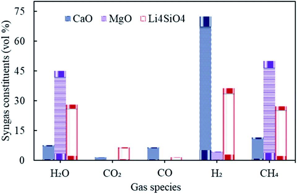 | ||
| Fig. 4 Variation in syngas constituents with variable gasification temperature (800 to 1400 °C) with CaO, MgO and Li4SiO4. | ||
It was found that the molar fractions of syngas constituents remained the same for the entire range of gasification temperature keeping all other variables constant. As the compositions were deduced at equilibrium while keeping the reforming temperatures constant for each of the sorbent. This explained the constant distribution of syngas components with varying gasifier's temperature. It is worth noting that the gas compositions were found to be different for diverse gasification temperatures in Stage-I (as shown in Fig. S1 in the ESI†), however, after undergoing the sorption enhanced reforming in the reformer (Stage-II), the distribution of species at equilibrium became constant and thus, the effect of gasification temperature was buffered. It should be noted that this investigation was purely a thermodynamic (without kinetic considerations) study and the authors were aware that in real world scenario, some reactions would not be feasible due to kinetic limitations, mainly at the low temperatures (with MgO).
Referring to Fig. 4, hydrogen amounts employing CaO (at 650 °C) was higher with 72 vol% as compared to Li4SiO4 (at 500 °C) with 36 vol% and MgO (at 250 °C) with 4.4 vol%. On the other hand, CH4 was the highest (50 vol%) while MgO was employed. Reactions E1 and E2 are endothermic in nature and therefore, they were favored more at 650 °C vis-à-vis 500 °C and 250 °C. Also, endothermic methane reforming (E4) was strengthened in case of CaO and Li4SiO4 as compared to MgO, consuming methane and generating H2. This was the reason of more CH4 production (50 vol%) with MgO. It was deduced when CaO and Li4SiO4 were employed as sorbents, around 1.5 vol% and 6.5 vol% respectively of CO2 were generated on account of sorption by sorbents (E10 and E14) which in turn shifted the equilibrium for water gas shift (E3) as per Le Chatelier's principle producing more H2. When Mg based sorbent was used in the reformer, 0.22 vol% of CO2 was reported on account of adsorption by MgO (E12). Maximum H2O (45 vol%) and negligible CO was found in case of MgO on account of reverse water gas reactions (E1 and E2) due to lower reforming temperature of 250 °C.
As seen in Table S3 of ESI,† maximum H2 yield was obtained as 0.14 kg kg−1 of fuel for CaO and minimum as 0.0057 kg kg−1 of fuel for MgO. On the other hand, the dry gas yield was found to be minimum with a value of 0.53 kg kg−1 of fuel for syngas when MgO was employed as sorbent while it was the highest for Li4SiO4 (0.68 kg kg−1 of fuel). The value of LHV was maximum for MgO induced sorption enhanced reforming as compared to other employed sorbents. It was on account of higher CH4 concentrations in the gas which in turn contributed more to LHV calculations.
3.2 Impact of reforming temperature
The distribution of syngas constituents along with carbon dioxide capture, dry gas yield and LHV were examined as a function of varying reforming temperatures (500 to 800 °C for CaO, 200 to 500 °C for MgO and 400 to 700 °C for Li4SiO4) in Stage-II, keeping the gasification temperature in Stage-I constant at 1000 °C. The sorbent-to-feedstock ratio was 2 and steam-to-feedstock ratio was 1 for the entire investigation. The alterations in gas species are depicted in Fig. 5(a)–(c) respectively, when CaO, MgO and Li4SiO4 were fed in the reformer at Step-II.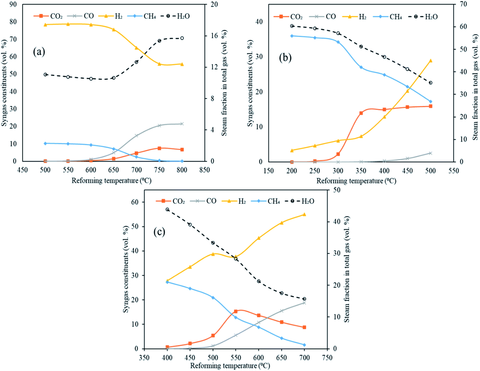 | ||
| Fig. 5 Variation in syngas constituents with variable reforming temperature employing three classes of sorbents (a) CaO sorbent (500 to 800 °C), (b) MgO sorbent (200 to 500 °C) and Li4SiO4 sorbent (400 to 700 °C). Note: x-axes and y-axes have different ranges for each set of graphs. | ||
Referring to Fig. 5(a), employing CaO as sorbent in the reformer, the amounts of H2 decreased from 78 vol% at 500 °C to 56 vol% at 800 °C. A sharp decrease after 650 °C was noticed on account of optimal range of sorption temperature (500 to 650 °C) for CaO.10,17 CO2 was captured by CaO from 500 to 650 °C via carbonation reaction (E10) forming CaCO3. Beyond 650 °C, decarbonation began forming CO2 and sorbent. It was for the same reason that CO2 molar fraction increased beyond 650 °C from 1.5 vol% to 6.6 vol% at 800 °C. Moreover, this could be because of the steam methane reforming (E4) and water gas reaction (E2) also. On the other hand, CO continuously enhanced from 0.023 to 22 vol% as the water gas reaction (E1) was favored while CH4 consistently decreased as the methane reforming (E4) was strengthened, as the reforming temperature was raised. In addition, the decrease in the hydrogen and increase in the CO could possibly because of the reverse water gas shift reaction (E3).
When MgO was employed as the sorbent in the reformer, a uniform increase in H2 was noticed from 3.3 vol% at 200 °C to 29 vol% at 500 °C (Fig. 5(b)). This can be explained on the basis of synergistic effects of reforming reactions (E1, E2 and E4) and water gas shift (E3). However, the molar fractions of H2 is lower as compared to the CaO case because E1, E2 and E4 reactions are not very dominant due to comparatively lower temperatures of reformer. This also explains the higher concentrations of CH4 and steam fraction throughout the entire temperature range. More importantly, a clear rise in CO2 was seen from 300 °C due to decarbonation of MgCO3 (E13). Also, reactions E2 and E4 were bolstered leading to higher CO2 generation whereas reaction E1 was strengthened giving higher CO, with rising temperatures.
As can be seen in Fig. 5(c), a considerable and continuous rise of H2 was observed with rising temperature with 28 vol% at 400 °C to 55 vol% at 700 °C when lithium orthosilicate was used as a sorbent in reformer. It was on account of water gas (E1 and E2) and methane reforming (E4). This also led to decreasing CH4 and increasing CO amounts. A rise in CO2 was found from 0.66 vol% at 400 °C to 15 vol% at 550 °C as E2 and E4 reactions were favored. However, carbonation was initiated at 550 °C leading to the capture of CO2 by Li4SiO4 and formation of Li2SiO3 and Li2CO3.28 This led to a sharp decrease in CO2 fractions to 8.7 vol% at 700 °C.
The maximum hydrogen yields were noticed at the respective upper limits of reforming temperatures for MgO (500 °C) and Li4SiO4 (700 °C) respectively as 0.057 and 0.145 kg kg−1 of fuel as depicted in Fig. 6. However, for CaO, the hydrogen yield increased from 0.139 kg kg−1 of fuel at 500 °C to 0.153 kg kg−1 of fuel at 700 °C and then dropped to 0.151 kg kg−1 of fuel at 800 °C. Therefore, the maximum hydrogen yield with CaO was obtained at 700 °C beyond which desorption of CO2 began. A fairly sharp increase was seen for MgO and Li4SiO4 for their respective temperature ranges. The dry gas yield was found to increase continuously from 0.28 to 1.4 kg kg−1 of fuel for CaO, from 0.42 to 1.08 kg kg−1 of fuel for MgO and from 0.40 to 1.36 kg kg−1 of fuel for Li4SiO4 when the reforming temperatures were raised from 500 to 800 °C, 200 to 500 °C and 400 to 700 °C, respectively, while employing CaO, MgO and Li4SiO4 in reformer at Stage-II. When CaO was used as a sorbent, LHV decreased from 12 to 8.7 MJ Nm−3. Same trend was observed for MgO sorbent (13 to 9.6 MJ Nm−3) and Li4SiO4 sorbent (13 to 8.8 MJ Nm−3). The contribution of CH4 is maximum while deducing LHV and in all the three cases, CH4 amounts were decreasing leading to a drop in LHV as depicted in Table S4 of ESI.†
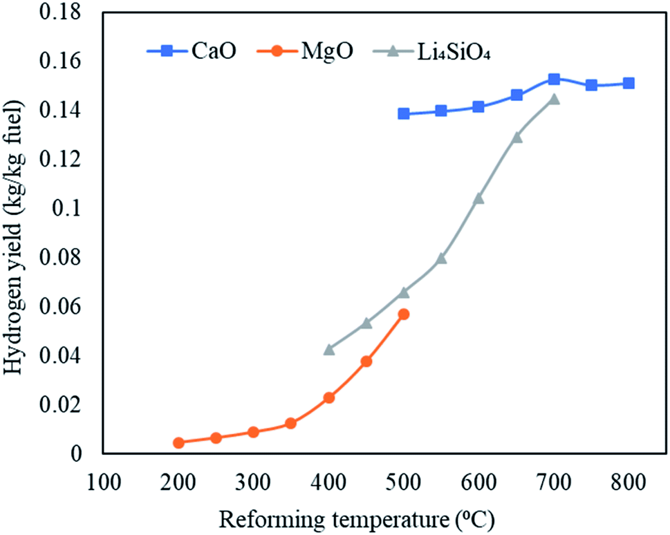 | ||
| Fig. 6 Variation in hydrogen yields (kg kg−1 fuel) with variable reforming temperature employing three classes of sorbents namely, CaO sorbent (500 to 800 °C), MgO sorbent (200 to 500 °C) and Li4SiO4 sorbent (400 to 700 °C). | ||
3.3 Impact of steam-to-feedstock ratio (S/F)
Steam is one of the most significant components in conventional plasma gasification and in conventional sorption enhanced gasification as it is needed for water gas (E1 and E2), methane reforming reaction (E4) and water gas shift (E3). This necessitates the exploration of steam feed rate in the gasifier in Stage-I of the current study. The total steam feed rate (steam input to plasma torch plus steam input to gasifier) was varied from 80 kg h−1 to 200 kg h−1 with an interval of 20 kg h−1 (S/F = 0.8 to 2.0). The other variables were constant with gasification temperature at 1000 °C, reforming temperature at 650 °C for CaO, 250 °C for MgO and 500 °C for Li4SiO4 and SOR/F at 2. The impact on the distribution of syngas components, H2 yield, dry gas yield and LHV were deduced as a function of varying S/F.Fig. 7(a)–(c) emphatically revealed the trend of carbon dioxide and other syngas distribution employing respectively CaO, MgO and Li4SiO4, when steam feed rate was raised from 80 kg h−1 to 200 kg h−1. A gradual enhancement in carbon dioxide was noticed with increasing S/F. It can be explained on the basis of alterations in partial pressure in the reaction system. As the amount of steam was increased, its partial pressure was raised leading to the shift of the water gas shift reaction (E3) towards higher production of H2 and CO2. This effect was mild when MgO was employed as sorbent and therefore, CO2 was found to be almost constant throughout the entire range of S/F. It should be noted that due to low temperature, the reactions of methanation (E8, E9) took place (mainly at the MgO case) because they were favored thermodynamically, however, under real conditions they are very slow at the mentioned temperatures and, therefore, could not happen to such extent without a special Ni catalyst and higher pressure and with inherent technological complications.29 Furthermore, it was noticed that H2 was first increased from 72 to 75 vol% and then decreased to 68 vol% for CaO sorbent. In the case of Li4SiO4, H2 concentration remained firstly decreased (from 37 to 34 vol%) and then was almost constant at 34 vol% with the increase of steam-to-feedstock ratio. On the other hand, H2 amounts increased mildly when MgO sorbent was fed to reformer. In the abundance of steam, methane reforming was dominant and thus produced CO2 and H2 at the cost of CH4 explaining a uniform reduction in CH4 for all three sorbents. It was seen that below certain steam-to-feedstock ratios, the variation in syngas composition was minimal on account of insufficient steam availability needed for steam reforming reactions. The change in the composition was marginal below S.F of 1.4 in the case of CaO sorbent. The alteration in H2, CO2 and CO while employing Li4SiO4 at S/F above 1.4 was found to be very mild. The deduction of trend in case of MgO was ambiguous.
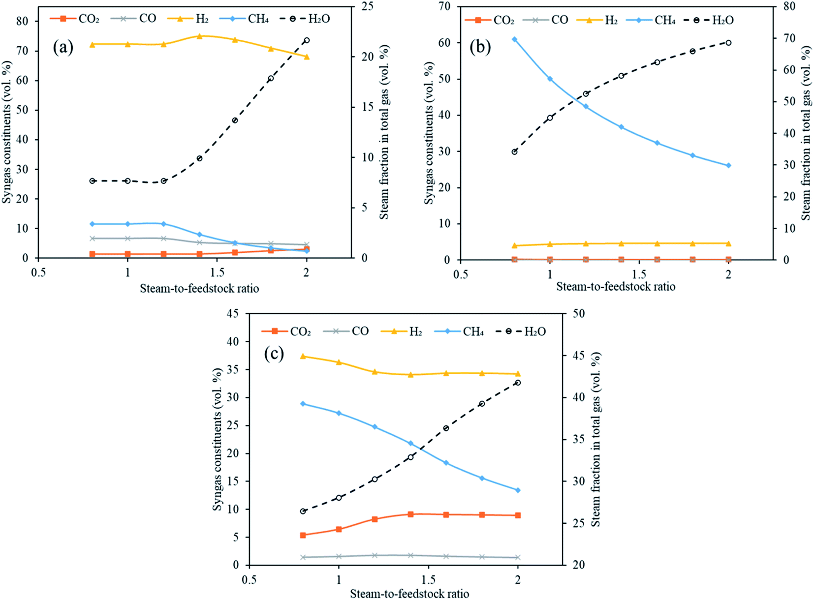 | ||
| Fig. 7 Variation in syngas constituents with variable steam-to-feedstock ratio (0.8 to 2.0) employing (a) CaO sorbent, (b) MgO sorbent and (c) Li4SiO4 sorbent. Note: y-axes have different ranges for each set of graphs. | ||
It is emphatically revealed in Table S5 of ESI† that the maximum yields of H2 were noticed for all the three classes of sorbents namely CaO, MgO and Li4SiO4 at S/F of 2. Different trends in the dry gas yields during sorption enhanced gasification employing three different sorbents with increasing steam feeding rate (80 to 200 kg h−1) were noted. The highest gas yield recorded were 0.70 kg kg−1 of fuel, 0.53 kg kg−1 of fuel and 1.1 kg kg−1 of fuel when respectively, CaO, MgO and Li4SiO4 were fed to reformer as CO2 sorbents at S/F of 2. The LHV showed a decreasing trend with enhancing S/F on account of reducing methane concentrations. The highest LHV was found to be 13 MJ Nm−3, 22 MJ Nm−3 and 15 MJ Nm−3 at S/F of 0.8, respectively for CaO, MgO and Li4SiO4. The reason of high LHV for MgO sorbent was a greater molar fraction of CH4 at 0.8 S/F.
3.4 Impact of sorbent-to-feedstock ratio (SOR/F)
Three classes of sorbents namely, low temperature sorbent (MgO), intermediate temperature sorbent (Li4SiO4) and high temperature sorbent (CaO) were used in the Stage-II in reformer in the current investigation with an objective to capture CO2 in situ and enhance H2 generation. The influence of sorbent feed rate (0 to 300 kg h−1 with an interval of 50 kg h−1) on H2 yield, carbon dioxide capture, syngas constituents, dry gas yield and LHV was examined. The gasifier temperature was constant at 1000 °C, reformer temperature at 650 °C for CaO, 250 °C for MgO and 500 °C for Li4SiO4 with S/F ratio at 1.It is worth noting that the underlying principle of sorption enhanced gasification is sorption of CO2 by the employed sorbent which in turn shifts the equilibrium in water gas shift (E3) thus enhancing the H2 production. The sorbent after capturing the CO2 forms carbonate and the reactions are known as carbonation (E10, E12 and E14) with the release of energy. At elevated temperatures (different for different sorbents), decarbonation takes place (E11, E13 and E15) where sorbent is regenerated with the release of concentrated stream of CO2 which may be employed as a feedstock for chemical synthesis or may be sent to geological storage.
As shown in Fig. 8(a)–(c), the molar concentrations of CO2 continuously decreased as SOR/F ratio was enhanced from 0.0 to 3.0. When CaO was employed, 11 vol% CO2 was generated at zero sorbent feeding as compared to 1.5 vol% at a SOR/F of 3. For the same pair of SOR/F, 51 vol% H2 was generated against 72 vol%. Same trends were noticed for MgO (11 vol% CO2 and 1.6 vol% H2 at zero sorbent feed rate as compared to 0.22 vol% CO2 and 4.5 vol% H2 at 300 kg h−1 sorbent feed rate) and Li4SiO4 (16 vol% CO2 and 29 vol% H2 at zero sorbent feeding as compared to 5.4 vol% CO2 and 37 vol% H2 at 300 kg h−1 sorbent feeding) sorbents. It was on account of the equilibrium shift in accordance with Le Chatelier's principle due to CO2 adsorption. CO and H2O were continuously reacting in water gas shift (E3) forming CO2 and H2 which explains a decreasing trend in CO and steam fraction for all the three sorbents. In addition, it was noticed that above certain sorbent-to-feedstock ratio, the changes in the composition almost ceased. The alteration in the composition was found to be marginal above SOR/F of 1.5 in the case of CaO, above SOR/F of 1 in the case of MgO and above SOR/F of 2.5 in the case of Li4SiO4 which defined the respective optimal sorbent-to-feedstock ratios. This was probably due to the availability of excess sorbent than what was needed for the adsorption reactions.
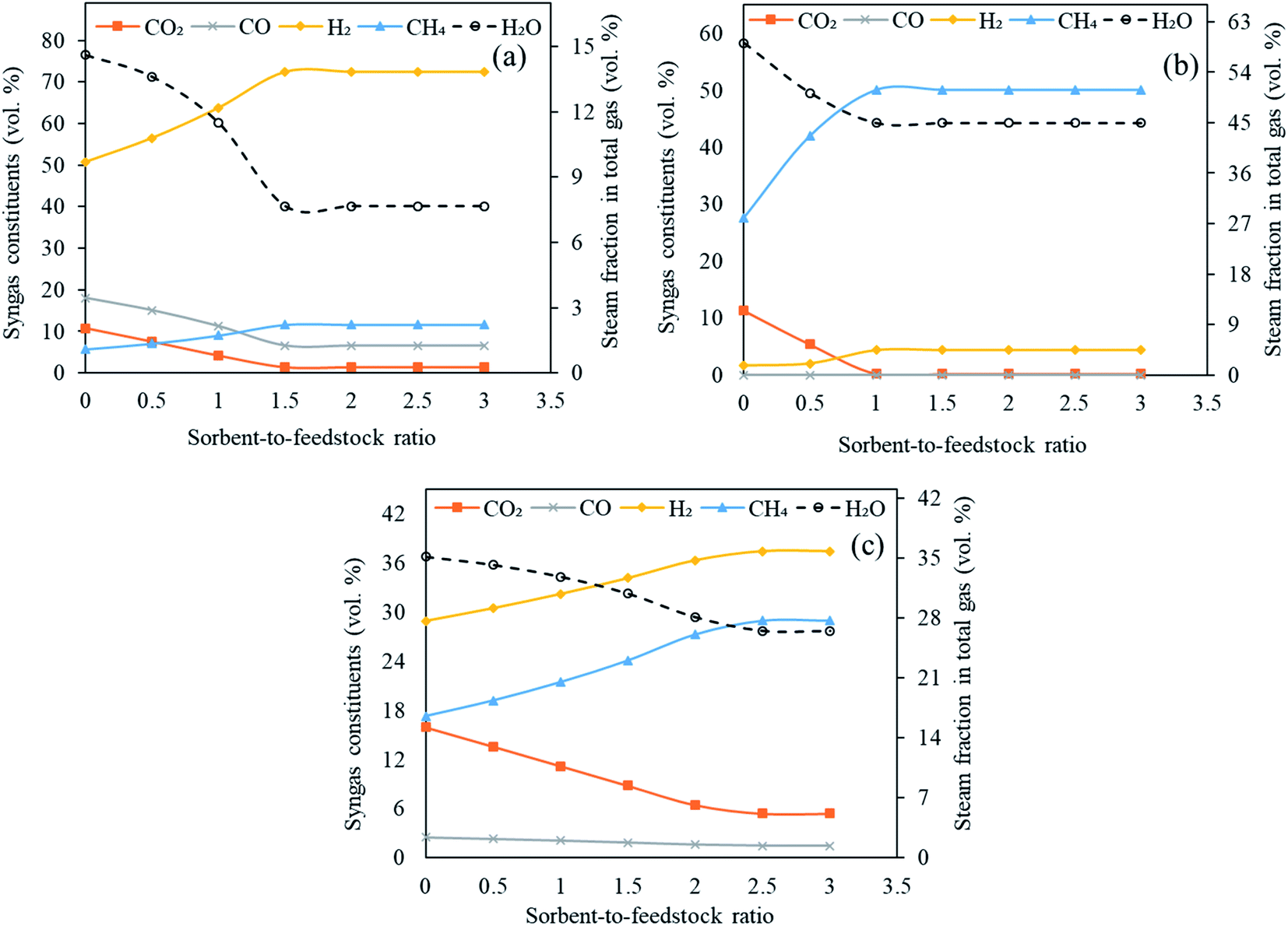 | ||
| Fig. 8 Variation in syngas constituents with variable sorbent-to-feedstock ratio (0 to 3) employing (a) CaO sorbent, (b) MgO sorbent and (c) Li4SiO4 sorbent. Note: y-axes have different ranges for each set of graphs. | ||
As evident from Table S6 of ESI,† the maximum hydrogen yield while CaO was employed as a sorbent was noted as 0.14 kg kg−1 of fuel from SOR/F of 1.5 to 3.0. In case of MgO, H2 yield increased slightly from 0.0027 kg kg−1 of fuel from SOR/F of zero to 0.0057 kg kg−1 of fuel at SOR/F of 1.0 and then remained constant till SOR/F of 3.0. On the other hand, Li based sorbent showed highest hydrogen yield (0.060 kg kg−1 of fuel) at SOR/F of 2.5 and 3.0. A decreasing trend of dry gas yields with increasing SOR/F was found. When CaO was used as a sorbent, a gas yield of 1.5 kg kg−1 of fuel was observed at zero SOR/F whereas 0.54 kg kg−1 of fuel was found at a SOR/F of 3. Similarly, as MgO and Li4SiO4 feeding were enhanced, a decline in gas yields was noticed. It was on account of CO2 adsorption with rising sorbent feeding rate which resulted in a decrease in dry gas yield. The highest LHV were seen at SOR/F of 3 for all the three sorbents (13 MJ Nm−3 with CaO, 18 MJ Nm−3 with MgO and 15 MJ Nm−3 with Li4SiO4). It was due to the improved concentrations of H2 and CH4.
4. Conclusions
In this investigation, an equilibrium modeling framework was developed using Aspen Plus (V11.0) thermodynamic environment with an objective to assess the feasibility of thermal plasma gasification coupled with CO2-sorption enhanced gasification of organic waste stream (employing RDF as model compound) using three different classes of sorbents namely, high temperature sorbents (CaO), intermediate sorbents (Li4SiO4) and low temperature sorbents (MgO) as a pathway to generate clean energy in the form of hydrogen rich syngas, capture CO2 in situ and thus, achieve carbon neutrality or negativity. The impact of gasification temperature (at Stage-I), reforming temperature (at Stage-II), steam feed rate and sorbent feed rate on hydrogen yield, dry gas yield, LHV and distribution of syngas species were evaluated and optimal operational conditions were deduced. Many unit blocks were combined and temperature dependent empirical equations were used to increase the accuracy in predictions. The modeling results were validated against the published experimental studies and they both were in good agreement. This can be considered as a model which may be employed for the use any organic waste stream/biomass using allothermal steam gasification at temperatures higher than 1000 °C in the first stage.In the proposed plasma assisted sorption enhanced gasification, the optimal CO2 sorption temperature was found to be 500 °C for CaO, 200 °C for MgO and 400 °C for Li4SiO4 with CO2 molar fractions of respectively 0.017, 0.012 and 0.669 vol%. Maximum H2 was noted to be produced at 550 °C for CaO (79 vol%), 500 °C for MgO (29 vol%) and 700 °C (55 vol%) for Li4SiO4. Optimal SOR/F ratio was found to be 1.5 for CaO, 1.0 for MgO and 2.5 for Li4SiO4. On the other hand, optimal S/F ratio with respect to H2 production were reported to be 1.4, 1.6 and 0.8 for respectively, CaO, MgO and Li4SiO4.
Future work: This study was completely a thermodynamic study. The modeling forecasts and experimental data were noted to be in good agreement qualitatively. However, in real world scenario, some reactions would not be feasible due to kinetic limitations, mostly at the lower temperatures (especially when employing MgO as a sorbent) and therefore, some amendments are necessary to improve the model predictions. The improvement in modeling deductions can be achieved by considering the reaction kinetics in the process. The aforementioned investigation is currently in progress within our lab (Lab for Plasma Chemical Technologies) and the results will soon be communicated.
Conflicts of interest
There are no conflicts to declare.Acknowledgements
This work was supported by the Ministry of Education Youth and Sports of the Czech Republic (Specific university research) [A2_FTOP_2022_015], and the Academy of Sciences of the Czech Republic [AV 21 – Efficient energy transformation and storage].References
- IPCC, Climate Change. Mitigation of Climate Change. Working Group III Contribution to the Fifth Assessment Report of the Intergovernmental Panel on Climate Change, Cambridge University Press, Cambridge, United Kingdom, New York and USA, 2014 Search PubMed.
- COP-21 Paris Agreement, European Commission, http://ec.europa.eu/clima/policies/international/negotiations/paris/index_en.htm, (accessed: December 2021).
- V. S. Sikarwar, M. Pohořelý, E. Meers, S. Skoblia, J. Moško and M. Jeremiáš, Fuel, 2021, 294, 120533 CrossRef CAS.
- B. Prabowo, M. Aziz, K. Umeki, H. Susanto, M. Yan and K. Yoshikawa, Appl. Energy, 2015, 158, 97–106 CrossRef CAS.
- G. Berndes, B. Abt, A. Asikainen, A. Cowie, V. Dale, G. Egnell, M. Lindner, L. Marelli, D. Paré and K. Pingoud, From Science to Policy, 2016, 3, 3–27 Search PubMed.
- V. S. Sikarwar, M. Hrabovský, G. Van Oost, M. Pohořelý and M. Jeremiáš, Prog. Energy Combust. Sci., 2020, 81, 100873 CrossRef.
- P. Nugent, Y. Belmabkhout, S. D. Burd, A. J. Cairns, R. Luebke, K. Forrest, T. Pham, S. Ma, B. Space and L. Wojtas, Nature, 2013, 495, 80–84 CrossRef CAS PubMed.
- N. C. Burtch, H. Jasuja and K. S. Walton, Chem. Rev., 2014, 114, 10575–10612 CrossRef CAS PubMed.
- V. S. Sikarwar, G. Ji, M. Zhao and Y. Wang, Ind. Eng. Chem. Res., 2017, 56, 5993–6001 CrossRef CAS.
- N. Florin, M. Boot-Handford and P. Fennell, 7-Calcium looping technologies for gasification and reforming, in, Calcium and Chemical Looping Technology for Power Generation and Carbon Dioxide (CO2) Capture, ed. Fennell, P., Anthony, Woodhead Publishing, 2015, pp. 139–152 Search PubMed.
- B. Li, H. Yang, L. Wei, J. Shao, X. Wang and H. Chen, Int. J. Hydrogen Energy, 2017b, 42, 4832–4839 Search PubMed.
- M. Shahbaz, S. Yusup, A. Inayat, M. Ammar, D. O. Patrick, A. Pratama and S. R. Naqvi, Energy Fuels, 2017, 31, 12350–12357 CrossRef CAS.
- C. Sreejith, C. Muraleedharan and P. Arun, Fuel Process. Technol., 2015, 130, 197–207 CrossRef CAS.
- M. E. Bretado, V. G. Velderrain, D. L. Gutiérrez, V. Collins-Martínez and A. L. Ortiz, Catal. Today, 2005, 107, 863–867 CrossRef.
- D. H. Choi, J. B. Lee, T. H. Eom, J. I. Baek, S. Jegarl and C. K. Ryu, Renewable Energy, 2013, 54, 144–149 CrossRef CAS.
- B. W. Hwang, J. H. Lim, H. J. Chae, H. J. Ryu, D. Lee, J. B. Lee, H. Kim, S. C. Lee and J. C. Kim, Process Saf. Environ. Prot., 2018, 116, 219–227 CrossRef CAS.
- G. Ji, H. Yang, M. Z. Memon, Y. Gao, B. Qu, W. Fu, G. Olguin, M. Zhao and A. Li, Appl. Energy, 2020, 267, 114874 CrossRef CAS.
- V. S. Sikarwar and M. Zhao, Bio Gasification, in, Encyclopedia of Sustainable Technologies, ed. Abraham, M.A., Elsevier, Oxford, 2017, pp. 205–216 Search PubMed.
- N. Agon, M. Hrabovský, O. Chumak, M. Hlína, V. Kopecký, A. Masláni, A. Bosmans, L. Helsen, S. Skoblja, G. Van Oost and J. Vierendeels, Waste Manage., 2016, 47, 246–255 CrossRef CAS PubMed.
- M. Jeremiáš, M. Pohořelý, K. Svoboda, S. Skoblia, Z. Beňo and M. Šyc, Appl. Energy, 2018, 217, 361–368 CrossRef.
- V. S. Sikarwar, A. Reichert, M. Pohorely, E. Meers, N. L. Ferreira and M. Jeremias, Sustainable Energy Fuels, 2021, 5, 4650–4660 RSC.
- M. Puig-Arnavat, J. C. Bruno and A. Coronas, Energy Fuels, 2012, 26, 1385–1394 CrossRef CAS.
- V. S. Sikarwar, M. Zhao, P. Clough, J. Yao, X. Zhong, M. Z. Memon, N. Shah, E. J. Anthony and P. Fennell, Energy Environ. Sci., 2016, 9, 2939–2977 RSC.
- V. S. Sikarwar, M. Zhao, P. Fennell, N. Shah and E. J. Anthony, Prog. Energy Combust. Sci., 2017, 61, 189–248 CrossRef.
- M. Hlina, M. Hrabovsky, T. Kavka and M. Konrad, Waste Manage., 2014, 34, 63–66 CrossRef CAS PubMed.
- B. Li, H. Yang, L. Wei, J. Shao, X. Wang and H. Chen, Int. J. Hydrogen Energy, 2017a, 42, 5840–5848 Search PubMed.
- W. Gao, S. Liang, R. Wang, Q. Jiang, Y. Zhang, Q. Zheng, B. Xie, C. Toe, X. Zhu, J. Wang, L. Huang, Y. Gao, Z. Wang, C. Jo, Q. Wang, L. Wang, Y. Liu, B. Louis, J. Scott, A. C. Roger, R. Amal, H. He and S. E. Park, Chem. Soc. Rev., 2020, 49, 8584–8686 RSC.
- M. R. Quddus, M. B. Chowdhury and H. I. de Lasa, Chem. Eng. J., 2015, 260, 347–356 CrossRef CAS.
- T. J. Schildhauer and S. Biollaz, Int. J. Chem., 2015, 69, 603–607 CAS.
Footnote |
| † Electronic supplementary information (ESI) available. See DOI: 10.1039/d1ra07719h |
| This journal is © The Royal Society of Chemistry 2022 |