DOI:
10.1039/D1RA08419D
(Paper)
RSC Adv., 2022,
12, 6715-6724
Low-cost Y-type zeolite/carbon porous composite from coal gasification fine slag and its application in the phenol removal from wastewater: fabrication, characterization, equilibrium, and kinetic studies†
Received
17th November 2021
, Accepted 12th February 2022
First published on 1st March 2022
Abstract
As an industrial solid waste, coal gasification fine slag (CGFS), which consists of many elements, such as silicon, aluminum, and carbon, could be used as an important resource. Therefore, this solid waste was used as a raw material to prepare high-value-added adsorption material for the treatment of industrial wastewater in this study. A hydrothermal synthesis method was applied to convert CGFS into a Y-type zeolite/carbon porous composite. The effects of time and temperature on the synthesis were studied. XRD, SEM, and other techniques were used to analyze the material and its physicochemical properties. Additionally, the adsorption performance of the material for phenol was studied. The results showed that the composite has better adsorption capacity for phenol than CGFS. The Freundlich model and pseudo-second-order kinetics well fitted the adsorption behavior of the composite, which demonstrated that the adsorption of phenol was dominated by chemical adsorption.
1. Introduction
Coal gasification is the leading technology for clean coal conversion, which can help alleviate the pressures from high energy consumption and high pollution in traditional industries.1 Among the many coal gasification technologies, entrained flow gasification technology is widely used due to its high temperature and good adaptability to coal types. Coal gasification fine slag (CGFS) is a solid waste discharged in the process of entrained flow gasification. It is produced by the filtration of some unreacted carbon due to the short residence time of coal particles in the gasifier and fly ash entering the black water system with the air flow. Therefore, besides the high content of silicon and aluminum, the CGFS also contains an amount of carbon.2
At present, the annual discharge of CGFS is about tens of millions of tons, but the main disposal method is still accumulation and landfill.3 Many CGFSs are piled in the slag yard, where it is prone to not only easily be blown away by the wind to form dust pollution in the air, but also occupies a lot of space. In addition, there are many metal elements in the slag, which can cause some pollution to the soil, reduce land utilization, and pollute groundwater.4 Therefore, the harmless treatment and resource utilization of CGFS is desired. Research in recent years has shown that CGFS has good physical and chemical properties and has good promise for application in many fields. Chen et al.5 synthesized geopolymer composites based on coal gasification fly ash, and the prepared composites could be used as construction materials in civil engineering. Dai et al.6 explored the combustibility of high carbon CGFS and found that the combustion property of CGFS was consistent with high ash coal and was suitable for pressurized furnace combustion. Zhang et al.7 prepared composite conductive materials by covering Sb–SnO2 with CGFS porous microspheres as a matrix. The results showed that the volume resistivity of the prepared materials was 2.60 × 10³ Ω cm, with excellent conductivity. Liu et al.3 used coal gasification fine slag as a raw material to prepare a mesoporous silicon material through a simple process. This material had potential application value in the field of adsorption. Miao et al.8 prepared activated carbon by CGFS. The prepared material had an interconnected macropores, mesopores, and micropores structure and high adsorption performance for CO2. Overall, CGFS is usually used as a raw material for the production of construction materials, mixed combustion material of boilers, and high-value-added materials. Among these latter types, the preparation of porous materials by CGFS can realize the high-value utilization of CGFS. However, previous reports investigated either the utilization of mineral elements or carbon. The elements in CGFS are not fully utilized. Therefore, the comprehensive utilization of carbon, silicon, and aluminum is worth studying further.
Coal chemical wastewater is an organic wastewater produced in coal chemical processes, such as coal gasification, coal liquefaction, and coal coking. As a typical industrial wastewater with high concentration, severe toxicity, and poor biodegradability,9 the composition of the wastewater is quite complex. Among the components, phenol, as a protoplasmic poison, is one of the highly toxic substances in coal chemical wastewater.10 Biological,11 catalytic,12 electrochemical,1 and physical adsorption methods13 are several basic methods for treating phenol-containing wastewater, among which adsorption is the most used method and has greater research value. Porous activated carbon and zeolite are two important materials used in the field of wastewater adsorption. Franco et al.14 prepared a novel activated carbon from fruit waste as an adsorption material, and the results showed that it had a good adsorption effect on phenol. Ektefa et al.15 explored the removal effect of phenol in water by several different types of zeolites, such as BEA, FAU, MFI, and MOR, and considered that zeolite has a uniform and nano-porous nature and has prospects in the adsorption of phenol. However, only a few reports have investigated the utilization of carbon, silicon, and aluminum in CGFS to prepare porous composites for wastewater treatment.16 Hence, it is necessary to study the preparation of cheap and available carbon and zeolite adsorption materials to effectively remove phenol from wastewater.
In this study, CGFS was used as a source of silicon, aluminum, and carbon to synthesize a Y-type zeolite/carbon porous composite by a hydrothermal synthesis. The effects of crystallization time and temperature on the synthesis of the materials were studied, and the optimum preparation conditions were obtained, and the structures of the materials were characterized in detail by various methods. At the same time, the adsorption properties of Y-type zeolite/carbon composites for phenol in wastewater under different adsorption conditions were investigated in detail and the adsorption kinetics and adsorption isotherm were analyzed to clarify the adsorption mechanism of the composites for phenol. The research aims to make waste profitable and provide an avenue for the green recycling of waste.
2. Materials and methods
2.1. Raw materials
The coal gasification fine slag (CGFS) was taken from a coal gasification company in Ningxia, China. The proximate and ultimate analyses of the CGFS are shown in Table S1.† The CGFS was dried at 105 °C for 12 h and ground, sieved with a 60–120 μm sieve, and stored in a dryer for further use.
2.2. Synthesis of the composite
Acid–base pretreatment process. The CGFS was mixed with 3 mol L−1 HCl at 80 °C for 2 h. Then, the sample was washed to neutral and dried at 105 °C for 12 h, and the acid-washed fine slag was named as HCGFS. A mixture of 4.41 g HCGFS and 1.13 g solid NaOH was ground and then placed in a tube furnace at 600 °C for 150 min. The activated product was named HCGFS-HH.
Synthesis of the Y-type zeolite/carbon composite. First, 2.54 g of NaOH and 1.00 g of NaAlO2 were dissolved in 8.55 g of deionized water. Next, 8.40 mL water glass was added to the solution and stirred for 30 min, and then the solution was aged at 28 °C for 24 h to obtain the directing agent. Afterwards, 0.47 g of NaAlO2 and HCGFS-HH were dissolved in 12.96 g of deionized water to synthesize the gel, and then 1.74 g of the directing agent was added and the mixture was stirred at 28 °C for 12 h. The sample was crystallized in the reactor at 100 °C for 36 h. After filtration, the sample was dried at 105 °C for 12 h and was named as the Y-type zeolite/carbon composite.
2.3. Samples characterization
The phase analysis of the samples was characterized by X-ray diffraction (D8 ADVANCE A25, Bruker, Germany). The porous structure of the materials was determined by a physical adsorption instrument (ASAP2460, Micromeritics, USA) with N2 as the adsorbate. The chemical structure of the carbon in materials was analyzed by a laser Raman spectrometer (DXR, Thermo Fisher, USA). The microstructure of the materials was obtained by field emission scanning electron microscopy (Regulus8100, Hitachi, Japan) and tungsten filament scanning electron microscopy (EVO18, Carl Zeiss, Germany). The framework structure of the materials was measured by Fourier transform infrared spectroscopy (Spectrum Two, PerkinElmer, American). The thermogravimetric analysis of the materials was carried out by a thermogravimetric analyzer combined with quadruple mass spectrometry (STA449F3/QMS-403, Netzsch, Germany). Solid-state 27Al and 29Si MAS NMR spectra were obtained on an AVANCE III 600 spectrometer (BRUKER, Germany). The surface charges were measured by a zeta potential analyzer (Zetasizer Nano ZS90, Malvern, UK).
2.4. Adsorption experiments
Phenol was used as a model compound in the phenol-containing wastewater to assess the adsorption capacity of the zeolite/carbon composites. The phenol solution (100 mg L−1) with 0.1 g sample was shaken by a constant temperature oscillating shaker (THZ-24-M-C, Jiangsu XingChunLan Science Instrument Co., Ltd.) at 28 °C for a certain time. Then, 2 mL of the supernatant was taken using an injector with a 0.22 μm filter membrane. The concentration of phenol was determined by 4-aminoantipyrine spectrophotometry at a maximum absorption wavelength of 510 nm using a T9 series double beam UV-Vis spectrophotometer (Beijing PURKINJE General Instrument Co., Ltd.). The effects of the initial concentrations of phenol (10–300 mg L−1), amount of sorbent (0.01–0.3 g), and initial pH (1–12) of the solution on the adsorption performance were investigated, respectively.
The calculation method for the equilibrium adsorption amount (qe, mg g−1) is shown in eqn (1), and the phenol removal ratio Re (%) was obtained by eqn (2):
| | |
Re = [(C0 − Ce)/C0] × 100
| (2) |
where
C0 (mg L
−1) and
Ce (mg L
−1) are the initial and equilibrium concentrations of solution,
V (L) is the volume of the solution, and
m (g) is the mass of the sample.
2.5. Reusability experiments
When phenol was adsorbed by the composites completely, the desorption process proceeded. The composites were soaked in HCl (1 mol L−1) and stirred for 30 min to remove the phenol. The treatment process was repeated three times and washed with deionized water to neutral. These adsorption–desorption cycles were carried out five times.
3. Results and discussions
3.1. Characteristics of CGFS, HCGFS, HCGFS-HH
The element composition analysis of CGFS before and after acid leaching is shown in Table 1, from which it could be seen that the untreated CGFS contained impurity elements such as iron, magnesium, and calcium, which would affect the crystallization and synthesis of the zeolite.17 Hydrochloric acid leaching could remove most acid-soluble mineral elements in CGFS. Compared with CGFS, the contents of iron, calcium, and magnesium in HCGFS decreased significantly, and the content of aluminum was slightly reduced, while the content of silicon increased to 77.89%.
Table 1 Element composition analyses of CGFS and HCGFS
| Sample |
Composition (wt%) |
| SiO2 |
Al2O3 |
Fe2O3 |
CaO |
Na2O |
K2O |
MgO |
Others |
| CGFS |
59.04 |
16.95 |
7.60 |
6.02 |
2.06 |
2.49 |
3.48 |
2.36 |
| HCGFS |
77.89 |
10.62 |
2.25 |
2.56 |
1.72 |
1.60 |
2.20 |
1.16 |
The XRD patterns of the materials are shown in Fig. 1. It is known that the diffraction peak of CGFS is only the weak diffraction peak of quartz, and here there were no other diffraction peaks, which indicated that CGFS had a high disorder, the amorphous material was mainly amorphous carbon and aluminosilicate, and the small amount of crystalline phase in the CGFS was mainly quartz.18 After hydrochloric acid leaching, some acid-soluble minerals were removed. According to its element composition (Table 1), it mainly consisted of amorphous aluminosilicate and carbon. After further activation by the alkali fusion of sodium hydroxide, there were obvious diffraction peaks of sodium aluminate and sodium silicate, indicating that CGFS had fully reacted with the alkali, and its structure had been obviously damaged.19
 |
| | Fig. 1 XRD patterns of the materials. | |
The SEM images of the solids is shown in Fig. S1,† from which it can be seen that the micro morphology of CGFS was a mixture of flocculent residual carbon and spherical inorganic minerals. Based on the element composition in Table 1, the inorganic minerals in CGFS were spherical particles containing silicon and aluminum, while other metal minerals were mixed with them, and fine particles were distributed on the surface of the spherical particles.20 After acid leaching, the micro morphology of HCGFS did not change significantly compared with CGFS. Owing to the removal of some acid-soluble minerals, the fine particles on the surface of the spherical particles vanished, and the surface became relatively smooth. After activation by alkali fusion, the spherical inorganic mineral particles disappeared completely and formed a mass mixture, indicating that the inorganic minerals had fully reacted with the alkali. In addition, the flaky carbonaceous fraction became more porous, which was favorable for the subsequent synthesis of porous composites.
3.2. Effect of the synthesis conditions on the composite materials
Fig. S2† exhibits the XRD patterns of the materials at different crystallization times. Also, the analysis showed that the crystallinity of the sample increased with time in a certain period. When the crystallization time was 12 h, a weak characteristic peak of the Y-type zeolite appeared at 23°, 26.7°, and 31°. As the crystallization time increased to 24 h, characteristic peaks appeared at 6°, 9.8°, and 15.4°, but the crystallinity of the product was low. When the time became 36 h, the product was highly crystalline and free of impurity peaks. Further extension of the time thereafter resulted in trans-crystallization of the product and a reduced crystallinity.
The XRD patterns of the materials with different synthesis temperatures are exhibited in Fig. S3.† It can be seen that the types of synthesized zeolite were quite different when the reaction occurred at different temperatures. When the crystallization temperature was 90 °C, the synthesized samples showed the characteristic peak of the Y-type zeolite, but the crystallinity was low. As the synthesis temperature increased to 100 °C, the obtained sample was still a Y-type zeolite, which was highly crystalline and free of spurious peaks. However, as the synthesis temperature continued to rise, the product crystalline transformation occurred and a P-type zeolite was formed. Especially when the crystallization temperature was 120 °C, the product was completely a P-type zeolite. Therefore, the optimum crystallization condition was 100 °C for 36 h. The XRD diffraction pattern of the composites synthesized under the optimum conditions was consistent with the standard card of the Y-type zeolite (PDF # 80-2463), and had fine crystallinity.
3.3. Characteristics of the composite
3.3.1. SEM analysis. Fig. 2 exhibits the SEM images of the synthesized Y-type zeolite/carbon composites, from which it can be seen that the spherical particles in CGFS disappeared completely, and its micromorphology was a flower cluster with a large number of octahedral crystals gathered on the carbonaceous matrices. During the crystallization process, the soluble aluminosilicate generated by the alkali fusion of inorganic minerals in CGFS formed silica alumina gels in aqueous solution with sodium ions and hydroxyl ions, and a large amount of the gels were deposited on the carbonaceous matrices, forming flower-cluster-like composites, and the octahedral crystal shape of the Y-type zeolite was clearly visible.21 From the EDS analysis, the main elements in the composite were oxygen, carbon, silicon, and aluminum. The mapping image shows the distribution of the different elements. It was confirmed that silicon, aluminum, and oxygen mainly existed in the composites, and each element was evenly distributed. The distribution of these three elements was consistent, which reflects the element distribution of the Y-type zeolite in the composites. The distribution of carbon was embedded in the silicon, aluminum, and oxygen. It was verified that the synthesized material was a composite of the Y-type zeolite and carbon.
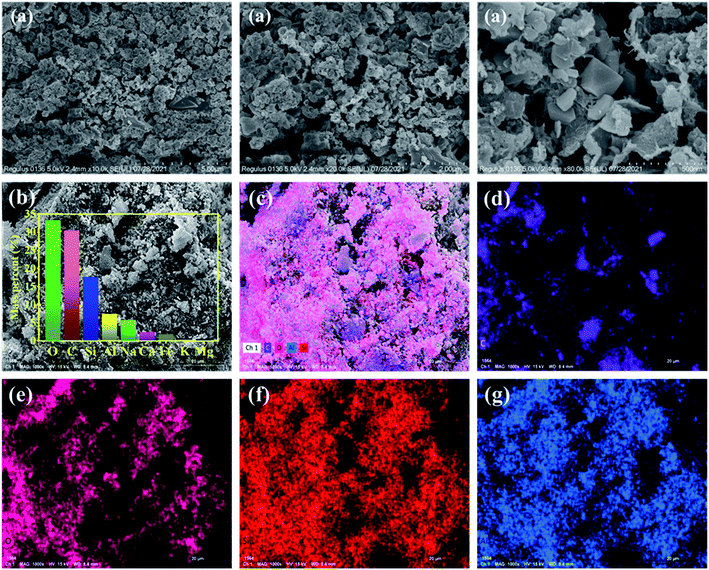 |
| | Fig. 2 SEM images (a), EDS analysis (b), SEM-EDS mapping pattern (c), and C (d), O (e), Si (f), Al (g) mapping images of the composite. | |
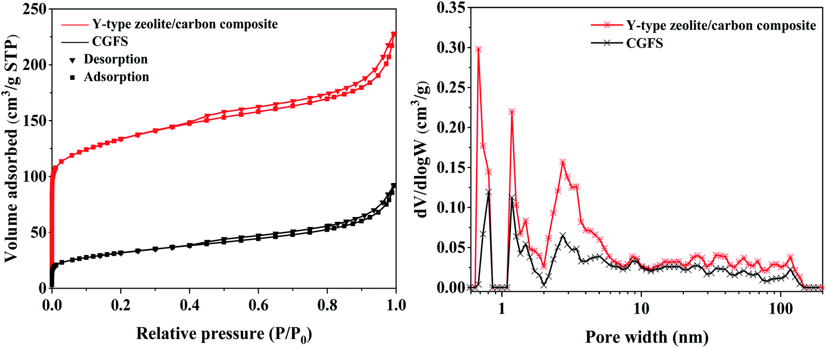
3.3.2. N2 adsorption analysis. Fig. 3 shows the N2 adsorption–desorption isotherm curves and pore-size distribution of the samples. It can be seen that around P/P0 = 0, the adsorption capacity of the composite material was much better than that of CGFS, indicating that there were more microporous structures in the synthesized composites. With the increase in relative pressure, the adsorption and desorption curve showed a slow upward trend, which was a combination of type I curve and type IV curve, proving that the sample had a porous structure.22 When the P/P0 was in the range of 0.4–1.0, an H4 type hysteresis loop curve appeared, which proved that the sample contained mesopores.23 Meanwhile, it could be clearly seen from the pore-size distribution that the composite had a hierarchical pore structure of micropores (0.72 and 1–2 nm) and mesopores (2–10 nm). It could be seen from Table S2† that compared with CGFS, the Y-type zeolite composite had a more abundant porous structure, and the SBET of the composite increased from 111.09 m2 g−1 to 439.68 m2 g−1, and the Vtotal increased from 0.14 cm3 g−1 to 0.35 cm3 g−1.
 |
| | Fig. 3 N2 adsorption–desorption isotherm and pore-size distribution of the samples. | |
3.3.3. FT-IR analysis. The FT-IR spectra of the samples are shown in Fig. S4.† The vibration peaks near 3500 cm−1 belong to the O–H vibration peaks in the skeleton of Y-type zeolite, while the vibration peaks near 1640 cm−1 were caused by the shear vibration of H protons in the lattice water molecules. The vibration peaks around 1050 and 730 cm−1 were ascribed to the asymmetric and symmetric stretching inside the TO4 (T = Si, Al) tetrahedra.24 The vibrational peaks near 580 cm−1 were the characteristic peaks of the double six-membered ring (D6R) of the Y-type zeolite. The presence of these characteristic peaks proved that the synthesized sample had an FAU-type zeolite skeleton structure.25
3.3.4. Raman analysis. Fig. S5† shows the Raman spectra of the samples. In general, there were two distinctive peaks in the first order region (2000–800 cm−1) of the Raman spectra of the carbonaceous materials, which were the D band and the G band, respectively.26 The relative intensity of the D peak in the range of 1470–782 cm−1 reflected the disorder of the crystalline carbon structure, and the G peak in the range of 1959–1470 cm−1 corresponded to the vibrational mode (E2g symmetry) of an ideal graphite lattice.27 The integrated area ratio of the peaks is often used as a parameter of the structural change of the sample, and the ratio of ID to IG is used to quantitatively describe the degree of ordering of the carbon structure of the sample, whereby the lower the ratio, the higher the degree of ordering.28 The peak fitting results of the curves showed ID/IG of 1.652 and 1.464 for the raw material and composite, respectively, which indicated that the carbon structure in CGFS was less ordered and had a more amorphous carbon structure.
3.3.5. Thermogravimetric analysis. The TG and DTG curves of CGFS and the composite are exhibited in Fig. S6,† and the results indicated that there were two stages of weight loss in the Y-type zeolite/carbon composite compared to CGFS.29 The first stage was related to the moisture loss. The dehydration rate of the composite was faster between 100–200 °C, which mainly removed the free water from the zeolite, and the dehydration rate decreased after 200 °C. The second stage was related to the loss of carbon in the sample, which led to mass loss due to the release of CO and CO2 from the combustion of carbon at 500–600 °C.30 After 700 °C, there was basically no change in weight.
3.3.6. 29Si and 27Al NMR analysis. The solid-state nuclear magnetic resonance (NMR) technique can provide an effective method for analyzing the framework structure of materials. Fig. 4 depicts the 29Si MAS NMR and 27Al MAS NMR of the samples. The 29Si MAS NMR of CGFS had a signal ranging from −70 to −130 ppm, which demonstrated its heterogeneous and glassy nature. For the Y-type zeolite/carbon composite, five obvious narrow peaks appeared at −84, −89, −93, −97, and −101 ppm, corresponding to Si (4Al), Si (3Al), Si (2Al), Si (1Al), and Si (0Al), respectively.31 The 27Al MAS NMR spectra of the CGFS showed a broad diffraction peak from 80 to 30 ppm, which also indicated the disorder and heterogeneity of the aluminum species in CGFS. The 27Al MAS NMR peak of the composite moved to 64 ppm and became strong and sharp, indicating that the aluminum in the composite existed as four coordination skeleton aluminum. These also proved the formation of the Y-type zeolite.32
 |
| | Fig. 4 29Si NMR (a) and 27Al NMR (b) of samples. | |
3.4. Effect of different conditions on the adsorption performance of the samples for phenol
The adsorption performance of the sample for phenol versus time are shown in Fig. 5a. The curve shows that the qt value increased rapidly in the first 30 min, which means that the adsorption proceeded rapidly in the early stage. Then, qt reached a stable value at about 60 min, indicating that the adsorbed molecules occupied all the vacant active space of the adsorbent. When the adsorption time was 120 min, the adsorption capacity of phenol reached saturation. In addition, when the Y-type zeolite/carbon composite reached adsorption equilibrium, the adsorption rate of CGFS was only 32.8%, while the adsorption rate of the Y-type zeolite/carbon composite was 50%, because compared with CGFS, the Y-type zeolite/carbon composite had a larger specific surface area, and more surface groups and active centers, resulting in a better adsorption effect.
 |
| | Fig. 5 Effect of the adsorption time (a), zeta potential (b), pH (c), initial phenol concentration (d) and the amount of adsorbent (e) on adsorption. | |
The pH of the phenol in wastewater can seriously affect the adsorption process. The pH value affects the chemical properties of the solution itself, the surface charge of the sample, and the degree of ionization of phenol.33 The zeta potential reflects the strength of attraction or repulsion between an adsorbent and adsorbate.34 Fig. 5b shows the charge of zeta potential of CGFS and the composite. As the solution became more alkaline, the zeta potential gradually decreased. Fig. 5c illustrates the effect of phenol adsorption capacity with the pH of the solution (pH 1–12). It can be seen from the results that the qt as well as the adsorption rate decreased gradually with increasing the pH, and when the solution became alkaline, the adsorption capacity decreased rapidly, and reached its optimum at pH 7. Such results suggest that phenol will be better adsorbed under acidic or neutral conditions compared to alkaline solutions. The possible reason for this is that phenol exists mainly in the molecular state in acidic or neutral solutions, which allows better contact with the adsorbent, while in alkaline solutions, phenol exists in the form of the phenol root ion (C6H5O−), which has an inhibitory effect on the adsorption process by repelling each other with the negative charge on the zeolite surface.35 Meanwhile, for CGFS, the smaller effect of phenol pH on the adsorption effect was attributed to the smaller specific surface area and fewer active sites of CGFS, which has a limited capacity for phenol adsorption.
Fig. 5d exposes the effect of the initial concentration of the phenol solution (10–300 mg L−1) on the adsorption effect. When the concentration was 10 mg L−1, the adsorption rate of the composite reached 99%. As the initial concentration increased, the adsorption rate gradually decreased and was only 34% at an initial concentration of 300 mg L−1; and this pattern was also observed for CGFS. This is because when the initial concentration is low, the number of adsorbed phenol molecules is lower than the number of adsorption sites on the adsorbent surface, which results in a high adsorption rate. However, as the concentration increases, eventually the number of phenol molecules in the bulk phase far exceeds the number of active sites on the adsorbent surface, which leads to a serious shortage of adsorption sites and the adsorption rate decreases significantly. In addition, it can be seen from the adsorption rate curve that the adsorption rate gradually decreased when the initial concentration was greater than 100 mg L−1, but the decrease was not obvious, so 100 mg L−1 was chosen as the experimental concentration.
The effects of different adsorbent doses (0.01–0.3 g) on the adsorption effect were studied, and the results are shown in Fig. 5e. It could be found that when the mass of solid changed from 0.01 g to 0.1 g, the adsorption rate changed from 5.3% to 53.5% with the Y-type zeolite/carbon composite as the adsorbent and from 4.0% to 37.1% with CGFS as the adsorbent. However, when the mass of solid was higher than 0.1 g, the increase in phenol adsorption rate tapered off. The quantity of adsorption sites increased with the increase in the solid, and the adsorption rate increased rapidly at the beginning stage. After reaching a certain limit, the increase in the adsorbent dosage would lead to the aggregation of the adsorbent, which will result in the decrease of adsorption sites, thus the adsorption rate increased slowly.
3.5. Adsorption kinetics study
Fitting the calculation of the adsorption kinetics can allow an insight into the adsorption mechanism of phenol on the samples. A pseudo-first-order kinetic model (eqn (3)) and pseudo-second-order kinetic model (eqn (4)) are generally used to fit the adsorption process.36| |
ln(qe − qt) = ln![[thin space (1/6-em)]](https://www.rsc.org/images/entities/char_2009.gif) qe − k1t qe − k1t
| (3) |
| |
 | (4) |
where, k1 (h−1) and k2 (g mg−1 min−1) are the diffusion rate constants of the two models, respectively, and qt (mg g−1) is the adsorption amount at time t (min).
Fig. 6 and Table 2 show the fitting curves and calculation results, respectively. Based on the calculated results, the results proved that the pseudo-first-order kinetic model was not applicable to the adsorption process of both materials because of the low R2 values (0.365 and 0.869) and the small calculated qe values (1.62 and 6.64 mg g−1). In comparison, under the pseudo-second-order kinetic model, the R2 values for both materials were relatively high (0.995 and 0.998) and the calculated qe values (8.36 and 12.45 mg g−1) were close to the experimental qe values (8.7 and 13 mg g−1). These data prove that the adsorption processes followed a pseudo-second-order kinetic model, which proved that the adsorption process was controlled by a chemisorption mechanism that involved adsorption steps, such as surface adsorption and liquid film diffusion.37 In addition, the k value of the Y-type zeolite/carbon composite was larger, indicating that the Y-type zeolite/carbon composite had a larger SBET and Vtotal, which was conducive to the diffusion of the adsorbent. This result is consistent with the previous characterization findings.
 |
| | Fig. 6 The pseudo-first-order (a) and pseudo-second-order plots (b) for phenol adsorption on the samples. | |
Table 2 Parameters of the adsorption kinetics
| Adsorbents |
Pseudo first order |
Pseudo second order |
| qe(exp) (mg g−1) |
qe(cal) (mg g−1) |
k1 (min−1) |
R2 |
qe(cal) (mg g−1) |
k2 (min−1) |
R2 |
| CGFS |
8.70 |
1.62 |
0.019 |
0.365 |
8.36 |
0.105 |
0.995 |
| Y-type zeolite/carbon composite |
13.00 |
6.64 |
0.021 |
0.869 |
12.45 |
0.265 |
0.998 |
3.6. Adsorption isotherms analysis
It is important to study the surface properties and affinity of the adsorbent as well as the interaction between the adsorbent and the adsorbate.38 Therefore, adsorption isotherm studies were carried out under optimum adsorption conditions. Currently, the most commonly used adsorption isotherm models are the Langmuir isotherm model (eqn (5)) and the Freundlich isotherm model (eqn (6)), and so these two models were used to fit the adsorption process.39| |
 | (5) |
| |
 | (6) |
where, kF [(mg g−1) (L mg−1)1/n] is the Freundlich constant, qmax (mg g−1) is the maximum adsorption amount, and kL (L mg−1) is the Langmuir constant.
Fig. S7† shows the fitting of the adsorption process for the samples and the calculated data are listed in Table 3. From these data, it can see that the R2 obtained by fitting the Freundlich isotherm model was close to 0.999, which indicated that the process of phenol adsorption on both adsorbents could be represented by the Freundlich isotherm model, and it was thus clear that the surface adsorption of phenol on the adsorbent was non-uniform multilayer adsorption. Meanwhile, in the Freundlich equation, the n value responds to the difficulty of adsorption, and 1/n < 1 in Table 3 indicates that n > 1, which proved that the adsorbent had good adsorption capacity for phenol.40
Table 3 Parameters of the adsorption isotherm
| Adsorbents |
Freundlich |
Langmuir |
| KF (mg g−1)·(L mg−1)1/n |
1/n |
R2 |
qmax (mg g−1) |
KL (L mg−1) |
R2 |
| CGFS |
0.255 |
0.997 |
0.986 |
26.320 |
−0.001 |
0.968 |
| Y-type zeolite/carbon composite |
0.258 |
0.951 |
0.999 |
47.620 |
0.002 |
0.971 |
In the literature, several studies have addressed the removal of phenol using different kinds of adsorbents. Compared with most adsorbents, the composite had good adsorption performance, as shown in Table 4. Comprehensive analysis of the adsorption performance and preparation cost of the adsorbent showed that the composite in this work has potential as a material for removing phenol from wastewater.
Table 4 Literature results of the adsorption of phenol by different adsorbents
| Adsorbents |
qmax (mg g−1) |
References |
| Y-type zeolite/carbon composite |
47.62 |
This work |
| HFAU (5) |
13.61 |
Chaouati et al.41 |
| HFAU (60) |
24.51 |
Chaouati et al.41 |
| Ni–NaY zeolite |
89.20 |
Mohammed et al.42 |
| Natural clays |
10.00 |
Dehmani et al.43 |
| Porous carbon nanospheres aerogel |
104.20 |
Zhang et al.44 |
| High-silica zeolite |
5.00 |
Jiang et al.45 |
| Magnetic poly(ethylene glycol dimethacrylate-n-vinylimidazole) |
33.83 |
Özdemir et al.46 |
| Fe3O4@SiO2 |
44.7 |
Yang et al.47 |
3.7. Reusability experiments study
In order to better reduce the industrial application cost of adsorbents, the reusability performance of an adsorbent is very important, and the results are shown in Fig. 7. It can be seen from the results that after 5 cycles, the adsorption rate decreased from 53% to 47%, which still exhibited good reusability. This might be mainly because HCl could increase the polarity of the solvent and promote the solubility of phenol. However, the eluent did not completely desorb phenol, and some molecules still existed in the pores, resulting in a lower adsorption rate when cyclic adsorption was performed compared to the previous one.
 |
| | Fig. 7 Influence of the regeneration performance of the composite. | |
4. Conclusion
In order to realize the harmless and resource utilization of CGFS, Y-type zeolite/carbon porous composites were synthesized from CGFS. The structural characteristics of the Y-type zeolite/carbon composites were studied, and their removal effect and adsorption mode for phenol in solution were discussed. This study achieved the goal of converting waste into valuable materials and disposing waste with waste. The main findings are as follows:
(1) Taking advantage of the rich content of silicon aluminum inorganic mineral and residual carbon in CGFS as a source of silicon, aluminum, and carbon, a Y-type zeolite/carbon composite was prepared by means of a simple acid treatment, alkali activation, and hydrothermal synthesis. The octahedral crystalline Y-type zeolite aggregated around the flaky and porous carbonaceous materials to form porous composites with a large specific surface area (439.68 m2 g−1), ensuring that the composite could be used as a good adsorbent.
(2) The optimum adsorption conditions were measured as follows: solution pH, 7; adsorbent addition, 0.1 g; initial concentration of phenol solution, 100 mg L; and resistance time, 120 min. Compared with CGFS, the Y-type zeolite/carbon composites had a better adsorption effect on phenol. The pseudo-second-order kinetic model reflected the kinetic mechanism of the adsorption process, which was controlled by a chemisorption mechanism. The adsorption isotherm fitting results showed that the Freundlich isotherm model better explained the mechanism between the adsorbent and the adsorbate, and reflected that the surface adsorption of phenol on the porous composite involved non-uniform multilayer adsorption.
Author contributions
Zhen Chai: investigation, data curation, conceptualization, writing – original draft preparation. Peng Lv: validation, project administration. Yonghui Bai: methodology, validation, writing – reviewing and editing. Jiaofei Wang: supervision, software. Xudong Song: supervision, visualization. Weiguang Su: supervision, visualization. Guangsuo Yu: investigation, supervision.
Conflicts of interest
There are no conflicts to declare.
Acknowledgements
The authors gratefully acknowledge the financial support from the Project of Key Research Plan of Ningxia (No. 2021BEE03011) and Key Program of Yinchuan Science and Technology Bureau (No. 2021ZD08).
References
- B. Hou, H. Han, H. Zhuang, P. Xu, S. Jia and K. Li, Bioresour. Technol., 2015, 196, 721–725 CrossRef CAS PubMed.
- Y. Tang, X. Guo, Q. Xie, R. B. Finkelman, S. Han, B. Huan and X. Pan, Energy Fuels, 2018, 32, 3052–3067 CrossRef CAS.
- S. Liu, X. Chen, W. Ai and C. Wei, J. Cleaner Prod., 2019, 212, 1062–1071 CrossRef CAS.
- S. Wu, S. Huang, Y. Wu and J. Gao, J. Energy Inst., 2015, 88, 93–103 CrossRef CAS.
- Y. Chen, X. Zhou, S. Wan, R. Zheng, J. Tong, H. Hou and T. Wang, Constr. Build. Mater., 2019, 211, 646–658 CrossRef CAS.
- G. Dai, S. Zheng, X. Wang, Y. Bai, Y. Dong, J. Du, X. Sun and H. Tan, J. Environ. Manage., 2020, 271, 111009 CrossRef CAS PubMed.
- J. Zhang, J. Zuo, Y. Jiang, A. Ju, D. Zhu, J. Zhang and C. Wei, Powder Technol., 2021, 385, 409–417 CrossRef CAS.
- Z. Miao, Z. Guo, G. Qiu, Y. Zhang and J. Wu, J. CO2 Util., 2021, 50, 101585 CrossRef CAS.
- Y. Suo and Y. Ren, Chem. Eng. Sci., 2021, 245, 116810 CrossRef CAS.
- S. Jia, H. Han, B. Hou, H. Zhuang, F. Fang and Q. Zhao, Chemosphere, 2014, 117, 753–759 CrossRef CAS PubMed.
- S. T. Tay, B. Y. Moy, A. M. Maszenan and J. Tay, Appl. Microbiol. Biotechnol., 2005, 67, 708–713 CrossRef CAS PubMed.
- H. Zhuang, H. Han, B. Hou, S. Jia and Q. Zhao, Bioresour. Technol., 2014, 166, 178–186 CrossRef CAS PubMed.
- X. Guo, J. Wang, Y. Wang and J. Zhang, Procedia Environ. Sci., 2012, 12, 152–158 CrossRef.
- D. S. P. Franco, J. Georgin, M. S. Netto, D. Allasia, M. L. S. Oliveira, E. L. Foletto and G. L. Dotto, J. Environ. Chem. Eng., 2021, 9, 105927 CrossRef CAS.
- F. Ektefa, S. Javadian and M. Rahmati, J. Taiwan Inst. Chem. Eng., 2018, 88, 104–113 CrossRef CAS.
- N. Yuan, A. Zhao, Z. Hu, K. Tan and J. Zhang, Chemosphere, 2022, 287, 132227 CrossRef CAS PubMed.
- Y. Lee, J. T. Soe, S. Zhang, J. Ahn, M. B. Park and W. Ahn, Chem. Eng. J., 2017, 317, 821–843 CrossRef CAS.
- A. Gęsikiewicz-Puchalska, M. Zgrzebnicki, B. Michalkiewicz, U. Narkiewicz, A. W. Morawski and R. J. Wrobel, Chem. Eng. J., 2017, 309, 159–171 CrossRef.
- J. Lladó, M. Solé-Sardans, C. Lao-Luque, E. Fuente and B. Ruiz, Process Saf. Environ. Prot., 2016, 104, 294–303 CrossRef.
- Y. Zhao, W. U. Haijun, X. Zhang, H. Liu, Y. Jing and W. Yuan, Clean Coal Technology, 2016, 22, 7–11 CrossRef.
- T. Le, Q. Wang, B. Pan, A. V. Ravindra, S. Ju and J. Peng, Microporous Mesoporous Mater., 2019, 284, 476–485 CrossRef CAS.
- A. Centineo and S. Brandani, Chem. Eng. Sci., 2020, 214, 115417 CrossRef CAS.
- K. P. De Jong, J. Zečević, H. Friedrich, P. E. De Jongh, M. Bulut, S. Van Donk, R. Kenmogne, A. Finiels, V. Hulea and F. Fajula, Angew. Chem., Int. Ed., 2010, 49, 10074–10078 CrossRef CAS PubMed.
- S. Oruji, R. Khoshbin and R. Karimzadeh, Mater. Chem. Phys., 2019, 230, 131–144 CrossRef CAS.
- N. Ndlovu, R. Missengue, L. F. Petrik and T. Ojumu, J. Environ. Eng., 2017, 143, 04017042 CrossRef.
- P. Veerakumar, I. P. Muthuselvam, C. T. Hung, K. C. Lin, S. B. Liu and F. C. Chou, ACS Sustainable Chem. Eng., 2016, 6772–6782 CrossRef CAS.
- D. Kumbhar, A. Palliyarayil, D. Reghu, D. Shrungar, S. Umapathy and S. Sil, Carbon, 2021, 178, 792–802 CrossRef CAS.
- M. C. Sforna, M. V. Zuilen and P. Philippot, Geochim. Cosmochim. Acta, 2014, 124, 18–33 CrossRef CAS.
- S. S. Bukhari, S. Rohani and H. Kazemian, Ultrason. Sonochem., 2016, 28, 47–53 CrossRef CAS PubMed.
- J. Wu, B. Wang and F. Cheng, J. Therm. Anal. Calorim., 2017, 129, 1899–1909 CrossRef CAS.
- D. H. Brouwer, C. C. Brouwer, S. Mesa, C. A. Semelhago, E. E. Steckley, M. P. Y. Sun, J. G. Mikolajewski and C. Baerlocher, Microporous Mesoporous Mater., 2020, 297, 110000 CrossRef CAS.
- S. Su, H. Ma and X. Chuan, Adv. Powder Technol., 2016, 27, 139–144 CrossRef CAS.
- N. Tahir, H. N. Bhatti, M. Iqbal and S. Noreen, Int. J. Biol. Macromol., 2017, 94, 210–220 CrossRef CAS PubMed.
- J. Dickson, N. A. Conroy, Y. Xie, B. A. Powell, J. C. Seaman, M. I. Boyanov, K. M. Kemner and D. I. Kaplan, Chem. Eng. J., 2020, 402, 126268 CrossRef CAS.
- X. Wang, A. Chen, B. Chen and L. Wang, Ecotoxicol. Environ. Saf., 2020, 204, 111093 CrossRef CAS PubMed.
- J. Simonin, Chem. Eng. J., 2016, 300, 254–263 CrossRef CAS.
- J. Wang and X. Guo, J. Hazard. Mater., 2020, 390, 122156 CrossRef CAS PubMed.
- E. C. Nnadozie and P. A. Ajibade, Data Brief, 2020, 32, 106292 CrossRef PubMed.
- A. Arabpour, S. Dan and H. Hashemipour, Arabian J. Chem., 2021, 14, 103003 CrossRef CAS.
- L. N. Rozanov, Vacuum, 2021, 189, 110267 CrossRef CAS.
- N. Chaouati, A. Soualah and M. Chater, C. R. Chim., 2013, 16, 222–228 CrossRef CAS.
- B. Ba Mohammed, K. Yamni, N. Tijani, H. Lee, Y. Dehmani, H. El Hamdani, A. A. Alrashdi, S. Ramola, T. Belwal and H. Lgaz, J. Saudi Chem. Soc., 2021, 25, 101224 CrossRef CAS.
- Y. Dehmani, O. E. Khalki, H. Mezougane and S. Abouarnadasse, Chem. Data Collect., 2021, 33, 100674 CrossRef CAS.
- J. Zhang, L. Qin, Y. Yang and X. Liu, Sep. Purif. Technol., 2021, 274, 119029 CrossRef CAS.
- N. Jiang, R. Shang, S. G. J. Heijman and L. C. Rietveld, Sep. Purif. Technol., 2020, 235, 116152 CrossRef CAS.
- İ. Özdemir, N. Tekin and A. Kara, J. Macromol. Sci., Part A: Pure Appl.Chem., 2019, 56, 564–576 CrossRef.
- W. Yang, L. Liu, X. Ni, W. Huang, H. Liu and W. Xu, J. Sep. Sci., 2016, 39, 503–517 CrossRef CAS PubMed.
Footnote |
| † Electronic supplementary information (ESI) available. See DOI: 10.1039/d1ra08419d |
|
| This journal is © The Royal Society of Chemistry 2022 |
Click here to see how this site uses Cookies. View our privacy policy here. 
 Open Access Article
 This Open Access Article is licensed under a Creative Commons Attribution-Non Commercial 3.0 Unported Licence
 *a,
Jiaofei Wanga,
Xudong Songa,
Weiguang Sua and
Guangsuo Yuab
*a,
Jiaofei Wanga,
Xudong Songa,
Weiguang Sua and
Guangsuo Yuab