 Open Access Article
Preparation of poly(ionic liquid)/multi-walled carbon nanotube fillers using divinylbenzene as a linker to enhance the impact resistance of polyurethane elastomers
Zehui Xiangab,
Fan Huab,
Xueyan Wuab,
Fugang Qi *ab,
Biao Zhang
 *ab,
Nie Zhaoab and
Xiaoping Ouyangab
aSchool of Materials Science and Engineering, Xiangtan University, Xiangtan, 411105, P. R. China. E-mail: qifugang@xtu.edu.cn
bKey Laboratory of Low Dimensional Materials and Application Technology of Ministry of Education, Xiangtan University, Xiangtan 411105, P. R. China
First published on 12th January 2022
Abstract
The brittle fracture of polyurethane elastomer (PUE) under high-speed impact limits its application in high-speed impact protection. Here, based on the principle of free radical polymerization and π–π conjugation, composite nanoparticles (C-MWCNTs) are prepared by copolymerization of epoxy group ionic liquid (GVIMBr) and divinylbenzene (DVB) on MWCNTs using DVB as a linker. C-MWCNTs participate in the curing process of PUE through epoxy groups to form in situ crosslinked C-MWCNTs/PUE, which improves the energy absorption and high-speed impact properties of PUE. Compared with neat PUE, the maximum compressive strength and energy absorbed by C-MWCNTs/PUE are increased by 46.3% and 23.6%, respectively. By observing the microsurface and fracture morphology of C-MWCNTs/PUE, the relationship between macroscopic mechanical properties and microstructure is constructed. The improvement of the mechanical properties of the C-MWCNTs/PUE is attributed to the interfacial interaction and homogeneous dispersion of the C-MWCNTs in the PUE matrix. These microscopic effects are caused by the good compatibility between GVIMBr and PUE matrix and the synergistic enhancement between GVIMBr and MWCNTs.
1. Introduction
As the demand for impact protection is unprecedentedly increasing, the interest in polymer elastomer that can effectively block accompanying external impact is also constantly increasing.1–3 Polyurethane elastomer (PUE) is one of the highly attractive high-performance polymers. Due to its impressive toughness, easy processability and competitive price, it exhibits tremendous application value and market potential as a new generation of impact protection materials.4–6 Nevertheless, the intrinsic suppleness of PUE makes it very sensitive to impact loading, and its high-speed impact resistance, scratch resistance and rigidity are poor. So far, researchers have also studied different methods to further improve these mechanical and physical properties. Nanofiller reinforcement, as an effective and simple method, is worthy of in-depth study.3,7,8Multi-walled carbon nanotubes (MWCNTs) have been the most popular nanomaterials in recent years. Its unique structure endows them with excellent electrical, heat conduction and mechanical properties, which has attracted wide attention in different fields.9–11 However, MWCNTs have poor compatibility with polymers due to their high specific surface energy and strong interior interactions.12 Normally, the methods to solve the problem of MWCNTs aggregation can be divided into two parts: covalent methods and noncovalent methods.13 For the covalent ways, the strong oxidation of acids and alkali will destroy the graphite structure of MWCNTs, resulting in a decrease in mechanical properties. Instead, the non-covalent modification of MWCNTs is a simple and mild method, but it will introduce troublesome and tricky post-treatment process.
However, these drawbacks can be avoided by using ionic liquids (ILs).14,15 ILs, as liquid salts at room temperature, have recently emerged as “designer solvents” and have been applied in organic synthesis, analytical chemistry and lubrication, etc.16,17 In particular, imidazolium based ILs modified MWCNTs can effectively avoid agglomeration.18 Moreover, ILs can also play a role in bonding between MWCNTs and the polymer matrix, providing a tighter interface interaction, so that the composite polymer has higher toughness and strength. Based on the above reasons, the interaction of imidazolium ILs with MWCNTs (ILs@MWCNTs) has been tactically applied to the synthesis of functional nanomaterials. Among them, due to their tunable physicochemical properties,19 outstanding solubility and miscibility,20 mechanical strength and impact resistance,21,22 ILs@MWCNTs have successfully enhanced different properties (toughness, thermal stability, dispersibility, compatibility, etc.) of various polymers (polyurethane,23 epoxy24 and hydrogenated nitrile elastomer,25 etc.). However, if ILs are used to directly coat MWCNTs noncovalently, due to the instability of π–π conjugations between imidazole rings and MWCNTs, MWCNTs will not have very stable dispersion in water or organic solvents. This will seriously affect the improvement of the mechanical properties of the polymer.26 To solve this problem, choosing a suitable crosslinking agent as a bridge between ILs and MWCNTs seems to be an effective method. As a cross-linking agent, divinylbenzene (DVB) is easily adsorbed on the surface of MWCNTs due to its unique and stable π–π conjugated structure. However, it cannot be ignored that the compatibility of DVB with polymeric substrates is not ideal. Therefore, by choosing a suitable initiator to attack the surface of DVB and ionic liquids containing double bonds, a dense bilayer co-coated MWCNTs material can be formed by a free radical polymerization reaction. The material can be stably and uniformly dispersed in the polymer.
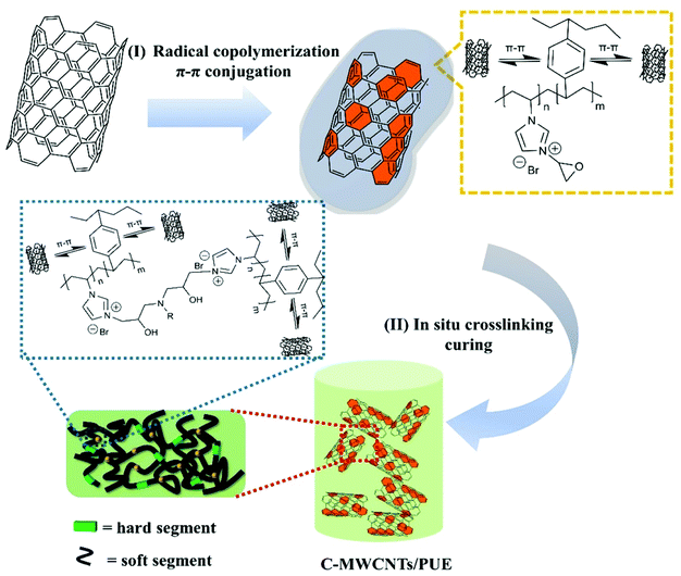
In this paper, a vinyl imidazole ionic liquid containing epoxy groups is prepared, and DVB is used as a cross-linking agent. By free radical polymerization, 1-epoxy-3-vinylimidazole and DVB are copolymerized to coat MWCNTs to form hybrid nanoparticles (C-MWCNTs) with a coating structure. More importantly, the epoxy groups on the hybrid nanoparticles participate in the curing reaction of PUE, which improves the compatibility and dispersibility of MWCNTs in PUE (the preparation process is shown in Fig. 1). The mechanical test results show that the addition of a small amount (1.0 wt%) of C-MWCNTs hybrid nanoparticles greatly improves the compressive strength and impact strength of C-MWCNTs/PUE. In addition, the ultra-depth of field three-dimensional system and scanning electron microscope (SEM) were used to observe the neat PUE and C-MWCNTs/PUE. C-MWCNTs construct an excellent organic–inorganic interface in PUE and achieve stable and uniform dispersion, which is an important reason for the improvement of the mechanical properties of PUE. In general, this work provides a simple new strategy for the non-covalent modification of MWCNTs and uses it in the application of PUE impact protection, so that PUE can be more widely used in the field of impact protection.
2. Experimental
2.1. Materials
A component toluene diisocyanate prepolymer (2,4-TDI, –NCO, 6.212 wt%) and B component (poly(oxycarbonyloxy-1,6-hexanediyl), Terathane (R) 1400, dibutyl tin dilaurate, triethylamine, and JEFFLINK™ 754 chain extender, –OH, 6.358 wt%) were supplied by Qingdao Green World New Material Technology Co., Ltd. Other related raw materials including multi-walled carbon nanotubes (MWCNTs, ≥95%, ID: 5–12 nm, OD: 30–50 nm, length: 10–20 μm), methylbenzene (C7H8, AR, 99.5%), 1-vinylimidazole (C5H6N2, 99%), epoxy bromopropane (C3H5BrO, 98%), divinyl benzene (DVB, 55%, containing 1000 ppm TBC stabilizer), 2,2′-azobis(2-methylpropionitrile) (AIBN, 99%, recrystallization), reagents were purchased from Shanghai Macklin Biochemical Technology Co., Ltd.2.2. Synthesis of 1-epoxy-3-vinylimidazole bromide salt (GVIMBr)
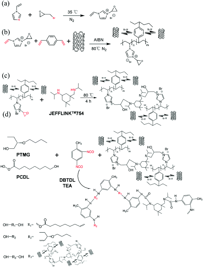
The synthetic chemical formula of GVIMBr was shown in Fig. 2a epoxy bromopropane (2.29 g) and 1-vinylimidazole (2.82 g) were loaded in a three necked flask. The mixture was stirred in N2 atmosphere and reacted at 35 °C for 24 h. After washing with acetone for several times, the reaction products were vacuum dried for 24 h at 100 °C to finally obtain the product GVIMBr.272.3. Synthesis of C-MWCNTs composite nanoparticles
GVIMBr and DVB co-encapsulated MWCNTs were prepared by radical polymerization and π–π conjugation (Fig. 2b). MWCNTs (0.2 g) and DVB (0.26 g) methylbenzene (20 ml) were loaded in a three necked flask. A constant pressure drip funnel (containing a mixed solution of 0.05 g AIBN and 10 ml methylbenzene) was placed on the left side of the three-necked flask. Next, the mixture was stirred in N2 atmosphere and condensation reflux reacted at 80 °C for 30 min. Then, GVIMBr (0.43 g) was added to a three-necked flask to continue the reaction. After the reaction, the product C-MWCNTs were filtered, washed and vacuum dried at 100 °C for 24 h.2.4. Preparation of C-MWCNTs/PUE composite materials
The chemical formula for the preparation of C-MWCNTs/PUE is shown in Fig. 2c and d. C-MWCNTs were added to component B proportionally and stirred evenly at 80 °C for 4 h. Then, component A was added to the mixture, stirred evenly and poured into the mold for curing and molding. The schematic diagram of the fully cured C-MWCNTs/PUE internal chain segments was shown in Fig. 1. C-MWCNTs were involved in the curing reaction of PUE and had good compatibility with the PUE matrix. Other types of PUEs were prepared in a similar way. (The sample size of the static compression test is a cylinder of Φ 20 × 4 mm, and the sample size of the dynamic impact test is a cylinder of Φ 10 × 2 mm.)2.5. Characterization methods
Scanning electron microscopy (SEM, Zeiss, Sigma 200) was used to observe the coverage status of ILs and DVB on MWCNTs surface and cross-section morphology of neat PUE and C-MWCNTs/PUE after gold spraying under voltage at 20 kV. ILs and DVB copolymerized MWCNTs to form C-MWCNTs with coated structures, which were observed via transmission electron microscope (TEM, FEI Talos, F200S), operated at 200 kV. Fourier transform infrared spectroscopy (FTIR, Nicolet 380) was used to characterize the functional groups of DVB, ILs monomer and C-MWCNTS after copolymerization and the wavelength range of characterization is 500–4000 cm−1. The surface element distribution and binding energy of C-MWCNTs copolymer were characterized by X-ray photoelectron spectroscopy (XPS, Thermo Scientific K-Alpha). The universal testing machine (Hua long, WDW-100C) was used for static compression test of PUE. Static compression test parameters refer to ISO 7743 2007(E) as the benchmark, according to the actual situation to adjust. The whole experiment was divided into two parts: preloading and test loading. The preloading rate was 5 mm min−1, and the test loading was carried out when the force value reached 100 N. The loading rate of the test was 1.2 mm min−1, and the experiment ended when the compression thickness reached 3.5 mm. Five parallel experiments were conducted for all samples to take the average value. Ultra-depth of field 3D microscope system (Keyence, VHX-6000) was used to observe the surface cracks and failure conditions of neat PUE and C-MWCNTs/PUE after impact. The dynamic impact resistance of neat PUE and C-MWCNTs/PUE was measured by the Split Hopkinson Pressure Bar (SHPB, made by National University of Defense Technology of China). Each same sample was tested three times in parallel to take the average value.3. Results
3.1. Characterization of C-MWCNTs
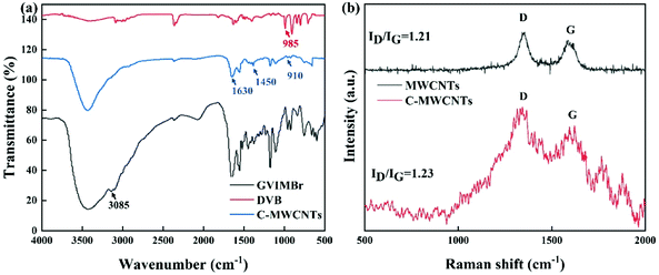
Fig. 3a shows the FTIR spectra region from 500 cm−1 to 4000 cm−1 of DVB, GVIMBr and C-MWCNTs. Among them, 910 cm−1 is the vibration peak of epoxy group, and 985 cm−1 is the stretching vibration peak of the suspended double bond, which has completely disappeared in the FTIR spectrum of C-MWCNTs, indicating that the double bond has been polymerized. Two peaks at 1630 cm−1 and 1450 cm−1 belong to the vibration peak of benzene ring and imidazole ring, respectively. The peak at 3085 cm−1 belongs to the C![[double bond, length as m-dash]](https://www.rsc.org/images/entities/char_e001.gif) C stretching vibration in the benzene ring.27,28 These peaks are all reflected in the FTIR spectra of C-MWCNTs, indicating that the surface polymers of MWCNTs exist as copolymers. Fig. 3b shows the Raman spectra of MWCNTs and C-MWCNTs. Compared with MWCNTs, the background noise of C-MWCNTs Raman peak is very obvious, and the standard peak of the C atom becomes very weak. This indicates that the coating of the outer polymer is very dense. In addition, the D and G peaks are the hybrid peaks of MWCNTs. The ratio of the two peak areas does not change much before and after copolymerization, which proves that the integrity of modified MWCNTs is well preserved.
C stretching vibration in the benzene ring.27,28 These peaks are all reflected in the FTIR spectra of C-MWCNTs, indicating that the surface polymers of MWCNTs exist as copolymers. Fig. 3b shows the Raman spectra of MWCNTs and C-MWCNTs. Compared with MWCNTs, the background noise of C-MWCNTs Raman peak is very obvious, and the standard peak of the C atom becomes very weak. This indicates that the coating of the outer polymer is very dense. In addition, the D and G peaks are the hybrid peaks of MWCNTs. The ratio of the two peak areas does not change much before and after copolymerization, which proves that the integrity of modified MWCNTs is well preserved.
XPS was used to analyze the elemental composition of the composite nanoparticles. Compared with the XPS energy spectrum of MWCNTs, the energy spectrum of C-MWCNTs has more O 1s and N 1s binding energy peaks (Fig. 4a). The Gauss–Lorentz function centered at 284.6 eV (corresponding to the C–C binding energy from the internal reference) with the addition of other symmetric Gaussian peaks is used to deconvolute the asymmetric C 1s spectra of copolymerized MWCNTs (Fig. 4b), based on the contribution of graphite-like walls and carbon atoms of the attached molecules. The peaks at approximately 284.7 eV and 285.5 eV are assigned to sp2 graphite-like C atoms and sp3 C atoms, respectively. The peak at 284.5 eV is a satellite peak caused by excitation losses in π–π* transitions and π-plasmon (π-satellite). The peaks at 286.7 eV and 286.2 eV correspond to the epoxy group (C–O) and imidazole structure (C–N).29–31 In addition, peaks in N 1s (Fig. 3c) spectra at 399.7 eV and 398.1 eV are attributed to the amine (–N–C–), and imine (![[double bond, length as m-dash]](https://www.rsc.org/images/entities/char_e001.gif) N–) nitrogen of the imidazole ring.32 Therefore, XPS binding proves that GVIMBr and DVB have close binding with MWCNTs.
N–) nitrogen of the imidazole ring.32 Therefore, XPS binding proves that GVIMBr and DVB have close binding with MWCNTs.
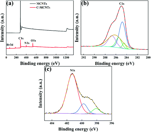 | ||
| Fig. 4 (a) XPS images of MWCNTs and C-MWCNTs, and (b and c) (b) C 1s, (c) N 1s XPS spectra of C-MWCNTs. | ||
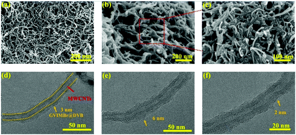
Fig. 5b and d show that GVIMBr and DVB are coated on the surface of MWCNTs by π–π conjugation. Compared with the smooth surface of unmodified MWCNTs (Fig. 5a), the surface of C-MWCNTs becomes obviously rough. The TEM images (Fig. 5d–f) demonstrate that the modified MWCNTs have a clear rough cladding layer, i.e., copolymer of GVIMBr and DVB. This indicates that the copolymer is uniformly and completely coated on the surface of MWCNTs, which is mainly due to the cross-linking agent DVB connecting the copolymer and MWCNTs to forming a stable cross-linked network. The thickness of the coating layer is controlled to be uniform at approximately 2–6 nm, and the complete polymer coating layer effectively prevents the agglomeration of MWCNTs and retains the properties of MWCNTs. The polymer shell also helps to improve the compatibility between the MWCNTs and the matrix resin and achieve good dispersibility within the matrix material, which provides a realistic conditions for the preparation of polymer-based composites.
3.2. Static mechanical characterization
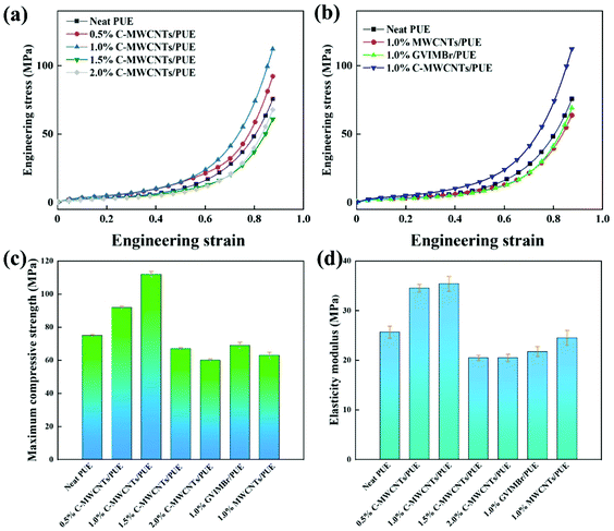
The effect of GVIMBr, MWCNTs and C-MWCNTs contents on the compression property of PUE is shown in Fig. 6a and b. The compression properties of C-MWCNTs/PUE are not improved with increasing C-MWCNTs. When the addition amount of C-MWCNTs are 1.0 wt%, the compression properties of C-MWCNTs/PUE is significantly enhanced (Fig. 6c and d). The maximum compressive strength and elasticity modulus of the 1.0 wt% C-MWCNTs/PUE are increased by 46.3% and 37.8% as high as the neat PUE, respectively. In this case, the uniformly dispersed C-MWCNTs in C-MWCNTs/PUE play a significant role in the load transfer between the matrix and the C-MWCNTs, thereby significantly improving the mechanical properties of the C-MWCNTs/PUE. On the other hand, the increase in physical crosslinking density also helps to improve the mechanical properties of the C-MWCNTs/PUE. The 1.0 wt% addition of GVIMBr has no effect on the compressive properties of PUE, which is attributed to the fact that GVIMBr has good compatibility with PUE, but its strength is not the same as that of nanoparticles. However, the addition of 1.0 wt% MWCNTs has a negative impact on the compression performance of PUE (Fig. 6b). The reason is that the compatibility and dispersibility of MWCNTs are poor, and the force cannot be transferred from the PUE matrix to MWCNTs. Adding GVIMBr and MWCNTs separately is not ideal to improve the PUE compression performance. The π–cation interaction and DVB cross-linking effectively improve the cohesion of the C-MWCNTs, enhance the compatibility and dispersion of MWCNTs in PUE, and give full play to the excellent mechanical properties of MWCNTs.3.3. Dynamic impact test
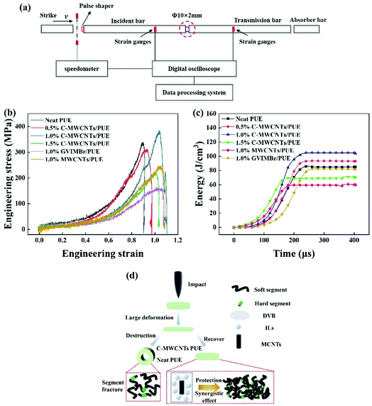
The fundamental difference between dynamic and quasi-static experiments is that the strain rate effect and inertial effect (stress wave effect) in dynamic experiments are interrelated and influence each other. Therefore, decoupling the strain rate effect and stress wave effect is a key problem to be solved in dynamic experiments. There are many methods of dynamic mechanics test, such as drop hammer impact test, Taylor impact test and specially designed hydraulic servo testing machine. Compared with these experiments, the SHPB experiment has obvious advantages in testing dynamic mechanical properties of materials, mainly including: (1) the experimental method can skillfully measure the stress–strain at the same position of the sample in the dynamic experiment, and the device has a simple structure and convenient operation; (2) it is convenient to control the incident waveform, so that the stress balance can be achieved in the experiment; (3) the parts in the experiment can be adjusted according to the different materials being tested; (4) the experimental method is theoretically mature, and the experimental results can be verified by numerical simulation.Therefore, SHPB is used for the dynamic impact resistance test of elastomers in this study. The Hopkinson pressure bar is mainly composed of bullet, incident bar, transmission bar and absorption bar, which can be used for data collection and processing with oscilloscope (Fig. 7a). Due to the poor absorption performance of polymer materials for transmitted waves, aluminum alloy rods are selected in this experiment and strain gauges are equipped at the end of the incident rod and the beginning of the transmission rod to facilitate the collection of transmitted waves.
In the SHPB test, the ratio of cylindrical specimen diameter to height has a great influence on the final reliable data. For soft materials such as PUE, a smaller ratio of length to diameter (L/D = 0.2) is beneficial to avoid the end effect and inertia effect, and to maintain uniform deformation and stress balance. In addition, the friction during the impact will also have an impact on the experimental results, so evenly applied Vaseline on the rod end is beneficial to reduce the impact of friction on the test. The dynamic stress, strain and strain rate are calculated using the initial cross-sectional area and length of the sample, since the change of sample size with time cannot be measured accurately and the change of sample size after impact is very small.
According to the one-dimensional wave propagation theory,33,34 the strains recorded by the incident, transmitted and reflected waves are used to derive the variation of stress, strain and strain rate with time. They have the following relationships:
 | (1) |
 | (2) |
 | (3) |
The energy absorbed by a material under a high-speed impact is defined as the strain energy (U) per unit volume (V), which is equal to the area of the stress–strain curve measured from ε0 to ε1.35,36
The dynamic failure behavior of neat PUE and C-MWCNTs/PUE is studied by using Hopkinson pressure bar (SHPB) under 0.2 MPa impact force (the limit failure force of neat PUE). Fig. 7b shows representative engineering stress–strain curves of neat PUE and C-MWCNTS PUE, including mechanical parameters such as dynamic ultimate strength, absorbed energy and elongation. Apparently, incorporation of MWCNTs with or without GVIMBr@DVB has a significant impact on the dynamic strength (the peak value) of PUE. It is worth noting that, compared with neat PUE, the dynamic ultimate strength of the GVIMBr/PUE and MWCNTs/PUE is greatly decreased. However, their elongation is increased to varying degrees, indicating that the addition of GVIMBr and MWCNTs improves the flexibility of PUE. In contrast, compared with neat PUE, the dynamic ultimate strength and elongation of 1.0 wt% C-MWCNTs/PUE (380 MPa) increase by 15.2% and 22.2%, respectively. The main reason for the improvement is that C-MWCNTs can have good compatibility and dispersion with PUE, and the excellent mechanical properties of MWCNTs can resist the deformation of external force. Fig. 7c shows the energy absorbed of neat PUE and C-MWCNTs/PUE. Compared with neat PUE (85 J cm−3), the energy absorbed of C-MWCNTs/PUE (105 J cm−3) is increased by 23.6%. This may be due to the synergy between C-MWCNTs and deformation (Fig. 7d) of nanoparticles.23,37
3.4. Damage morphology analysis
Preliminary observation of the specimen surface after impact was performed using an ultra-deep field 3D microscope system. The relationship between macroscopic damage and microstructure is constructed. Neat PUE suffered complete destruction of the central perforation (Fig. 8a), while C-MWCNTs/PUE did not (Fig. 8d). Through further magnification observation, there are obvious propagation cracks and failure fragments near the failure boundary of neat PUE (Fig. 8b and c). During the impact, the heat concentration and stress concentration of neat PUE are consistent with the crack propagation direction and transferred to the central area, resulting in brittle fracture of the neat PUE. C-MWCNTs/PUE showed some cracks and burst bubbles on the surface, but the whole remained intact (Fig. 8e and f). This may be due to the good compatibility of C-MWCNTs with the PUE matrix, which enhances the interface interaction between the nanofillers and the PUE matrix, resulting in part of the external impact energy being absorbed by the nanofillers.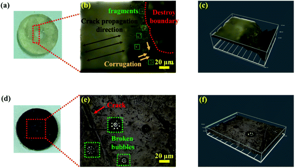 | ||
| Fig. 8 (a and d) Morphology, (b and e) ultra-depth of field 3D microtopography images and (c and f) 3D topography images of (a–c) neat PUE and (d–f) C-MWCNTs/PUE after impact. | ||
The surface morphologies of neat PUE and C-MWCNTs/PUE were studied to understand the reason for crack formation and mechanical changes of the elastomer by using SEM. As shown in Fig. 9, compared with the neat PUE without impact (Fig. 9a), the neat PUE surface becomes abnormally rough, with many macroscopic cracks and extensive areas of irreversible deformation. By magnifying the local area (Fig. 9c), a large number of stress concentration failure zones are observed. This is caused by the continuous expansion and accumulation of radial and circumferential shear cracks (Fig. 9d). In contrast, C-MWCNTs/PUE (Fig. 9b and e) shows only a relatively small number of radial and circumferential microcracks on the surface, and no extensive damage is observed. Using the same method for the magnified observation of the local area (Fig. 9f), the microscopic surface of C-MWCNTs/PUE is rough and shows many microscopic cracks. However, these cracks are more uniformly distributed in the region, and there is no stress concentration or deformation failure zone compared to the neat PUE. Therefore, on the micro level, there is no obvious damage on the surface of C-MWCNTs/PUE.
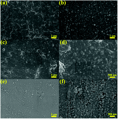 | ||
| Fig. 9 SEM images of (a) neat PUE and (b) C-MWCNTs/PUE surfaces before impact loading, (c and d) neat PUE and (e and f) C-MWCNTs/PUE surfaces under 0.2 MPa impact loading. | ||
The fractures (liquid nitrogen embrittlement) of neat PUE and C-MWCNTs/PUE are observed using SEM to investigate the dispersion and compatibility of C-MWCNTs in the PUE matrix. The fracture of neat PUE is smoother (Fig. 10a), while the fracture of C-MWCNTs/PUE is particularly rough (Fig. 10c). This is because the addition of C-MWCNTs filler increases the overall density of PUE and improves the brittle fracture toughness of C-MWCNTs/PUE. In addition, it can be clearly seen from Fig. 10d that C-MWCNTs have good dispersion in PUE, good compatibility with the PUE matrix, and no flaking or floating phenomenon. This is also an important reason for the improved impact resistance of C-MWCNTs/PUE.
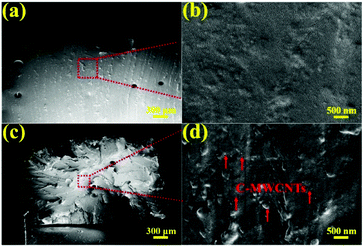 | ||
| Fig. 10 (a and c) SEM images of (a) neat PUE and (c) C-MWCNTs/PUE fracture, and (b and d) High magnification SEM images corresponding to the selected area in (a and c). | ||
4. Conclusions
Here, the improvement of static compression performance and dynamic impact resistance in this research is related to the microstructure. Combined with previous studies, the relationship between macro-mechanical properties and micro-structure is constructed, and the following conclusions are made. (1) The interface interaction is the key to improving the various properties (including thermodynamic properties, dielectric properties and corrosion resistance et al.) of nano-filler/polymer matrix, and the good interface between nano-filler and polymer matrix depends on the dispersibility and compatibility of nano-filler. From the microscopic point of view, the C-MWCNTs prepared in this experiment participated in the curing cross-linking process of PUE through the epoxy group in ionic liquid, which gives the C-MWCNTs good compatibility and dispersion in PUE. The evidence is shown by SEM of the surface and section morphology of C-MWCNTs/PUE. There is no aggregation of nano-fillers on the surface, and nano-fillers in the fracture are uniformly embedded in the PUE matrix. From the macroscopic point of view, 1.0% MWCNTs added to PUE had a negative effect on the mechanical properties of PUE, while 1.0% C-MWCNTs added to PUE greatly enhanced the mechanical properties of PUE. The inherently high specific surface energy of MWCNTs causes serious agglomeration in the polymer mechanism. Moreover, MWCNTs has no functional group on the surface to participate in PUE reaction, which makes MWCNTs have poor compatibility with the PUE matrix. Such MWCNTs are more like an impurity, which affect the internal cross-linking condition of PUE, and greatly reduce the mechanical properties of PUE. Some previous studies also show the importance of interface interactions. For example, Nguyen et al.38 suggested that the gradient mobility of interfacial interactions would have an important effect on the thermodynamic properties of nanofiller/polymer systems. Falkovich et al.39 used molecular dynamics studies to find that the ordered arrangement on the interface of nano-filled polymer results in its superior mechanical properties to the unfilled amorphous polymer. The ordered arrangement of nano-filler/polymer interface leads to good interface interaction, and the ordered arrangement is caused by the induction of nano-filler. Zhu et al.40 demonstrated that in nanofiller/polymer systems, rough sections have better interface interactions and more uniform microphase separation structures than smooth polymer sections, which have a significant impact on the significant improvement of mechanical properties. This is consistent with the results obtained in this paper.(2) On the premise of good interfacial interaction, the transfer of external force from the polymer matrix to rigid nanoparticles is an important reason for the improvement of mechanical properties.41,42 When the impact force is loaded on C-MWCNTs/PUE, the energy dissipation of lightweight polymer nanocomposites can be improved by using the low-density electrostatic interaction through the deformation of MWCNTs and the stick-slip mechanism between the polymer chains wound around the MWCNTs. The mechanical stability of the structure is achieved, which explains the higher energy absorption of C-MWCNTS/PUE under dynamic impact compared to neat PUE.
(3) Synergy effect between ionic liquids, DVB and MWCNTs. The explanation of the mechanism of synergy is complicated. In this article, the C-MWCNTs filler prepared by free radical polymerization is a multi-nano composite system of polymer–inorganic nanoparticles. Its typical feature is that by locally increasing the density of non-covalent bonds with higher energy, the atomic friction between the two composite material components is greatly enlarged. Michela Talò et al.43 mentioned a new material design concept, that is, the microcrystalline structure nucleated around the carbon nanofiller becomes a source of enhanced energy dissipation. The concept of rheology is a nano-piston unit, composed of a carbon nanotube (CNT), as a nano-filler with a microcrystalline structure, through unconventional and reversible overcoming of the interfacial interaction force, rotating from an energy stable state to the adjacent state. In a larger strain range, the efficiency of this new sliding crystal mechanism has been proven, and it has a higher dissipation capacity. This new mechanism explains the improved energy absorption of C-MWCNTs/PUE, while MWCNTs/PUE and GVIMBr/PUE do not contribute to the energy absorption capacity of PUE.
In this study, a vinyl imidazolium ionic liquid with an epoxy group was synthesized. Composite nano-filler C-MWCNTs with coated structure was prepared by the free radical polymerization reaction between the ionic liquid and DVB. Due to the C-MWCNTs have good compatibility and dispersibility in the PUE matrix, adding 1.0% C-MWCNTs during the curing process of PUE can greatly improve the mechanical properties of PUE. Compared with neat PUE, the maximum compressive strength, dynamic ultimate strength and energy absorbed of C-MWCNTs/PUE are increased by 46.3%, 15.2%, and 23.6%, respectively. Besides, the PUE has undergone perforation damage, while the C-MWCNTs/PUE has not undergone extensive damage. The addition of 1.0% C-MWCNTs improves the compression strength and impact toughness of PUE, and avoids the damage and softening caused by stress concentration and heat concentration under the impact effect. In summary, using DVB as a bridge between ILs and MWCNTs has simple operation, high efficiency, and retains the original performance of MWCNTs, which can become an effective way to functionalize MWCNTs in the future. Based on the high impact resistance of C-MWCNTs/PUE, it has bright application prospects in the field of impact protection.
Author contributions
Zehui Xiang and Fan Hu contributed equally. Zehui Xiang: writing – original draft, data curation, formal analysis, investigation. Fan Hu: validation, investigation. Xueyan Wu: investigation, software. Biao Zhang: supervision, writing – review & editing. Fugang Qi: visualization, validation, supervision. Nie Zhao: conceptualization, supervision. Xiaoping Ouyang: project administration, supervision.Conflicts of interest
There are no conflicts to declare.Acknowledgements
This work is supported by High Technology Research and Development Program of Hunan Province of China (2022GK4038); Hunan Provincial Natural Science Foundation of China (2021JJ30646, 2020JJ4086 and 2020JJ5530); Educational Commission of Hunan Province of China (20B579 and 19B570); Innovation Team of Hunan Province (2018RS3091); National Natural Science Foundation of China (12027813).References
- C. Zhao, Y. Wang, M. Ni, X. He, S. Xuan and X. Gong, Composites, Part A, 2021, 143, 106285 CrossRef CAS.
- Q. Wang, J. Zhang, X. Wang and Z. Wang, Appl. Surf. Sci., 2020, 526, 146657 CrossRef CAS.
- L. Yu and A. L. Skov, RSC Adv., 2017, 7, 45784–45791 RSC.
- T. Sadowski, P. Golewski and E. Craciun, Compos. Struct., 2021, 258, 113375 CrossRef.
- H. C. Zhang, B. H. Kang, L. S. Chen and X. Lu, Polym. Test., 2020, 87, 106521 CrossRef CAS.
- C. Fallon and G. J. Mcshane, Int. J. Impact Eng., 2020, 146, 103700 CrossRef.
- Y. Yuan, C. Peng, D. Chen, Z. Wu, S. Li and T. Sun, et al., Composites, Part A, 2021, 149, 106573 CrossRef.
- A. M. Palve and R. K. Gupta, Polyurethane Chemistry: Renewable Polyols and Isocyanates, American Chemical Society, 2021, ch. 8, vol. 1380, pp. 225–255 Search PubMed.
- O. S. Kwon, D. Lee, S. P. Lee, Y. G. Kang, N. C. Kim and S. H. Song, RSC Adv., 2016, 6, 59970–59975 RSC.
- B. Likozar and Z. Major, Appl. Surf. Sci., 2010, 257, 565–573 CrossRef CAS.
- Z. Wang, M. Li, Y. Zhang, J. Yuan, Y. Shen and L. Niu, et al., Carbon, 2007, 45, 2111–2115 CrossRef CAS.
- A. Thess, R. Lee, P. Nikolaev, H. Dai, P. Petit and J. Robert, et al., Science, 1996, 273, 483–487 CrossRef CAS PubMed.
- N. Karousis, N. Tagmatarchis and D. Tasis, Chem. Rev., 2010, 110, 5366–5397 CrossRef CAS PubMed.
- P. Damlin, M. Suominen, M. Heinonen and C. Kvarnström, Carbon, 2015, 93, 533–543 CrossRef CAS.
- M. Matandabuzo and P. A. Ajibade, J. Mol. Liq., 2018, 268, 284–293 CrossRef CAS.
- J. Łuczak, M. Paszkiewicz, A. Krukowska, A. Malankowska and A. Zaleska-Medynska, Adv. Colloid Interface Sci., 2016, 230, 13–28 CrossRef PubMed.
- F. Hu, F. Qi, Z. Xiang, B. Zhang, F. Qi and N. Zhao, et al., Compos. Commun., 2021, 27, 100876 CrossRef.
- Y.-K. Yang, C.-E. He, R.-G. Peng, A. Baji, X.-S. Du and Y.-L. Huang, et al., J. Mater. Chem., 2012, 22, 5666–5675 RSC.
- D. M. Correia, L. C. Fernandes, P. M. Martins, C. García-Astrain, C. M. Costa and J. Reguera, et al., Adv. Funct. Mater., 2020, 30, 1909736 CrossRef CAS.
- S. Zhang, Q. Zhang, Y. Zhang, Z. Chen, M. Watanabe and Y. Deng, Prog. Mater. Sci., 2016, 77, 80–124 CrossRef CAS.
- J. Abraham, J. Thomas, N. Kalarikkal, S. C. George and S. Thomas, J. Phys. Chem. B, 2018, 122, 1525–1536 CrossRef CAS PubMed.
- B. Likozar, Sci. Iran., 2010, 17, 35–42 CAS.
- L. Liu, Z. Zheng, C. Gu and X. Wang, Compos. Sci. Technol., 2010, 70, 1697–1703 CrossRef CAS.
- J. Sanes, N. Saurín, F. J. Carrión, G. Ojados and M. D. Bermúdez, Composites, Part B, 2016, 105, 149–159 CrossRef CAS.
- B. Likozar, Soft Matter, 2011, 7, 970–977 RSC.
- L. Zhao, Y. Li, Z. Liu and H. Shimizu, Chem. Mater., 2010, 22, 5949–5956 CrossRef CAS.
- Z. Guo, Q. Jiang, Y. Shi, J. Li, X. Yang and W. Hou, et al., ACS Catal., 2017, 7, 6770–6780 CrossRef CAS.
- J. Zhang, X. Li, Z. Zhu, T. Chang, X. Fu and Y. Hao, et al., Adv. Sustainable Syst., 2021, 5, 2000133 CrossRef CAS.
- C. H. Ahn, Y. Baek, C. Lee, S. O. Kim, S. Kim and S. Lee, et al., Ind. Eng. Chem., 2012, 18, 1551 CrossRef CAS.
- C. M. Damian, S. A. Garea, E. Vasile and H. Iovu, Composites, Part B, 2012, 43, 3507–3515 CrossRef CAS.
- E. A. Skryleva, Y. N. Parkhomenko and I. M. Karnaukh, Fullerenes, Nanotubes, Carbon Nanostruct., 2016, 24, 535–540 CrossRef CAS.
- A. K. S. Ang, E. T. Kang, K. G. Neoh, K. L. Tan, C. Q. Cui and T. B. Lim, Polymer, 2000, 41, 489–498 CrossRef CAS.
- H. Zhao, G. Gary and J. R. Klepaczko, Int. J. Impact Eng., 1997, 19, 319–330 CrossRef.
- C. Bacon, Int. J. Impact Eng., 1999, 22, 55–69 CrossRef.
- Z. Rongxing, H. Hong, C. Nanliang and F. Xunwei, J. Compos. Mater., 2005, 39, 525–542 CrossRef.
- K. Shaker, A. Jabbar, M. Karahan, N. Karahan and Y. Nawab, J. Compos. Mater., 2017, 51, 81–94 CrossRef CAS.
- L. Zhang, J. Pu, L. Wang and Q. Xue, ACS Appl. Mater. Interfaces, 2015, 7, 8592–8600 CrossRef CAS PubMed.
- H. K. Nguyen, X. Liang, M. Ito and K. Nakajima, Macromolecules, 2018, 51, 6085–6091 CrossRef CAS.
- S. G. Falkovich, V. M. Nazarychev, S. V. Larin, J. M. Kenny and S. V. Lyulin, J. Phys. Chem. C, 2016, 12, 6771–6777 CrossRef.
- B. Zhu, Y. Wang, H. Liu, J. Ying, C. Liu and C. Shen, Compos. Sci. Technol., 2020, 12, 108048 CrossRef.
- G. Wang, L. Liu and Z. Zhang, Composites, Part A, 2021, 141, 106212 CrossRef CAS.
- Y. Hu and J. L. Ding, Carbon, 2016, 107, 510–524 CrossRef CAS.
- M. Talò, G. Lanzara, B. Krause, A. Janke and W. Lacarbonara, ACS Appl. Mater. Interfaces, 2019, 11, 38147–38159 CrossRef PubMed.
| This journal is © The Royal Society of Chemistry 2022 |

