
 Open Access Article
 This Open Access Article is licensed under a
 Creative Commons Attribution 3.0 Unported Licence
Tailoring of the photocatalytic activity of CeO2 nanoparticles by the presence of plasmonic Ag nanoparticles†
Shuang
Zhao
a,
Marc
Riedel
b,
Javier
Patarroyo
 c,
Neus G.
Bastús
c,
Victor
Puntes
cde,
Zhao
Yue
*f,
Fred
Lisdat
*b and
Wolfgang J.
Parak
*a
c,
Neus G.
Bastús
c,
Victor
Puntes
cde,
Zhao
Yue
*f,
Fred
Lisdat
*b and
Wolfgang J.
Parak
*a
aFachbereich Physik, CHyN, Universität Hamburg, 22761 Hamburg, Germany. E-mail: wolfgang.parak@uni-hamburg.de
bBiosystems Technology, Institute of Life Sciences and Biomedical Technologies, Technical University of Applied Sciences Wildau, 15745 Wildau, Germany. E-mail: flisdat@th-wildau.de
cInstitut Català de Nanociència i Nanotecnologia (ICN2), CSIC and BIST, Campus UAB, Bellaterra, 08193 Barcelona, Catalonia, Spain
dVall d'Hebron Institut de Recerca (VHIR), 08035 Barcelona, Catalonia, Spain
eICREA, Pg. Lluís Companys 23, 08010 Barcelona, Catalonia, Spain
fDepartment of Microelectronics, Nankai University, 30071 Tianjin, China. E-mail: yuezhao@nankai.edu.cn
First published on 27th July 2022
Abstract
The present study investigates basic features of a photoelectrochemical system based on CeO2 nanoparticles fixed on gold electrodes. Since photocurrent generation is limited to the absorption range of the CeO2 in the UV range, the combination with metal nanoparticles has been studied. It can be shown that the combination of silver nanoparticles with the CeO2 can shift the excitation range into the visible light wavelength range. Here a close contact between both components has been found to be essential and thus, hybrid CeO2@Ag nanoparticles have been prepared and analyzed. We have collected arguments that electron transfer occurs between both compositional elements of the hybrid nanoparticles.The photocurrent generation can be rationalized on the basis of an energy diagram underlying the necessity of surface plasmon excitation in the metal nanoparticles, which is also supported by wavelength-dependent photocurrent measurements. However, electrochemical reactions seem to occur at the CeO2 surface and consequently, the catalytic properties of this material can be exploited as exemplified with the photoelectrochemical reduction of hydrogen peroxide. It can be further demonstrated that the layer-by layer technique can be exploited to create a multilayer system on top of a gold electrode which allows the adjustment of the sensitivity of the photoelectrochemical system. Thus, with a 5-layer electrode with hybrid CeO2@Ag nanoparticles submicromolar hydrogen peroxide concentrations can be detected.
Introduction
Semiconductor nanostructures are valuable building blocks in electrochemical systems since they enlarge the possibilities in sensing and energetic applications. They introduce light as additional tool in order to adjust electrochemical reactions. As a basic feature, charge carriers are generated inside these nanostructures, which cannot only show recombination leading to luminescence properties, but also allow the involvement of these light-triggered charge carriers in electrochemical reactions. This can be on the one hand electron transfer to the underlying electrode and on the other hand reactions of acceptor or donor molecules with the excited nanostructures. In this way, the detected photocurrent becomes a measure of the concentration of the respective species.1,2 Conceptually the photocurrent can be thus, used as analytical tool with a good signal to noise ratio. Since only the illuminated area will be analyzed, the application of using a focused light source for multiplexed detection on a small electrode surface has been recently demonstrated experimentally.3,4 Another interesting results from the fact that the generation of electron–hole pairs also means, that the energetic situation of the charge carriers is changed upon illumination. This will allow the collection of electrons from oxidation processes at very low potential and the transfer of electrons to acceptor molecules at rather high potentials.The attractiveness of photoelectrochemical detection schemes has resulted in numerous developments in the field. One cannot only directly detect donor or acceptor molecules, but also combinations with specific enzymatic reactions are feasible. Here different strategies from amperometric biosensors have been transferred to photobioelectrochemical detection schemes. In the focus so far have been mainly coupling strategies in which the detection of enzymatic products (or co-substrates) has been used. Examples are oxygen,5–7 NADH,8–10 thiocholine,11,12 or phenolic substances.13 Only few systems have been reported so far on photoelectrochemical systems exploiting direct electron transfer with proteins,14–17 although the coupling of enzymatic reactions to semiconductor nanoparticles (NPs) has gained increasing interest. As an alternative, mediators can also be used for the communication of enzymes with semiconductor nanostructures – first examples have been reported here.18 In addition to enzymes, also biospecific binding reactions have been coupled to photoactive electrodes, enlarging the applicability of such systems even further.19–22
There is a variety of semiconductor nanostructures which have been used for the construction of such photoelectrochemical schemes. Examples are quantum dots,6,22,23 nanowires,8,24,25 nanoclusters,26–28 and others. The light interaction of such structures can only be exploited when the wavelength used for excitation matches with the absorption properties of the material. Here one can see a limitation since many NPs can only be excited by UV light. For the application however, one should avoid the simultaneous excitation of the transducer and the analyte molecules since this may give raise to unwanted reactions or disturbances of the defined concentration analysis as has been demonstrated with InGaN nanowires.8
Different strategies can be seen to overcome this issue. One is based on the application of hybrid NPs. Recently we have shown how the photocatalytic properties of CeO2 NPs can be enhanced by the presence of plasmonic Au NPs.3 Presence of the Au NPs allowed for amplifying the photocurrent response in the visible light regions where the Au NPs, but not the CeO2 NPs absorb light. The best effect was observed when the Au NPs were directly connected to the CeO2 NPs in the form of hybrid NPs, without interfacial organic separation layer.
In the present work we extend this strategy to the case of plasmonic Ag NPs (i.e. Ag/CeO2 hybrid NPs are investigated) in order to address the following questions: is the mechanism to couple plasmonic NPs as light harvesters and charge transfer mediators to photocatalytic NPs of general nature? (i.e. can the approach be extended to plasmonic NPs others than Au?) Can the multi-interface between redox couples in solution, the immobilized hybrids of plasmonic and photocatalytic NPs, and the underlying gold electrode be described by a band structure diagram? CeO2 and Ag have already been combined in several studies, but with very different background. In Table 1 a short summary about previous work on using Ag/CeO2 nanocomposites for photocatalysis is given.
| Nanomaterial | Application | Enhancement mechanism | Ref. |
|---|---|---|---|
| Ag NPs decorated with CeO2 NPs | Realizing enhanced surface enhanced Raman scattering (SERS) properties and improved sensing performance of 4-aminothiophenol (4-ATP). | Charge transfer, more SERS hot spots present in the Ag on the CeO2 surfaces | 29 |
| Ag/CeO2 | Ag/CeO2 antibacterial activity towards Gram positive and Gram negative strains of bacteria | Soot oxidation of CeO2 | 30 |
| Ag/CeO2 nanocomposites | Better photocatalytic efficacy and degradation towards organic pollutants | Lower rate recombination of charge carriers | 31 |
| Ag/Au doped CeO2 NPs | Degradation of organic pollutants | Morphology, particle size, electron–hole recombination, and oxygen vacancies. | 32 |
| Ag NPs decorated on CeO2 supports | Superior photocatalytic activity for the dye auramine O | Localized surface plasmon resonance (LSPR) | 33 |
| Ag@CeO2 core–shell NPs | O2 evolution and methylene blue (MB) dye degradation | Localized surface plasmon resonance (LSPR) | 34 |
| 3D flower-like Ag–CeO2–ZnO nanocomposites | Enhanced performance for photocatalytic CO2 reduction to CO and CH4 | Prolonged absorption in the visible light region induced by the surface plasmon resonance (SPR) effect; efficient separation of photogenerated charges, and the Z-scheme configuration | 35 |
| Ag@CeO2–Au nanorods | Improved conversion efficiency of benzyl alcohol to benzaldehyde | Plasmonic scattering-enhanced absorption | 36 |
| CeO2/Ag nanocomposites | Enhanced photocatalytic activity and electrochemical behavior towards Hg(II) | Electron transfer | 37 |
Results and discussion
Characterization of the nanoparticles
CeO2 NPs, Ag NPs of different size, and hybrid Ag/CeO2 NPs have been synthesized adopting previously published protocols.38,39 In Fig. 1, representative transmission electron microscopy (TEM) images of the different NPs used in the study are shown. Sodium citrate-coated (and thus, negatively charged) Ag NPs are hereby synthesized that their inorganic core diameter dc corresponds to the diameter of the Ag core in the Ag/CeO2 NPs. From the size distribution (cf.Fig. 1d) obtained from the TEM images (Fig. 1a), a mean value of dc = 5.8 ± 0.4 nm can be found for the Ag NPs. The CeO2 NPs (see Fig. 1b for a TEM image) with a mean core diameter of dc = 15.4 ± 1.6 nm (cf.Fig. 1e for their size distribution) appear to have a lower compactness, and may be porous. The TEM images suggest that these NPs are not crystalline over their entire volume. TEM images of the Ag/CeO2 hybrid NPs (cf.Fig. 1c) reveal the formation of structures composed of a central Ag core surrounded by cerium oxide domains. The CeO2 domains covering the Ag cores have also a low compactness and very similar to the pure CeO2 NPs. The CeO2 domains do not fully isolate the Ag cores, therefore the Ag cores are in direct contact with the aqueous solution in which they are dispersed. The diameter of the hybrid Ag/CeO2 NPs as determined by TEM is dc = 15.8 ± 2.3 nm (cf.Fig. 1g), while the inner Ag core has a diameter of dc = 7.8 ± 2.1 nm (cf.Fig. 1f).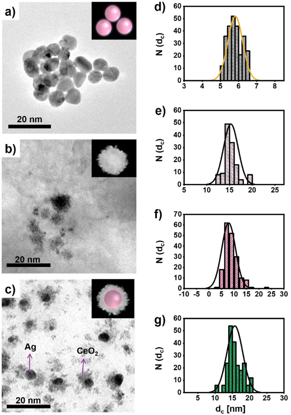 | ||
| Fig. 1 Transmission electron microscopy (TEM) images of the NPs including (a) Ag NPs, (b) CeO2 NPs, and (c) Ag/CeO2 hybrid NPs, together with the size distribution N(dc) of their inorganic diameters dc, as shown in (d)–(g): (d) Ag NPs, (e) CeO2 NPs, (f) the Ag core size of the Ag/CeO2 hybrid NPs, and (g) the whole size of the Ag/CeO2 hybrid NPs. The insets are an artistic guide to the eye in which a sphere symbolizes the Ag cores. Additional TEM images are shown in Fig. S1 in the ESI.† | ||
We want to point out that although the Ag parts of the Ag/CeO2 hybrid NPs and the Ag NPs have almost the same average sizes, the size distributions of the TEM images given in Fig. 1 show that the size distribution of the Ag NPs is more uniform than that of the Ag/CeO2 NPs. This is due to the fact that the Ag cores have been produced following two different synthetic procedures, and consequently the level of size control and uniformity of the product is different. While the Ag/CeO2 hybrid NPs have been produced following a one-pot method,39 whereas the plain Ag NPs of similar size are produced following a seeded-growth procedure.38 Despite the versatility of the former, it does not allow for controlling the size of the Ag cores with the same accuracy.
The UV/vis absorption spectra of the three different types of NPs as dispersed in aqueous solution can be seen in Fig. 2. The absorption of pure citrate-stabilized Ag NPs exhibits a surface plasmon resonance peak at λ = 392 nm, which agrees with literature for NPs of the obtained size.40 The CeO2 NPs show a characteristic absorption in the near-ultraviolet region (λ ≈ 270 nm), which arises from the electronic transitions within the sample. The absorption spectrum of the hybrid Ag/CeO2 NPs is given in Fig. 2c. As can be seen, CeO2 coating translates into: (i) the increase of the well-defined absorption of CeO2 in the near-ultraviolet region, (ii) the red-shift of the surface plasmon resonance (SPR) Ag peak position (from 392 to 421 nm), and (iii) the progressive broadening of the plasmon band. These results can be explained by the increased refractive index (n ≈ 2.2) of the dielectric environment surrounding the Ag cores upon CeO2 coating, resulting in a red-shift whose extension depends on the thickness and degree of coating on the Ag cores.
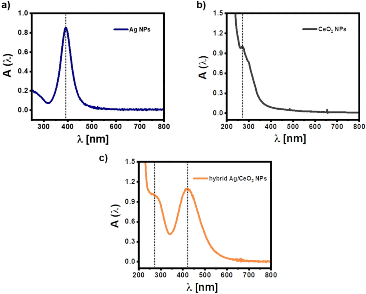 | ||
| Fig. 2 UV-vis absorption spectra A(λ) of (a) pure citric acid stabilized Ag NPs (–), pure CeO2 NPs, and (c) hybrid Ag/CeO2 NPs in the water. Note that the “–” means negative charged, in contrast to the positively charged Ag NPs (+) reported later in this work. Additional spectra are shown in Fig. S1.† | ||
To further study and prove the successful formation of Ag/CeO2 hybrid NPs X-ray photoelectron spectroscopy (XPS) measurements of Ag/CeO2 hybrid NPs and plain Ag NPs were carried out in a previous study.41 In the case of plain Ag NPs, only a doublet has been observed corresponding to the well-known spin–orbit splitting. The determined binding energy (BE) at 368.2 and 374.2 eV, assigned to 3d5/2 and 3d3/2, respectively, corresponds well to metallic Ag. Essentially, the same spectrum is obtained in the case of Ag/CeO2 hybrid NPs.
The crystal structure of the Ag/CeO2 NPs has been further investigated by X-ray diffraction (XRD). As shown in Fig. S2,† two series of peaks are present in the diffraction patterns, which can be assigned to the fluorite (cubic) CeO2 phase (JCPDS 34-0394) and the Ag cubic phase (JCPDS 04-0783). The diffraction peaks of the CeO2 domain are broader and weaker, according to the smaller size of the CeO2 crystal domains.
Representative images of high-angle annular dark field scanning TEM (HAADF STEM) of the Ag/CeO2 hybrid NPs demonstrate the systematic formation of Ag/CeO2 NPs consisting of an Ag core surrounded by a CeO2 shell, see Fig. S3.† Of notice, the Ag cores present the brightest contrast in the HAAD STEM images, due to their Z-contrast. Unlike other common shell components with a continuous phase – such as SiO2, TiO2, Cu2O, and ZnO – the CeO2 layer is not compact nor continuous, indicating that the growth of CeO2 follows Volmer–Weber growth modes, as expected from the large mismatch of lattice parameters between CeO2 (0.5412 nm) and Ag (0.4046 nm). An energy-dispersive X-ray spectroscopy (STEM-EDS) line scan obtained on the hybrid reveals that the hybrid NPs are composed of a Ag and Ce domain, see Fig. S3.† Additionally, the continuous Ce profile in the junction between the 2 domains constitutes a further indication of the tight interaction between Ag and CeO2.
The accessibility of the inner metal core in the hybrid structures was proven by studying the catalytic degradation of 4-nitrophenol (4-NP) by borohydride ions39 in the case of Au/CeO2 hybrid NPs. Although a decrease of the reduction rate of the dye has been observed for the hybrid NPs in comparison to bare Au NPs of similar core sizes, the presence of the CeO2 shell can not prevent the 4-NP from reaching the inner metal core.
Altogether, these results confirm the growth of the CeO2 to the Ag core, and the successful formation of the Ag/CeO2 hybrid NPs.
Photocurrent measurements of single layers of CeO2 NPs in presence of different types and amounts of Ag NPs
Since pure CeO2 NPs have a negative surface charge, direct assembly of these NPs to cysteamine modified gold electrode has been used for immobilization (for details we refer to the ESI†). Here a surface density of approximately n(CeO2 NP) = 5.5 × 1010 cm−2 (cf. Fig. S6†) has been achieved. Note that this low surface coverage is in agreement with previous results,3 which however can be enhanced by the growth of multilayers as reported in the next section (cf. Fig. S10†). For the calculations we refer to the ESI.† A bias voltage U has been applied to the Au electrode in the buffer solution in which the CeO2 NP coated Au electrode surface is immersed and controlled versus an Ag/AgCl reference electrode. Upon pulsed white light illumination, a modulated photocurrent can flow, driven by light-generated electron–hole pairs. For details of the set-up we refer to the ESI.† In Fig. 3a the amplitude of the photocurrent I is plotted versus the bias potential U. As the CeO2 NPs absorb light mainly in the UV region (see Fig. 2b), upon white light illumination, only a small fraction of the incident photons lie in the appropriate spectral range (i.e. the energy of most photons is smaller than the band gap of the CeO2 NPs) and thus, the amplitude of the photocurrent is low.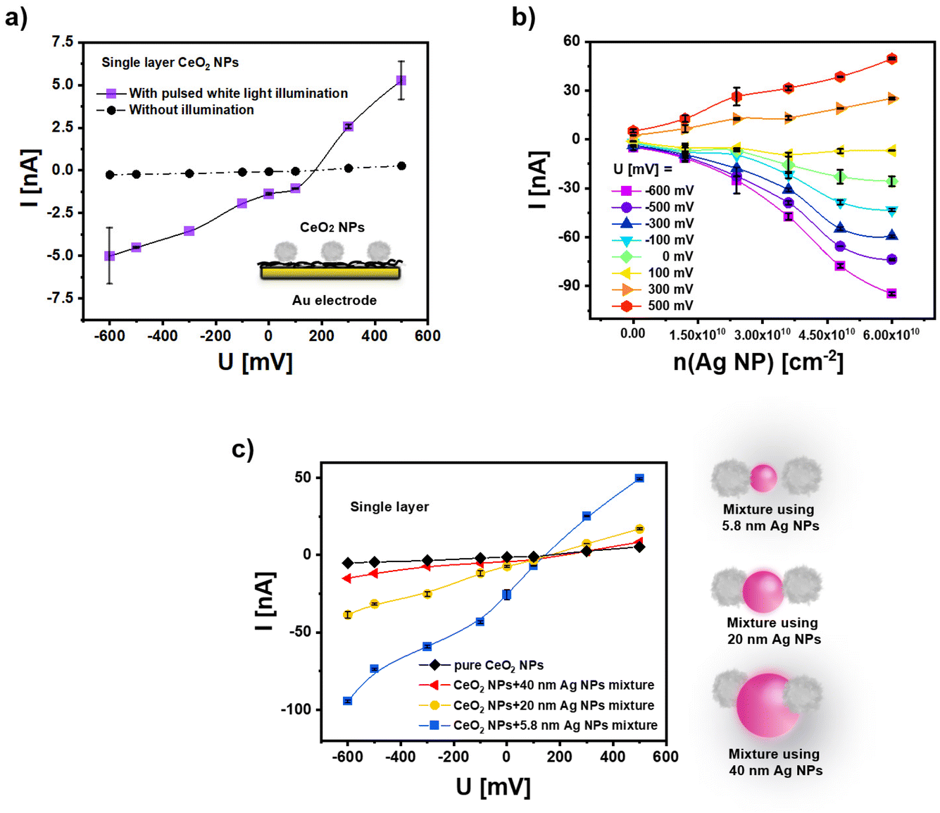 | ||
| Fig. 3 (a) The photocurrent I of pure CeO2 NPs after their immobilization on the cysteamine-modified gold electrode in phosphate-buffered saline (PBS, 0.1 M, pH = 7.4) versus the applied bias voltage U under pulsed white light illumination and without illumination. n(CeO2 NP) = 5.5 × 1010 cm−2. The bias voltage U is the potential difference between the Au electrode and an Ag/AgCl electrode in the buffer. (b) Photocurrent I at different bias potentials U under white light illumination as recorded with electrodes coated with a mixture of CeO2 NPs and Ag (−) NPs with dc = 5.8 ± 0.4 nm. The surface coverage of CeO2 NPs has been maintained at n(CeO2 NP) = 5.5 × 1010 cm−2, whereas the surface coverage of the Ag (−) NPs n(Ag NP) was varied. (c) Photocurrent I in dependence of the bias potential U under white light illumination for mixtures of CeO2 NPs and Ag (−) NPs of different size for the surface coverage of n(CeO2 NP) = 5.5 × 1010 cm−2 (see Fig. S6 and S7†) n(Ag NP) = 6 × 1010 cm−2. The “(−)” refers to the negative charge of the Ag NPs by the citrate ligands. | ||
In order to introduce visible light sensitivity, we have introduced plasmonic Ag NPs as a light harvester, which shall allow charge carrier generation in the CeO2 NPs. In a first approach plasmonic Ag NPs with dc = 5.8 ± 0.4 nm are mixed with the CeO2 NPs and immobilized on the Au electrode. For this, the aqueous solvent of Ag NP solutions is removed by ultrafiltration,42 followed by redispersion of the Ag NPs in an aqueous solution of CeO2 NPs. The modified Au electrode is then incubated with the NP mixture. Again electrostatic interactions with the positively charged cysteamine layer on the Au surface have been exploited. The surface coverage of the electrode with Ag NPs and CeO2 NPs can be determined by dissolving the NPs with aqua regia and measuring elemental Ag and Ce concentrations with inductively coupled plasma mass spectrometry (ICP-MS). Based on the surface area of the coated Au electrode and the amount of Ag and Ce atoms per Ag NP and CeO2 NP, respectively, from the elemental concentrations, the number Ag NPs and CeO2 NPs per surface area of the electrode can be determined. The coatings have been done in a way that the surface coverage of CeO2 NPs is maintained at about n(CeO2 NP) = 5.5 × 1010 cm−2, while the amount of immobilized Ag NPs n(Ag NP) is varied up to a maximum of n(Ag NP) = 6 × 1010 cm−2. As shown in Fig. 3b, the presence of Ag NPs increases the photocurrent in a concentration-dependent manner for positive and negative bias potential (i.e. for cathodic and anodic photocurrents) under white light illumination.
In a second approach, mixtures of CeO2 NPs and Ag NPs of different core diameter (CeO2: one diameter dc = 15.4 ± 1.6 nm Ag: three different diameters: dc = 5.8 ± 0.4 nm, 20 ± 1.2 nm, and 40 ± 3.8 nm) have been applied to the surface. For these experiments the number of NPs has been fixed in the range: n(CeO2 NP) = 5.5 × 1010 cm−2 and n(Ag NP) = 6 × 1010 cm−2, see Fig. 3c. Data show that the photocurrent upon white light illumination is more enhanced for the smaller Ag NPs (at the same number of NPs per surface area). This might be attributed to the fact that for the smaller Ag NPs a larger fraction of their surface may be in contact with the CeO2 NPs, see the sketch in Fig. 3c. For this reason, all further measurements in this work have been done with Ag NPs of dc = 5.8 ± 0.4 nm.
From these experiments we can conclude that light-excited charge carriers in the plasmonic Ag NPs can be used for photocurrent generation with the electrode-fixed CeO2 NPs. This finding is also following the observation in a previous study by mixing Au NPs and CeO2 NPs.3 One can assume electron transfer as an essential mechanism. Such charge carrier transfer consequently should be distance-dependent, i.e. more effective the closer the connection between the CeO2 NPs and the plasmonic NPs is. For the case of Ag NPs we thus, have tried to reduce the distance between the Ag NPs and the negatively charged CeO2 NPs by using positively-charged Ag NPs. In Fig. 4 a comparison of negatively and positively charged Ag NPs is shown. Positive charge has been obtained by replacing the citrate ligand by a polyallylamine hydrochloride – PAH – at the Ag NPs. As given in the sketch of Fig. 4a we anticipate that the distance between Ag (+) NPs and CeO2 NPs should be closer than the distance between Ag (−) NPs and CeO2 NPs. In fact, the recorded photocurrents given in Fig. 4b demonstrate higher photocurrent for the mixture of Ag (+) NPs and CeO2 NPs than for the mixture of Ag (−) NPs and CeO2 NPs.
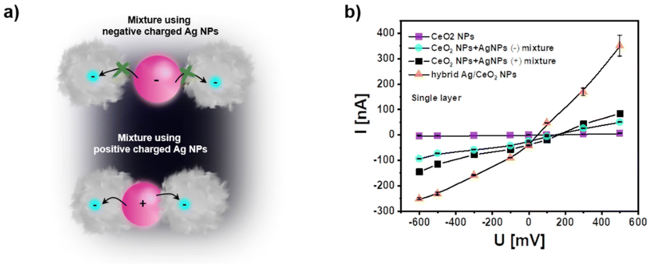 | ||
| Fig. 4 (a) Sketch showing the closer distance between Ag (+) NPs and CeO2 NPs due to electrostatic attraction as compared mixtures of Ag (−) NPs and CeO2 NPs. A closer distance will facilitate charge transfer between both types of NPs. (b) Comparison of photocurrents are recorded with single layers of pure CeO2 NPs, mixtures of CeO2 NPs and Ag (−) NPs, mixtures of CeO2 NPs and Ag (+) NPs, and hybrid Ag/CeO2 NPs. All data were obtained under pulsed white light excitation in PBS (0.1 M, pH = 7.4). The “(−)” and “(+)” refer to the charge of the Ag NPs introduced by different ligands used, citrate and PAH respectively. The NP densities are similar to those in Fig. 3c (see Fig. S8 and S9†). | ||
In a third approach we have applied hybrid NPs since an even closer contact can be obtained when the CeO2 NPs are directly grown on top of the plasmonic Ag NPs. Indeed, data from Fig. 4b demonstrate that the photocurrent is highest for hybrid Ag/CeO2 NPs. In addition, the stability of the photocurrent in the hybrid Ag/CeO2 NPs is higher than for the mixtures of Ag NPs and CeO2 NPs (see Fig. S10†). This is most likely due to a more defined interface in the hybrid Ag/CeO2 NPs which may also decrease photocorrosion.
Photocurrent measurements of multiple layers of CeO2 NPs in presence of different types of Ag NPs
One advantageous property of applying NPs on top of electrodes is the potential for multilayer formation. Since inter-particle electron transfer is feasible, this can result in significant photocurrent amplification. Consequently, multiple layers of Ag NPs and CeO2 NPs have been arranged on top of the gold working electrode using the layer-by-layer assembly and poly(diallyldimethylammonium chloride) (PDDA) as polyelectrolyte. For the case of mixtures of Ag NPs and CeO2 NPs here and in the following only the negatively charged Ag (−) NPs are used to assemble them in the same layer as the negatively charged CeO2 NPs. The Ag (+) NPs with better PEC response have not been used to form these mixed layers because the positively charged PDDA could not be applied to immobilize the likewise charged Ag (+) NPs. Data in Fig. 5 exemplify that for all three cases: CeO2 NPs only, mixtures of Ag NPs and CeO2 NPs, and hybrid Ag/CeO2 NPs, the photocurrent increases with the number of NP layers (both for the anodic and cathodic current direction). Based on the comparison between Fig. 5b and c, it can be seen that the multilayers of the Ag (−) NP and CeO2 NP mixture have always a larger photocurrent than the multilayers formed by CeO2 NPs only. As the CeO2 NP numbers in the just CeO2 NP layers and in the CeO2 NP/Ag (−) NP mix layers are controlled to be rather similar (Fig. S10a†), it can be verified that the Ag (−) NPs can enhance the photo-electrochemical (PEC) response of the CeO2 NPs. Likewise, the hybrid Ag/CeO2 NPs have better PEC performance than the Ag (−) NP and CeO2 NP mixtures. Also here, in each layer, the number of CeO2 NPs (Fig. S10a†) and Ag NPs (Fig. S10b†) has been controlled to be similar for the Ag (−) NP and CeO2 NP mixture and the hybrid Ag/CeO2 NPs. The high photocurrent is likely due to the fact that in the hybrid Ag/CeO2 NPs there is intimate contact between CeO2 and Ag, but in the mixture of Ag (−) NPs and CeO2 NPs the distance between CeO2 and Ag is larger. In addition, photocurrents are also most stable for the hybrid Ag/CeO2 NPs configuration (cf. Fig. S13 and S14†). | ||
| Fig. 5 (a) Sketch showing the layer-by-layer (LbL) assembly used to produce multiple layers of NPs by means of a polyelectrolyte (10% PDDA, layer number: N, cf. Fig. S10†). Photocurrents at different bias U are shown in dependence of the layer number N for (b) CeO2 NPs, (c) CeO2 NP and Ag (−) NP mixtures, and (d) hybrid Ag/CeO2 NPs. Measurements are carried out in 0.1 M PBS (pH = 7.4) under white light illumination. | ||
Experimental and theoretical consideration about the wavelength-dependence of the photocurrent
While the data shown in Fig. 3–5 have been obtained under white light illumination, in Fig. 6 the photocurrent for the different types of NP configurations on the modified gold electrodes is provided for illumination with different distinct wavelengths, which are obtained using optical filters (340 ± 26 nm, 405 ± 10 nm, 470 ± 40 nm, 540 ± 25 nm, 620 ± 20 nm, 725 ± 50 nm, and 870 ± 50 nm). In the case of CeO2 NPs there is a photocurrent only in the UV spectral range, i.e. there is no significant photocurrent for wavelengths 405 nm and above. This is valid in the negative and positive potential range. The photocurrent maximum cannot be reached, as the absorption maximum of CeO2 NPs is at 270 nm (cf.Fig. 2b) and thus below the lowest used wavelength of 340 nm. For the CeO2 NP and Ag NP mixtures and for hybrid Ag/CeO2 NPs there is clearly a photocurrent peak at the illumination between measurements using the filters of 405 nm and 470 nm, which fits to the surface plasmon peak of the Ag NPs at about 421 nm (cf.Fig. 2a and c). | ||
| Fig. 6 Wavelength dependence of the photocurrent for bias U of (a) −500 mV, (b) +500 mV, (c) −300 mV, and (d) +300 mV versus an Ag/AgCl reference electrode in 0.1 M PBS (pH = 7.4). The cysteamine modified gold working electrode is coated with 5 layers of either pure CeO2 NPs, a mixture of CeO2 NPs and Ag (−) NPs, Ag/CeO2 hybrid NPs, and pure Ag NPs. For the illumination discrete wavelengths are used as obtained by optical filters in front of a white light source. The data points are connected by polynomial fits, and thus the “negative” photocurrent in (b) for CeO2 NPs around 420 nm is a fit artifact. | ||
While the shape of the wavelength-dependence of the photocurrents is the same for both types of NP arrangements, the photocurrent is higher for the hybrid Ag/CeO2 NPs than for the CeO2 NP and Ag NP mixtures. This confirms again that when surface plasmon excitation is applied for photocurrent enhancement this effect is larger for the closest connection between the two parts, i.e. for the case of hybrid Ag/CeO2 NPs. Note that also for the data recorded in Fig. 6 the NPs surface coating densities have been determined to be rather similar (ESI, Fig. S10†), thus the enhancement effect is not due to different coating densities. For low wavelengths, the photocurrents of the CeO2 NP and Ag NP mixtures and the hybrid Ag/CeO2 NPs are similar to the photocurrent for the CeO2 NPs. At these low wavelengths the Ag NPs do barely absorb light, and thus, charge transfer between the Ag NPs and the CeO2 NPs does not contribute to the photocurrent generation. As another control it should be also mentioned here that Ag NPs alone – fixed on Au/cysteamine – do not result in photocurrent generation.
Since a significant photocurrent can be obtained for the combination of the two types of NPs at wavelengths where the Ag and the CeO2 alone cannot generate a photocurrent, this points strongly to a charge transfer between the two types of NPs. Furthermore, this strong photocurrent seems to be coupled to the plasmon excitation inside the Ag NPs. Thus, the experiments clearly support our hypothesis that the excitation of surface plasmon states in the metal NPs can be advantageously applied for photocurrent generation.
In principle it should be possible to explain the wavelength dependence of the photocurrent with an energy band diagram. This is however complicated by the fact that some values needed for this are not exactly known (such as the precise band gap of the CeO2 NPs). As the NPs are no tight core/shell systems, but the CeO2 shells around the Ag cores are not compact, the electrolyte can be in contact with both, the CeO2 NPs and with the Ag NPs. In addition, also the working electrode can be connected with both NP species. Last, but not least also the redox couples in the electrolyte are not unequivocally known. Thus, a model for an energy band diagram of the here used NP geometry needs to be based on certain assumptions. At any rate it needs to demonstrate that at light excitation at the surface plasmon absorption peak of Ag, there are charge carriers in the CeO2 NPs. In general, we assume that the photocatalytic reaction takes place at the CeO2 NPs. This assumption is based on the rather similar potential behavior of the hydrogen peroxide reaction which will be used in the next chapter as electron acceptor to demonstrate sensing applications.
In Fig. 7 a semi-quantitative diagram of the energy levels in case of negative bias voltage is given which could explain the observed behavior. Here the Ag/AgCl reference electrode is set to zero potential, and thus the applied bias U at the working electrode is set against the reference electrode. A negative bias U < 0 leads to a positive electronic energy level E = −e·U, with −e being the charge of one electron. In Fig. 7a first the situation without the plasmonic part, i.e. CeO2 NPs alone are shown under bias U = −0.5 V. At the Au electrode – CeO2 NP junction electrons cannot be transferred from the working electrode into the conductance band (CB), but only into the valence band (VB) of the CeO2 NPs, as electrons can only flow into lower electronic levels. From the valence band of CeO2 no electron transfer to solution is possible. However, in case of light excitation (h·ν) with energy greater than the band gap of the CeO2 NPs electrons can be excited from the valence to the conductance band, where they are consumed for the reduction of a suitable electron acceptor (e.g. hydrogen peroxide). Thus, the current can only flow in case of UV light excitation.
 | ||
| Fig. 7 Plausible band diagram for negative applied bias involving (a) CeO2 NPs and (b) Au/CeO2 NPs under applied bias U = −0.5 V. The energy of the electronic states −e·U is plotted in reference to the Ag/AgCl electrode which is set to zero potential. As electron acceptor hydrogen peroxide is chosen since with this redox molecule application for sensing will be demonstrated. Additional information on the band gap of the CeO2 NPs and potential values used can be found at the end of the ESI.† | ||
The situation changes if Ag NPs are introduced, cf. Fig. 7b. Now electrons can be injected from the working electrode into the Fermi level of the plasmonic Ag NPs. Upon excitation in the purple blue range corresponding to the surface plasmon resonance energy of the Ag NPs (i.e. at lower energies compared to the CeO2), a current can flow. If electrons in the Ag NPs are excited at the plasmon resonance frequency, they have sufficient energy to be transferred to the conduction band of the CeO2 NPs, where again electrons can be consumed for the reduction of an electron acceptor. Thus, introduction of the Ag NPs allows to reduce the required light excitation from the UV range to the purple blue range for obtaining a photocurrent.
Photoelectrochemical detection of H2O2 and glucose
CeO2 has pronounced catalytic properties and this can be used e.g. for the conversion of hydrogen peroxide. This feature can also be applied in a photoelectrochemical setup as recently shown by us.3 In order to demonstrate the general applicability of the concept of enhancing the photocatalytic properties of a semiconductor nanomaterial by combining it with metal NPs showing plasmon excitation, we have analyzed the electrochemical and photoelectrochemical properties of the different NP combinations on a gold electrode. In Fig. 8 the current response I′ versus the bias voltage U is given for working electrodes with 5 layers of CeO2, mixtures of CeO2 NPs and Ag NPs, and hybrid Ag/CeO2 NPs in PBS, saturated with air or with 5 mM H2O2 concentration. Note that the current I′ comprised the background current without illumination plus the chopped unrectified photocurrent due to the modulated illumination. The current I′ is thus, given for the results of chopped light voltammetry (light pulses of 50 s length; scan rate 5 mV s−1), the displayed photocurrent I in contrast, is the lock-in rectified current difference arising from the change of dark to illuminated conditions (i.e. photocurrent only). | ||
| Fig. 8 Chopped light voltammetry recorded on working electrodes coated with 5 layers of (a and b) CeO2 NPs, (c and d) CeO2 NP Ag (−) NP mixture, and (e and f) hybrid Ag/CeO2 NPs. On the left side the current I′ as recorded versus the applied bias U in PBS (which has been in equilibrium with the O2 in the air) and PBS with 5 mM H2O2 under white light illumination is shown. On the right side the corresponding photocurrents I at different bias U = −100 mV, −300 mV, and −500 mV versus an Ag/AgCl reference electrode are shown in dependence of the H2O2 concentration. | ||
From the voltammetric current response on the left side of Fig. 8(a, c and e) one can clearly see that the different electrodes have a rather similar and moderate electrochemical activity for oxygen reduction (background current behavior in the periods without illumination). The addition of hydrogen peroxide in contrast, results in a more pronounced electrochemical reduction of this acceptor molecule. The comparable electrochemical activity of all three electrodes also underlines the rather similar amount of CeO2 NPs on the three different electrode systems, since this material is responsible for the observed activity. Due to the use of a white light source for the intermittent illumination nearly no photocurrent can be generated at the CeO2/Au electrode. In contrast, a cathodic photocurrent can be generated at Au electrodes modified with a mixture of CeO2 and Ag NPs and with the hybrid Ag/CeO2 NPs (its magnitude appears small, but this is only because of the significant background current). This photocurrent is significantly enhanced when hydrogen peroxide is added to the solution. This photocurrent response is highest for the case of the hybrid Ag/CeO2 NPs (Fig. 8e, blue graph).
By fixing the potential at different cathodic values and analyzing the photocurrent behavior in the presence of different hydrogen peroxide concentrations a more sensitive detection of the reaction capabilities can be obtained. The results have been summarized on the left side of Fig. 8(b, d and f) for the three electrode systems studied. Here it becomes clear, that all three electrodes can show a concentration- and bias-dependent photocurrent originated by photoelectrochemical reduction of hydrogen peroxide. So even for the inefficiently excited CeO2 NPs there is a response. However, when comparing the photocurrent magnitude of the systems it is obvious, that the application of the hybrid NPs tremendously amplifies the photoresponse (about 1.5 orders of magnitude). The results also demonstrate that the hydrogen peroxide reduction can be further enhanced by decreasing the electrode potential. This is valid for all three NP-modified electrodes and thus, points to a similar reaction mechanism of hydrogen peroxide conversion at the CeO2 surface. However, for the hybrid NPs we have already at a rather moderate electrode potential and a very pronounced response allowing a defined concentration analysis. Consequently, high overpotentials can be avoided which may cause unwanted interfering reactions when such electrodes will be applied for sensing. For the 5 layers CeO2 NPs, the sensitivity and limit of detection (LOD) at −500 mV are 0.1 nA μM−1 and 12 μM, and the linear range is from 20 μM to 400 μM. For the 5 layers mixture NPs, the sensitivity and LOD at −500 mV are 0.23 nA μM−1 and 2.6 μM, and the linear range is 20–1000 μM. For 5 layers hybrid NPs, the sensitivity and LOD at −500 mV are 2.5 nA μM−1 and 200 nM, and the linear range is 0.2–1000 μM.
As an outlook of this study we have also been testing whether this NP electrode can be coupled to an enzymatic reaction. For this proof-of-principle measurement glucose oxidase (GOx) has been applied in solution and different glucose concentrations have been added. Data given in Fig. 9 for a 5-layer electrode applying the hybrid NPs show that concentration dependent signals can be obtained. The experiment also exemplifies that the photoelectrochemical response of the Ag/CeO2/Au electrode can be maintained in protein-containing solutions (since fetal bovine serum (FBS) has been added into the solution) and in the presence of millimolar sugar concentrations. This may provide the basis for further sensor developments. These first experiments also demonstrate that many potentially interfering substances do not result in photocurrent changes (see Fig. 9b). This is mainly connected to the fact that here hydrogen peroxide reduction is exploited and thus, rather low electrode potentials can be used.
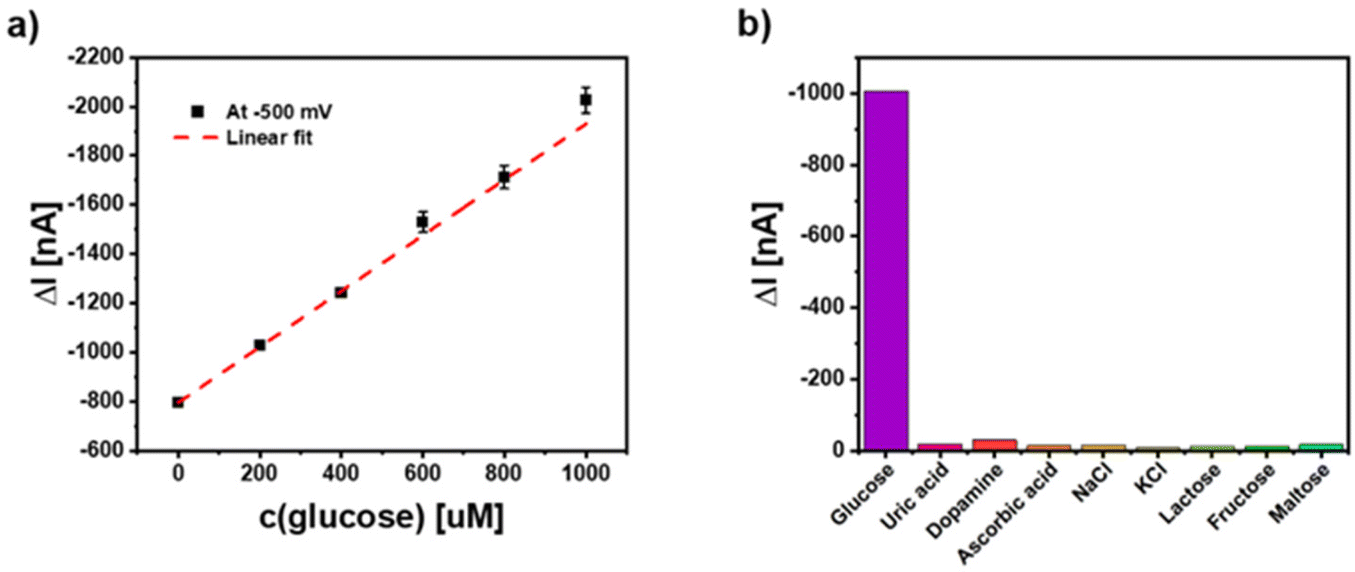 | ||
| Fig. 9 (a) Glucose detection using the electrodes coated with 5 layers of hybrid Ag/CeO2 NPs at U = −500 mV in PBS with 10% fetal bovine serum from Gibco with dissolved GOx (160 kDa, 1 mM, activity = 10 kU g−1) under white light illumination. (b) Selectivity performance of the PEC glucose measurements with different common interfering substances that have been added to the 10% fetal bovine serum at U = −500 mV. The concentration of the glucose is 1 mM and the concentration of the other analytes is 10 mM. | ||
Conclusions
We have systematically investigated the possibilities for enhancing the charge carrier generation and thus, photocurrent generation by combing the CeO2 NPs with Ag NPs. In this way the catalytic properties of CeO2 NPs have been combined with the surface plasmon excitation capability of Ag NPs in a photoelectrochemical detection system based on NP-modified gold electrodes. We exploit the photocurrent generation with the electrode-fixed CeO2 NPs and use the property of hydrogen peroxide conversion at this material. Such NP-electrode structures are limited with respect to the excitation wavelength. In a first approach we have mixed both types of NPs and studied the influence of the size of the metal NPs. In a second approach we succeed to show that a closer contact of the semiconductor with the metal NPs is essential for signal enhancement and in a third approach we have used hybrid NPs with the CeO2 directly grown on the Ag core. By fixing these hybrid NPs on a cysteamine modified gold electrode we have obtained the highest photocurrents with a visible light source. Additionally, it can be shown that the application of multilayers of such hybrid NPs can be applied for adjusting the sensitivity in a defined way.In order to demonstrate the involvement of surface plasmon state excitation inside the metal NPs in the photocurrent generation we have analyzed the photocurrent response wavelength dependent. Clearly the excitation of the metal part influences the photocurrent thus, implicating charge carrier transfer from/to the CeO2 NPs. The observed effects can be rationalized with the help of a plausible energy diagram for the reductive reaction pathway. The experiments also verify previous observations in combining a semiconductor with Au NPs and may open a new route for improved sensing strategies applying hybrid nanostructures on electrode surfaces.
In a final step we can also show that the excitation with visible light can be applied for the detection of a reaction partner of the CeO2 NPs – hydrogen peroxide. Compared to CeO2 NPs alone a much higher sensitivity for this test analyte can be obtained. As shown in Table 2, our assay also performs in the range of other H2O2 sensors.
| Read-out | Transducer | Nanomaterial | LOD | Linear range | Ref. |
|---|---|---|---|---|---|
| Electrical | Photoelectrochemical | CeO2/Ag NPs | 200 nM | 0.2–1000 μM | This work |
| CeO2/Co3O4 NPs | 86 μM | — | 43 | ||
| CeO2/Au NPs | 3 μM | 4 μM–2000 μM | 3 | ||
| CeO2/Co NPs | 3.7 μM | 5–10 μM | 44 | ||
| CeO2/MnO2 NPs | 0.07 μM | 45 | |||
| PbS NPs | 18 μM | 46 | |||
| CdS QDs | 0.06 μM | 19–356 μM | 47 | ||
| ZnO NPs | 0.27 μM | 0.1–100 μM | 48 | ||
| Au NPs | 2 μM | 30 μM–5 mM | 27 | ||
| Electrochemical | CeO2/graphene NPs | 1 μM | 2.8–160 μM | 49 | |
| CeO2 Pt/C NPs | 2 μM | 0.01–30 mM | 50 | ||
| CeO2/Pt NPs | 0.47 μM | 3.3–17.5 mM | 51 | ||
| CeO2/Au NPs | 7 μM | 0.05–2.5 mM | 52 | ||
| CeO2/polyaniline NPs | 50 mM | 53 | |||
| Optical | Fluorescence spectroscopy | CeO2/CDs NPs | 0.35 μM | 1.7 μM–2 mM | 54 |
| Colorimetric assay | CeO2/PDI NPs | 2.23 μM | 55 | ||
| Absorption spectroscopy | CeO2/C NWs | 0.69 μM | 1–100 μM | 56 | |
| CeO2/CePO4 NPs | 2.9 μM | 5–150 μM | 57 | ||
| CeO2/Cu2(OH)3Cl NPs | 50 μM | 0.02–0.05 mM | 58 | ||
| CeO2/TiO2 NPs | 3.2 μM | 5–100 μM | 31 |
Conflicts of interest
There are no conflicts to declare.Acknowledgements
This work was supported by the Cluster of Excellence ‘Advanced Imaging of Matter’ of the Deutsche Forschungsgemeinschaft (DFG) – EXC 2056 – project ID 390715994. SZ acknowledges funding by the Chinese Scholarship Council (CSC). NGB and VP acknowledge financial support from the Spanish Ministerio de Ciencia, Innovación y Universidades (MCIU) (RTI2018-099965-B-I00, AEI/FEDER, UE). ICN2 is supported by the Severo Ochoa program from Spanish MINECO (SEV-2017-0706) and is funded by the CERCA Programme/Generalitat de Catalunya. ZY acknowledges support from the National Natural Science Foundation of China (Grant No. 61871240).References
- B. Gao, X. Zhao, Z. Liang, Z. Wu, W. Wang, D. Han and L. Niu, Anal. Chem., 2020, 93, 820–827 CrossRef PubMed.
- N. Fu, L. Wang, X. Zou, C. Li, S. Zhang, B. Zhao, Y. Gao and L. Wang, Analyst, 2020, 145, 7388–7396 RSC.
- S. Zhao, M. Riedel, J. Patarroyo, N. Bastus, V. Puntes, Z. Yue, F. Lisdat and W. J. Parak, Nanoscale, 2021, 13, 980–990 RSC.
- M. Riedel, A. Ruff, W. Schuhmann, F. Lisdat and F. Conzuelo, Chem. Commun., 2020, 56, 5147–5150 RSC.
- S. Zhao, J. Völkner, M. Riedel, G. Witte, Z. Yue, F. Lisdat and W. J. Parak, Appl. Mater. Interfaces, 2019, 11, 21830–21839 CrossRef CAS PubMed.
- M. Riedel, G. Göbel, A. M. Abdelmonem, W. J. Parak and F. Lisdat, ChemPhysChem, 2013, 14, 2338–2342 CrossRef CAS PubMed.
- J. Tanne, D. Schafer, W. Khalid, W. J. Parak and F. Lisdat, Anal. Chem., 2011, 83, 7778–7785 CrossRef CAS PubMed.
- M. Riedel, S. Hölzel, P. Hille, J. Schörmann, M. Eickhoff and F. Lisdat, Biosens. Bioelectron., 2017, 94, 298 CrossRef CAS PubMed.
- K. Schubert, W. Khalid, Z. Yue, W. J. Parak and F. Lisdat, Langmuir, 2010, 26, 1395–1400 CrossRef CAS PubMed.
- N. Sabir, N. Khan, J. Völkner, F. Widdascheck, P. d. Pino, G. Witte, M. Riedel, F. Lisdat, M. Konrad and W. J. Parak, Small, 2015, 43, 5844–5850 CrossRef PubMed.
- I. Ibrahim, H. N. Lim, R. M. Zawawi, A. A. Tajudin, Y. H. Ng, H. Guo and N. M. Huang, J. Mater. Chem. B, 2018, 6, 4551–4568 RSC.
- N. Zhang, Z.-Y. Ma, Y.-F. Ruan, W.-W. Zhao, J.-J. Xu and H.-Y. Chen, Anal. Chem., 2016, 88, 1990–1994 CrossRef CAS PubMed.
- L. Neven, S. T. Shanmugam, V. Rahemi, S. Trashin, N. Sleegers, E. N. Carrión, S. M. Gorun and K. De Wael, Anal. Chem., 2019, 91, 9962–9969 CrossRef CAS PubMed.
- C. Stoll, C. Gehring, K. Schubert, M. Zanella, W. J. Parak and F. Lisdat, Biosens. Bioelectron., 2008, 24, 260–265 CrossRef CAS PubMed.
- C. Stoll, S. Kudera, W. J. Parak and F. Lisdat, Small, 2006, 2, 741–743 CrossRef CAS PubMed.
- M. M. Meirovich, O. Bachar, R. Nandi, N. Amdursky and O. Yehezkeli, ChemSusChem, 2021, 14, 5410–5416 CrossRef CAS PubMed.
- M. Riedel and F. Lisdat, ACS Appl. Mater. Interfaces, 2018, 10, 267–277 CrossRef CAS PubMed.
- M. Riedel, N. Sabir, F. W. Scheller, W. J. Parak and F. Lisdat, Nanoscale, 2017, 9, 2814–2823 RSC.
- W.-W. Zhao, J.-J. Xu and H.-Y. Chen, Chem. Rev., 2014, 114, 7421–7441 CrossRef CAS PubMed.
- S. Liu, Y. Jia, H. Dong, X. Yu, D.-P. Zhang, X. Ren, Y. Li and Q. Wei, Anal. Chem., 2020, 92, 10935–10939 CrossRef CAS PubMed.
- W.-W. Zhao, J. Wang, Y.-C. Zhu, J.-J. Xu and H.-Y. Chen, Anal. Chem., 2015, 87, 9520–9531 CrossRef CAS PubMed.
- Z. Yue, F. Lisdat, W. J. Parak, S. G. Hickey, L. P. Tu, N. Sabir, D. Dorfs and N. C. Bigall, ACS Appl. Mater. Interfaces, 2013, 5, 2800–2814 CrossRef CAS PubMed.
- W. Khalid, G. Göbel, D. Hühn, J.-M. Montenegro, P. Rivera Gil, F. Lisdat and W. J. Parak, J. Nanobiotechnol., 2011, 9, 46 CrossRef CAS PubMed.
- G. Wang, H. Wang, Y. Ling, Y. Tang, X. Yang, R. C. Fitzmorris, C. Wang, J. Z. Zhang and Y. Li, Nano Lett., 2011, 11, 3026–3033 CrossRef CAS PubMed.
- P. Varadhan, H.-C. Fu, D. Priante, J. R. D. Retamal, C. Zhao, M. Ebaid, T. K. Ng, I. Ajia, S. Mitra and I. S. Roqan, Nano Lett., 2017, 17, 1520–1528 CrossRef CAS PubMed.
- J. Zhang, L. Tu, S. Zhao, G. Liu, Y. Wang, Y. Wang and Z. Yue, Biosens. Bioelectron., 2015, 67, 296–302 CrossRef CAS PubMed.
- Z. Shuang, Z. Jun, L. Zhengping, Z. Peixin and L. Yunxiao, Microchim. Acta, 2017, 184, 1–10 CrossRef.
- S. Zhao, Z. Li, Y. Li, J. Yu, G. Liu, R. Liu and Z. Yue, J. Photochem. Photobiol., A, 2017, 342, 15–24 CrossRef CAS.
- E. Murugan, S. S. Kumar and A. Raman, Adv. Mater. Proc., 2018, 3, 112–117 CrossRef.
- K. Negi, A. Umar, M. S. Chauhan and M. S. Akhtar, Ceram. Int., 2019, 45, 20509–20517 CrossRef CAS.
- K. Saravanakumar, M. M. Ramjan, P. Suresh and V. Muthuraj, J. Alloys Compd., 2016, 664, 149–160 CrossRef CAS.
- M. Mittal, A. Gupta and O. P. Pandey, Sol. Energy, 2018, 165, 206–216 CrossRef CAS.
- D. Van Dao, T. T. D. Nguyen, H.-Y. Song, J.-K. Yang, T.-W. Kim, Y.-T. Yu and I.-H. Lee, Mater. Des., 2018, 159, 186–194 CrossRef CAS.
- L. Wu, S. Fang, L. Ge, C. Han, P. Qiu and Y. Xin, J. Hazard. Mater., 2015, 300, 93–103 CrossRef CAS PubMed.
- S. A. Mahyoub, A. Hezam, F. A. Qaraah, K. Namratha, M. B. Nayan, Q. A. Drmosh, D. Ponnamma and K. Byrappa, ACS Appl. Energy Mater., 2021, 4, 3544–3554 CrossRef CAS.
- J. Gu, H. Liu, T. Peng, S. Li, L. Xu, J. Zhang and L. Zhang, ACS Appl. Nano Mater., 2022, 5, 4972–4982 CrossRef CAS.
- T. Jayalakshmi, S. A. Prashanth, F. A. Alharthi and G. Nagaraju, J. Electron. Mater., 2020, 49, 7568–7580 CrossRef.
- N. G. Bastus, F. Merkoci, J. Piella and V. Puntes, Chem. Mater., 2014, 26, 2836–2846 CrossRef CAS.
- N. G. Bastús, J. Piella, S. Perez, J. Patarroyo, A. Genc, J. Arbiol and V. Puntes, Appl. Mater. Today, 2019, 15, 445–452 CrossRef.
- F. Al-Marhaby and R. Seoudi, World J. Nano Sci. Eng., 2016, 6, 29 CrossRef.
- J. Patarroyo, J. A. Delgado, F. Merkoçi, A. Genç, G. Sauthier, J. Llorca, J. Arbiol, N. G. Bastus, C. Godard, C. Claver and V. Puntes, Sci. Rep., 2019, 9, 18776 CrossRef CAS PubMed.
- J. Hühn, C. Carrillo-Carrion, M. G. Soliman, C. Pfeiffer, D. Valdeperez, A. Masood, I. Chakraborty, L. Zhu, M. Gallego, Y. Zhao, M. Carril, N. Feliu, A. Escudero, A. M. Alkilany, B. Pelaz, P. d. Pino and W. J. Parak, Chem. Mater., 2017, 29, 399–461 CrossRef.
- X. Cao, S. Zhao, X. Liu, X. Zhu, Y. Gao and Q. Liu, Anal. Bioanal. Chem., 2022, 414, 4767–4775 CrossRef CAS PubMed.
- J. Lian, P. Liu, C. Jin, Q.-Y. Liu, X. Zhang and X. Zhang, ACS Sustainable Chem. Eng., 2020, 8, 17540–17550 CrossRef CAS.
- H. Wang, W. Yang, X. Wang, L. Huang, Y. Zhang and S. Yao, Sens. Actuators, B, 2020, 304, 127389 CrossRef CAS.
- Q. Han, H. Wang, D. Wu and Q. Wei, Biosens. Bioelectron., 2021, 173, 112803 CrossRef CAS PubMed.
- N. Khaliq, M. A. Rasheed, M. Khan, M. Maqbool, M. Ahmad, S. Karim, A. Nisar, P. Schmuki, S. O. Cho and G. Ali, ACS Appl. Mater. Interfaces, 2021, 13, 3653–3668 CrossRef CAS PubMed.
- W. Liu, W. Zhan, X. Jia, Q. Liu, R. Chen, D. Li, Y. Huang, G. Zhang and H. Ni, Appl. Surf. Sci., 2019, 480, 341–348 CrossRef CAS.
- E. Rezvani, A. Hatamie, M. Berahman, M. Simchi, S. Angizi, R. Rahmati, J. Kennedy and A. Simchi, J. Electrochem. Soc., 2019, 166, H3167–H3174 CrossRef CAS.
- A. Uzunoglu and H. H. Ipekci, J. Electroanal. Chem., 2019, 848, 113302 CrossRef CAS.
- M. Guler, V. Turkoglu, A. Kivrak and F. Karahan, Mater. Sci. Eng., C, 2018, 90, 454–460 CrossRef CAS PubMed.
- W. Zhang, G. Xie, S. Li, L. Lu and B. Liu, Appl. Surf. Sci., 2012, 258, 8222–8227 CrossRef CAS.
- A. A. Ansari, G. Sumana, R. Khan and B. D. Malhotra, Nanotechnology, 2009, 9, 4679–4685 CAS.
- Z. Yang, Y. Liu, C. Lu, G. Yue, Y. Wang, H. Rao, W. Zhang, Z. Lu and X. Wang, J. Alloys Compd., 2021, 862, 158323 CrossRef CAS.
- H. Liu, Y. He, N. Li, Z. Liu, X. Zhang, X. Zhang and Q. Liu, ACS Appl. Bio Mater., 2020, 3, 2499–2506 CrossRef CAS PubMed.
- W. Dong and Y. Huang, Microchim. Acta, 2019, 187, 11 CrossRef PubMed.
- G. Vinothkumar, A. I. Lalitha and K. Suresh Babu, Inorg. Chem., 2019, 58, 349–358 CrossRef CAS PubMed.
- N. Wang, J. Sun, L. Chen, H. Fan and S. Ai, Microchim. Acta, 2015, 182, 1733–1738 CrossRef CAS.
Footnote |
| † Electronic supplementary information (ESI) available. See DOI: https://doi.org/10.1039/d2nr01318e |
| This journal is © The Royal Society of Chemistry 2022 |