
Controlling reaction paths for ultra-fast growth of inorganic nanowires floating in the gas phase†
Richard S.
Schäufele
 ab,
Miguel
Vazquez-Pufleau
b,
Afshin
Pendashteh
b and
Juan J.
Vilatela
*b
ab,
Miguel
Vazquez-Pufleau
b,
Afshin
Pendashteh
b and
Juan J.
Vilatela
*b
aDepartment of Applied Physics, Universidad Autónoma de Madrid, Cantoblanco 28049, Madrid, Spain
bIMDEA Materials, Madrid 28049, Spain. E-mail: juanjose.vilatela@imdea.org; Tel: +34 915493422
First published on 10th December 2021
Abstract
Synthesis of inorganic nanowires/nanotubes suspended in the gas through floating catalyst chemical vapour deposition (FCCVD) produces exceptional growth rates of 5–1000 micron per second, several orders of magnitude faster than conventional substrate processes. It leads to nanowire lengths >100 microns and thus to the possibility of direct assembly into freestanding macroscopic networks as a continuous process. This work studies the different reaction paths controlling conversion and selectivity in FCCVD applied to the synthesis of silicon nanowires (SiNWs) from silane, grown through an aerosol of gold catalyst nanoparticles. There are two main competing reactions: catalysed growth of SiNWs and non-catalysed formation of amorphous Si nanoparticles. The mass fraction of the two populations can be precisely determined by XRD and Raman spectroscopy, enabling high-throughput screening of reaction parameter space. The experimental data and accompanying analytical model show that selectivity is kinetically controlled by the ratio of precursor/hydrogen carrier gas, through its inhibition of the pyrolisis of silane into silylene. In contrast, the rate of SiNW growth is largely unaffected by hydrogen and not limited by precursor availability. These results provide a framework to describe the kinetics of nanomaterials growth by FCCVD.
1 Introduction
One-dimensional (1D) inorganic nanostructures are interesting materials with exceptional morphological anisotropy. They can combine a high degree of crystallinity extending over very long domain sizes longitudinally, with quantized electronic structure and enormous surface-to-volume ratio as a result of their nanosized diameter. As macroscopic ensembles, 1D nanomaterials form percolated networks that can minimise charge transport resistance1 and exhibit high toughness,2 amongst other properties that make nanostructured networks of interest for application as electrodes for energy storage and conversion.3–5 Implementation in these and many other envisaged applications requires large amounts of 1D nanostructures, typically above thousands of tonnes per year, thus calling for processes that are scalable and have high selectivity towards the crystallinity and purity of the final material.The most common methods for nanowire (NW) synthesis include wet-chemical methods, such as supercritical fluid–liquid–solid (SFLS) growth,6 top-down methods, such as electrochemical etching,7,8 and gas-phase processess based on the vapor–liquid–solid (VLS) growth mode.9 These methods have different merits according to their target application, and different challenges for scale-up. Top-down methods, for example, are constrained by the size and shape of the crystalline monolith from which the excess material is removed. Wet-chemical methods are batch processes, with throughput of NWs per batch in the range of around 100 mg, and require numerous additional processing steps to harvest the 1D nanostructures.10 The resulting NWs produced by wet-chemical methods often have moderate purity,11 with a relatively high surface contamination reminiscent of the carbonaceous precursor species and solvents used in the reaction.12
Gas-phase processes for synthesis of nanomaterials are highly scalable,13 enable large control over their chemistry and morphology, and are applicable to an enormous library of different nanomaterials.9 For nanowires and nanotubes (NT), their synthesis is commonly conducted through thermo-catalytic decomposition of precursors and incorporation into a catalyst resting on a substrate, generally following the well-known VLS mechanism.14
In a particularly interesting synthesis mode, the catalyst for NW growth is not supported on a substrate but floating in the gas stream, as demonstrated for carbon nanotubes (CNTs),15 boron nitride nanotubes (BNNT),16 III–V semiconductor nanowires,17 and more recently silicon nanowires (SiNWs).18 Growth through floating catalyst chemical vapour deposition (FCCVD) eliminates the need for substrates, enabling a continuous process where nanowires are directly assembled into macroscopic solids from the gas phase.15 The solids produced by this method have shown bulk mechanical, electrical and thermal properties in the high-performance range and above reference engineering materials.19
Very importantly, growth of nanowires through FCCVD occurs under conditions that are significantly different from substrate-based CVD. For instance, the FCCVD process is in a flow-through reactor (Fig. 1a), instead of a batch reactor, thus, mixing of the aerosol of catalyst nanoparticles and the precursor gas is essentially instantaneous and homogeneous, avoiding precursor depletion zones. As a consequence, at similar process conditions, floating catalyst particles are exposed to higher effective precursor concentrations resulting in increased catalytic activity and lower diffusion bottlenecks. These are further enhanced by unlocking higher growth temperatures, which are not inhibited anymore by substantial precursor consumption from undesired thin film growth on the substrate.17 Overall, atmospheric FCCVD leads to 20–1000 times faster growth rates than substrate processess,18,20 and produces high aspect ratios for nanowires (>200, e.g.Fig. 1b and c) and for nanotubes. This enables short residence times only in the order of <15 seconds, in contrast with common reaction times of >20 minutes for substrate-based processes.
 | ||
| Fig. 1 Synthesis of SiNWs by FCCVD. (a) A schematic of the FCCVD reactor, consisting of a tubular reactor with gas inlets, a nanoparticle generator, heated CVD chamber and collection zone. SiNWs grow via the VLS mechanism through thermocatalytic decomposition of SiH4 assisted by an aerosol of Au nanoparticles. (b) SEM micrograph of network of SiNWs synthesized via FCCVD; Au nanoparticles are clearly visible (white dots) and match respective SiNW diameters. (c) High growth rate of FCCVD synthesis results in long SiNWs with typical average lengths of ≥3 μm and top lengths of around 12 μm, as shown in this SEM micrograph. | ||
Of particular interest is to determine the factors that control selectivity and conversion in the growth of NW by FCCVD. For CNTs, BNNTs, and III–V semiconductor NWs, high-purity materials are typically produced under very dilute synthesis conditions and low conversion, whereas reaction conditions for high conversion and/or high throughput often produce formation of a large fraction of soot-like nanoparticles and other impurities. Under conditions of high selectivity (>95% nanowire volume fraction) in GaAsNW synthesis, for example, conversion is estimated at around 0.25%.21–23 Conversion in FCCVD synthesis of carbon nanotubes ranges between 0.07–10%,24 but at high conversions typically with more than 10% volume fraction of carbonaceous impurities.
This paper sets out to study growth of 1D nanostructures by FCCVD using SiNWs as a model system. Through direct measurements of reaction throughput and sample purity-crystallinity, the results lead to maps of conversion and selectivity. These clarify the role of hydrogen, which besides acting as a “carrier” gas suppresses non-catalysed growth of solid silicon from late derivates in silane pryolisis. The experimental results are rationalised with a kinetic model describing the two dominant reactions.
2 Methods
Synthesis of SiNWs is performed in a customized flow-through FCCVD reactor. As shown schematically in Fig. 1a, it consists of a tubular reactor with gas inlets, a nanoparticle generator, heated CVD chamber and collection zone. The catalyst nanoparticle generator produces Au nanoparticles through thermal evaporation of Au at temperatures of approximately 1500 °C, which are transported to the reactor chamber using N2 as carrier gas. H2 and SiH4 are introduced through separate ports. The CVD chamber is a vertical tube furnace with a reactor tube of 10 cm outer diameter. Samples are collected by directly depositing them on a filter paper connected to a vacuum pump.This work focuses on the role of the carrier gas in the conversion and selectivity in the decomposition of SiH4 in the presence of Au. We experimented with reaction conditions that featured SiH4 molar fractions of 0–3%, H2 molar fractions of 28–72% and the remaining part being N2. Total gas flow rate ranged from 4slm to 8slm and were controlled with OMEGA FMA5500A-type mass flow controllers and Bronkhorst Coriolis flow controllers. Other synthesis parameters were fixed: reactor pressure at 900 mbar, reaction zone temperature of 650 °C, and Au catalyst nanoparticles average diameter of 22.3 nm ± 8.5 nm. Residence times are calculated from the total gas flow traversing the hot zone of the reactor tube, taken as 30 cm. They were in the range of 5–13 seconds for the experiments in this study.
SiNW samples were studied with a scanning electron microscope (SEM; FEI Helios NanoLab 600i) in order to determine average diameter of SiNWs and AuNPs, average length and average aspect ratio. These were obtained from image analysis of SEM micrographs of over 168 different SiNWs (see ESI†), utilizing the software ImageJ. High resolution transmission electron microscopy (HRTEM) images, EDX profiles and SAED patterns were taken in a FEI Talos F200X operating at 80 kV. Raman spectroscopy was carried out in a Renishaw inVia micro-Raman spectrometer with a laser wavelength of 532 nm (2.33 eV) using 50× objectives and a low power configuration in order to avoid heating effects and sample damage. Samples were weighed using a Precisa ES 125SM analytical balance. These samples were freestanding sheets directly removed from the paper filter. X-ray diffraction data were collected at the NCD-SWEET, the wide-angle/small-angle X-ray scattering (WAXS/SAXS) beamline of the Spanish synchrotron ALBA. Scattering of the samples was collected at a radiation wavelength of λ = 1.0 Å. Prior to scattering collection, the sample holder position was calibrated using silver behenate (AgBh) for SAXS and chromium oxide (Cr2O3) for WAXS. The patterns were first corrected for the background scattering and then analyzed using DAWN software (v. 2.20), obtaining radial profiles after azimuthal integration.
Mathematical fitting of experimental data using the proposed kinetic models was done by iteration, using a supervised minimum square methodology. Details are included in ESI.†
3 Results
3.1 Reaction selectivity
SiNWs are grown through the thermocatalytic decomposition of SiH4 in the presence of an aerosol of Au nanoparticles in a flow-through reactor. The process is assumed to occur through formation of liquid Au–Si eutectic nanoparticles, which upon supersaturation lead to rapid growth of high aspect SiNWs through the VLS mechanism, but floating in the gas stream. For instance, in Fig. 2a–d we present details of the microstructure and composition of a freestanding sample of SiNWs produced at a SiH4:H2:N2 molar ratio of 2.2![[thin space (1/6-em)]](https://www.rsc.org/images/entities/char_2009.gif) :62.2:35.6. Under these conditions the samples have extremely high purity, consisting almost entirely of SiNWs of large aspect ratios (up to 250), few kinks and virtually no contamination. The average diameter of Au catalyst nanoparticles (21.1 ± 7.5 nm), located at SiNW tips, closely matches the average nanowire diameter (23.0 nm ± 7.1 nm) indicating that growth occurs through the classic VLS mechanism without significant tapering. Apart from this, in-depth TEM analysis (Fig. 2b and c) shows the monocrystalline nature of such SiNWs, which predominantly grow into the <110> direction. After the synthesis process, once taken out of the FCCVD reactor and exposed to air, a native oxide layer of approximately 1.5–2.5 nm is formed on the nanowire surface.25 We note the distinctive yellowish colour of this type of high-purity samples, as shown in the inset of Fig. 2a.
:62.2:35.6. Under these conditions the samples have extremely high purity, consisting almost entirely of SiNWs of large aspect ratios (up to 250), few kinks and virtually no contamination. The average diameter of Au catalyst nanoparticles (21.1 ± 7.5 nm), located at SiNW tips, closely matches the average nanowire diameter (23.0 nm ± 7.1 nm) indicating that growth occurs through the classic VLS mechanism without significant tapering. Apart from this, in-depth TEM analysis (Fig. 2b and c) shows the monocrystalline nature of such SiNWs, which predominantly grow into the <110> direction. After the synthesis process, once taken out of the FCCVD reactor and exposed to air, a native oxide layer of approximately 1.5–2.5 nm is formed on the nanowire surface.25 We note the distinctive yellowish colour of this type of high-purity samples, as shown in the inset of Fig. 2a.
 | ||
| Fig. 2 Two distinct FCCVD-grown SiNW samples are presented. Sample A (a–d) which has been produced at a SiH4:H2:N2 molar ratio of approximately 2.2:62.2:35.6, respectively, and sample B (e–h) which has been produced at a SiH4:H2:N2 molar ratio of approximately 2.7:54:43.3, respectively. (a) and (e) show low magnification SEM micrographs and insets of respective complete samples (scale bar equals 1 cm). While sample A has a yellowish tone and a pristine network of SiNWs where Au seed particles are easily spotted, sample B is dark brown and SiNWs are heavily polluted with almost no visible Au nanoparticles. (b) and (f) are high resolution TEM micrographs with insets of respective EDX profiles showing Si content. We also present corresponding SAED patterns in (c) and (g). Sample A consists of clean and monocrystalline SiNWs. In contrast, sample B features crystalline SiNWs that are heavily contaminated with a-Si which is underlined by the combination of amorphous rings and crystalline interference points in the SAED pattern (g).( d) and (h) show normalized Raman spectra of sample A and B including deconvoluted peaks. | ||
The SiNW morphology and overall purity of materials synthesised in this FCCVD mode depends on various synthesis parameters, but in our exploration of parameter space so far, we have observed a strong dependence on the molar fraction of H2, N2 and SiH4. As an example, in Fig. 2e–h we show compositional information of a sample produced with a higher SiH4 molar ratio and a lower H2 molar ratio (SiH4:H2:N2 molar ratio of approximately 2.7:54:43.3), but otherwise under nominally identical synthesis conditions in terms of catalyst concentration and size, reaction temperature and pressure. Residence time is also similar, at 6.9 s and 8.4 s for the samples in Fig. 2a and e, respectively. The second sample has a dark brown colour and contains a high degree of impurities in addition to SiNWs. These impurities are irregular-shaped particulates, either aggregated as clusters trapped between the SiNWs network or coating the SiNW surface (Fig. 2e). Indeed, we observe a substantial increase in apparent nanowire diameter (44.0 nm ± 15.1 nm) in this sample, while average size of Au seed nanoparticles remains at approximately 24.4 nm ± 6.8 nm. Via EDX analysis and selected area electron diffraction (SAED) we find the impurities to be amorphous silicon (a-Si) (Fig. 2f–g).
3.2 High-throughput screening of reaction selectivity
In order to study in detail the effect of synthesis parameters on selectivity towards SiNW growth, we first developed a method for rapid characterisation of samples. Sample colour is clearly indicative of purity (Fig. 2 and 3): the brighter the sample colour the less the a-Si contamination and therefore, the higher the crystallinity. This is helpful for rough screening of samples, but is not a direct measure of sample composition. Instead, we use Raman spectroscopy, which combines minimal sample preparation, fast measurement time and a relatively large probe size (around 3 microns). Indeed, Raman spectroscopy is a common choice for rapid analysis and more recently for autonomous research systems.26 | ||
| Fig. 3 Crystallinity is plotted against H2 molar fraction and SiH4 molar fraction for various FCCVD-grown samples. Colour coding of data points is maintained throughout Fig. 3, 4 and Fig. S4† in order to simplify tracking of individual experiments on the various presented plot formats. Insets highlight respective sample colours. | ||
The compositional difference between SiNW samples are clearly visible in their Raman spectra. The spectrum for the high purity sample (Fig. 2d) has a sharp peak corresponding to the 1st order TO phonon of crystalline Si (c-Si), a small peak at 483 cm−1 found in SiNWs27 (Fig. S1†), and a very weak peak at 496 cm−1 corresponding to the 1st order TO phonon of a-Si (Fig. S1†). The same three peaks are also present in the low purity sample (Fig. 2h), however, the a-Si peak is significantly more pronounced. The higher abundance of a-Si is in line with SEM and TEM analysis.
We found a direct correlation between the relative intensity of the Raman peaks for a-Si and c-Si, and the overall sample purity determined by electron microscopy (Fig. S2†). Furthermore, because the impurities produced in this temperature range are amorphous, a Raman-derived nanowire purity can be obtained which is directly correlated with crystalline mass fraction, (Fig. S6†).28 Hence, sample crystallinity (purity) can be quantitatively determined from the Raman spectra, calculated for example as:
 | (1) |
Very importantly, this crystallinity parameter ![[C with combining overline]](https://www.rsc.org/images/entities/i_char_0043_0305.gif) is indicative of the selectivity of the FCCVD reaction. Since the weighted Raman intensities are proportional to the mass fraction of the different phases (Fig. S6†), C is equivalent to the fraction of material synthesised through growth catalysed by Au.‡
is indicative of the selectivity of the FCCVD reaction. Since the weighted Raman intensities are proportional to the mass fraction of the different phases (Fig. S6†), C is equivalent to the fraction of material synthesised through growth catalysed by Au.‡
The approach is demonstrated in Fig. 3. It shows the crystallinity and colour of SiNW samples produced at different SiH4:H2:N2 molar fractions plotted against C. Crystallinity increases with a higher content of H2 and a lower content of SiH4, reaching a plateau at approximately 98% C. This is consistent with SEM analysis of the samples, presented in Fig. S2,† although above ![[C with combining macron]](https://www.rsc.org/images/entities/i_char_0043_0304.gif) = 93% a-Si cannot be detected by SEM.
= 93% a-Si cannot be detected by SEM.
3.3 Mapping SiNW growth
Equipped with gravimetric measurements and a crystallinity metric we then study the envelope of conversion and selectivity of the reaction as a function of the composition of the gas mix. Here, we consider conversion as the mass ratio of input SiH4 over collected SiNWs, ignoring possible losses to the reactor walls or through the vacuum system. Effectively, this represents a lower bound for the actual conversion of the FCCVD reaction, but nevertheless reflecting the dependence on gas composition of interest for this study.A large space of synthesis conditions was found to lead to successful growth of samples with predominantly SiNWs. The most relevant to understand the relation between selectivity and conversion are summarised in Fig. 4. The colour codes represent different experimental sets, for example, at constant total gas flow rate (yellow spheres), constant flow rate of hydrogen and nitrogen gas (green spheres), or constant molar ratio of SiH4/H2 (red spheres).
 | ||
| Fig. 4 Envelope of selectivity and conversion for SiNW growth by FCCVD under different molar fractions of precursor and other gases. (a) Plot of crystallinity against H2 molar fraction and SiH4 molar fraction for all relevant experiments. (b) Silane conversion against H2 molar fraction and SiH4 molar fraction. (c) Relation between crystallinity and conversion, showing an exponential decay in crystallinity with increasing conversion. (d) Map of conversion and crystallinity for different molar ratios of SiH4/H2, showing that both dilution and the presence of H2 are required for growth of SiNWs. | ||
Fig. 4a presents a plot of crystallinity for different molar fractions of SiH4 and H2 (the remaining fraction is N2). It shows that conditions leading to high crystallinity correspond to a low SiH4 concentration and/or high H2 content. For instance, high crystallinity of above 95% is only achieved for SiH4 molar fractions below 2%, and requiring between 34% and 64% H2. In other words, selectivity is favoured under dilute conditions in hydrogen.
Fig. 4b presents the conversion data for the same reaction conditions. The data follow the opposite behaviour. Conversion increases with increasing SiH4 molar fraction, which is expected, but H2 has also a strong effect. The yellow datapoints, for example, show that replacement of H2 with N2 at constant SiH4 molar fraction increases conversion from 0.13% to 0.56%.
The balance between crystallinity and conversion is more clearly observed in Fig. 4c. It shows a clear drop in crystallinity with increasing conversion, with the data falling on an exponential decay curve. The curve represents the limits of conversion and selectivity for different combinations of SiH4:H2:N2 fractions. Its absolute values depend on specific details of the synthesis reactor, but the trend is inherent to the FCCVD reaction.
Given the observed dependence of the reaction on the fractions of both SiH4 and H2, it is insightful to analyse a plot of conversion against the molar ratio of SiH4/H2, as shown in Fig. 4d. In this representation the values of crystallinity define areas in the two-dimensional graph. For example, the region of crystallinity above 88% stretches up to a conversion of approximately 0.25% and corresponds to a low SiH4/H2 ratio. Conversely, a high SiH4/H2 ratio increases conversion almost linearly to 0.6%, but reduces crystallinity below 70%.
4 Discussion
The results in the preceding section show that the selectivity and conversion are controlled by the ratio of SiH4/H2. Higher dilution favours growth of crystalline SiNWs, but hydrogen is required for the reaction. In its absence, virtually only a-Si nanoparticles are formed (Fig. S6†).Solid silicon is a stable product of the FCCVD reaction; it has a lower chemical potential μsolid than silicon as a gas and than the eutectic with Au.30 This thermodynamic product can be formed via two different mechanisms: VLS or vapor–solid (VS) growth. The VLS route is catalysed by gold and leads to growth of crystalline NWs, with the lower activation energy (reported to be between 17.5–22 kJ mol−1).31,32
The main competing mechanism is non-catalyzed formation of solid Si through direct deposition as particulates or a coating on nascent nanowires. The corresponding activation energy is reported to be 29–38 kJ mol−1 and thus higher than what is required in the first step of VLS growth. The selectivity of the process could potentially be affected by hydrogenation/passivation of active surfaces at SiNWs and a-Si particles in the presence of H2 gas, which could change the activation energy for the catalysed and non-catalysed reactions33,34 and thus favour one of the products. This is unlikely though. The small SiH4/H2 molar ratios used in our study imply that both the catalyst and nascent NWs are essentially in a H2-rich atmosphere for all reaction conditions.
Instead, the selectivity of the process is controlled by the effect of hydrogen on the kinetics of the two reactions. And its effect is particularly prominent because of the high collision rate between SiHx molecules compared to the rate of arrival on Au catalyst nanoparticles.
For both the VLS and VS routes, the conversion of SiH4 into solid Si occurs through silane derivates. As a product of the reaction, hydrogen is known to affect the reversible decomposition reactions of SiH4 into silane derivates:35
 | (2) |
We expect that early derivates can take part in the VLS route, for example via further decomposition at the Au catalyst particle. In contrast, non-catalysed formation of solid Si from silane pyrolisis is likely to require late derivates. They form via silane pyrolysis by undergoing a series of polymerization reactions29,36,37 which release hydrogen. Therefore, based on Le Chatelier's principle, higher hydrogen availabilty is expected to reduce reaction rate. Indeed, the kinetic constants reported for non-catalised formation of nanoparticles are a factor of 2 lower for early reaction times (conversions between 3–35%) than for later reaction conditions (conversion between 39–75%).35 Thus, the role of hydrogen in the selectivity of the process is in avoiding the VS route through suppression of extended SiH4 decomposition. This is schematically shown in reaction (3), where multiple lines indicate enhanced reaction pathways:
 | (3) |
If selectivity is governed by the suppression of a-Si, this implies that the reaction conditions leading to an increase in conversion simply produce more a-Si in addition to SiNWs. This is indeed the case. From electron microscopy analysis of samples covering a wide range of crystallinity and reaction conversion values we find the number density of SiNWs to remain fairly constant (Fig. S4d†). This is a consequence of the catalyst activity being close to 100% and largely independent of SiH4/H2 ratio (see ESI†).
4.1 Kinetic model
The proposed control over reaction selectivity and conversion can be related to the experimental results through a simplified model of the kinetics of the two reactions occurring in the FCCVD process.In order to simplify the problem and constrain its mathematical complexity the following assumptions are made:
(a) The experimental reactor is well described by the plug flow reactor model, i.e. there is perfect mixing in the radial direction but no mixing along the axial direction.
(b) The reactor is considered isothermal, equal to the setpoint of the furnace.
(c) The reaction goes to completion until exhaustion of silane. This is supported by kinetic estimation showing that even in the case of inhibited reaction, more than 99% percent of the reaction is over after the first 0.5 s. In contrast, the lower bound of residence time in the reactor is about 5 s.
(d) The losses to the reactor walls or formation of side-products, such as sub-2 nm clusters,37 do not affect the ratio of the two primary measurable products i.e. nanowires and amorphous nanoparticles which are described by eqn (1) and expressed as a function of mass in eqn (5)
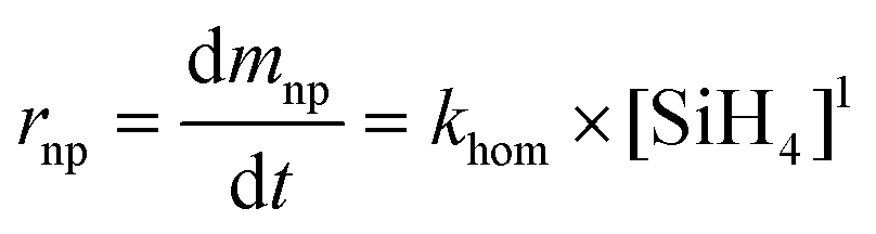
Under these assumptions, the rate of disappearance of silane is equal to the sum of the rate of formation of nanoparticles and nanowires:
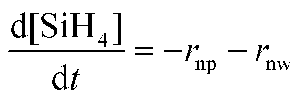 | (4) |
Then crystallinity C can be obtained by solving the following equation:
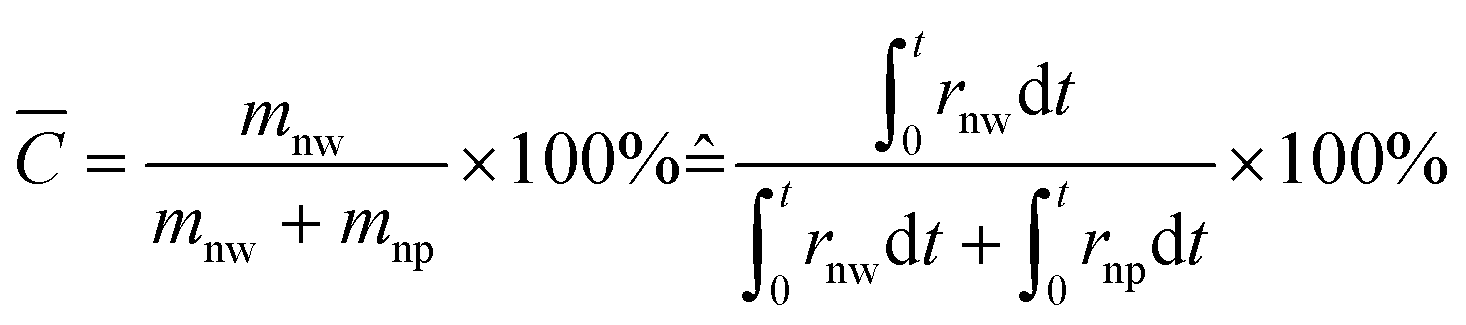 | (5) |
The upper bound t of the integral is until completion based on the assumption in (c).
A very approximate expression to describe the growth rate of silicon nanowires is reported in the literature for synthesis catalysed by Au nanoparticles supported on a substrate.38 It relates longitudinal growth velocity (vnw, in nm) to silane molar fraction (xSiH4,percentage), total pressure (Ptot, in mbar) and temperature (T, in K) by:
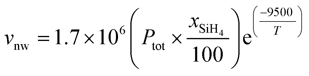 | (6) |
It follows that the mass production rate of nanowires (ṁnw) is given by multiplying its linear growth velocity vnw times its cross sectional area, times the total number of nanowires Nonw and density of silicon ρ:
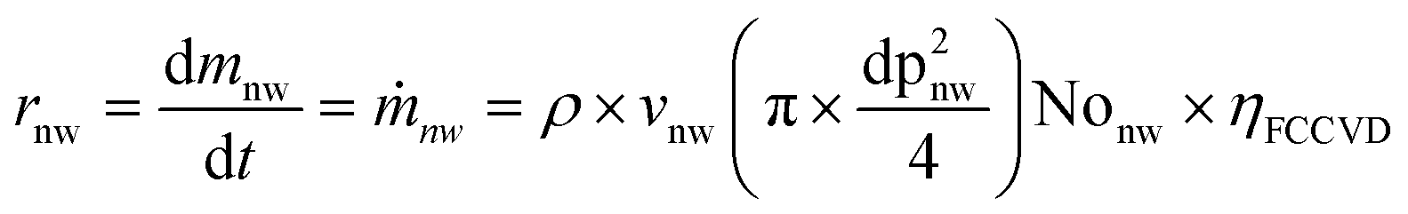 | (7) |
However, eqn (6) and (7) predict indefinite growth with increasing precursor availability, which is adequate to describe growth for substrate CVD under low pressure (<1.6 mbar, equivalent to around 0.18 silane molar ratio). In the synthesis of 1D nanomaterials by FCCVD growth rate is exceptionally fast, between approx. 1 μs−1 for nanowires and 100000 μs−1 for nanotubes, and may thus be limited by other factors. Indeed, we find that SiNW aspect ratio is very high for all synthesis conditions and has a very weak dependence on hydrogen concentration (Fig. S4†). Therefore, eqn (7) is valid up to a silane saturation concentration [SiH4]sat.
The nanoparticle formation rate is taken as the kinetics of homogeneous nucleation from Hogness et al.,39 who derived this kinetic expression and constant based on pressure changes in a reactor fed with high purity silane.
 | (8) |
 | (9) |
Eqn (4) and (9) have been succesfully used in studies of competing reactions during nanoparticle growth,34 but not under variable hydrogen concentration. This can be included in the model by considering a simple silicon nanoparticles formation mechanism following the reaction:
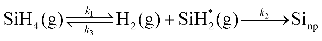 | (10) |
And thus
 | (11) |
However, this expression is a function of the concentration of the silylene radical  , which is not known and very difficult to measure due to its high reactivity and transient nature. Therefore, we reformulate the rate expression of silicon nanoparticle synthesis as a function of more easily measurable variables. The first step is to formulate the rate of formation of the silylene intermediate
  , which is given by:
 | (12) |
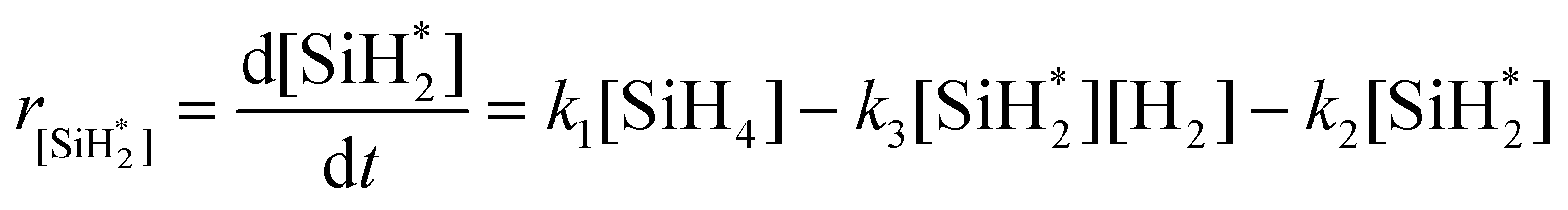
Using the pseudo steady state hypothesis, which assumes that the intermediate radical  is consumed as quickly as it is generated and therefore its concentration remains constant during the reaction, we obtain:
 | (13) |
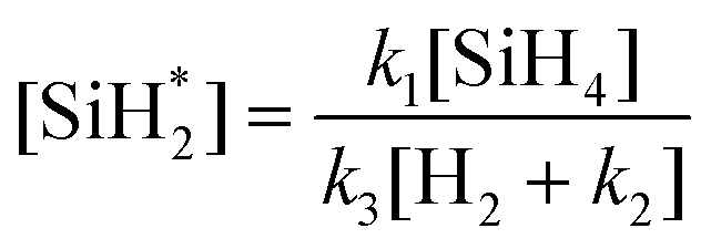 | (14) |
 | (15) |
When no hydrogen is present this expression reduces the case where the rate limiting step is the formation of silylene.29,40
Through an iterative process, we use the growth rate eqn (15), (7) and (4) to fit the experimental data for selectivity as a function of precursor and hydrogen concentration, with three unknown parameters: the factor related to supression of nanoparticle formation (k3/k2), the growth enhancement parameter for FCCVD growth (ηFCCVD), and the silane saturation concentration above which it does not limit growth rate([SiH4sat]). As shown in Fig. 5, there is good agreement between the experimental and calculated data (see supplementary video of 3D plot). The mathematical description of inhibition of nanoparticles formation at higher hydrogen concentration is well described by the homogeneous nucleation inhibition factor. Similarly, the decline of nanowire presence at higher silane concentration is in agreement with the proposed saturation effect.
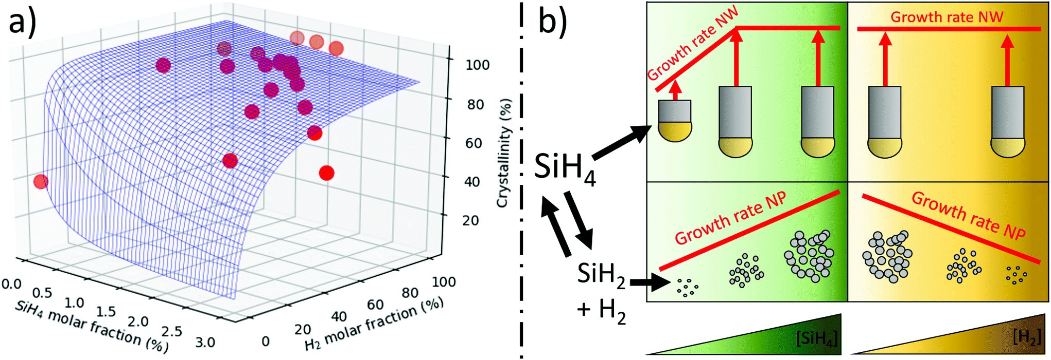 | ||
| Fig. 5 (a) Crystallinity predicted from mathematical model which includes the synthesis of nanoparticles with its hydrogen inhibition dependence and the synthesis of silicon nanowires with a proposed silane transport limitation. (b) Simplified mechanistic pathway for the formation of NWs and NPs. The effect of SiH4 and H2 is presented schematically. Higher SiH4 increases growth rate of both NWs and NPs, but NW growth rate plateaus at a silane saturation concentration. Hydrogen does not seem to have any effect on NW growth rate but does inhibit NP formation. | ||
From the fitting, we obtain that the a-Si nanoparticle suppression term is k3/k2 = 1.4 × 107 cm3 g−1. The only report found on the kinetics of silane decomposition for nanoparticle growth by White et al.35 has a large scatter in kinetic constants, preventing a comparison with the value obtained in this work but in qualitative agreement with our results. The nanowire growth enhancement factor ηFCCVD = 25, which is a factor of 25 times higher than proposed for substrate-grown SiNWs.38 The saturation precursor concentration [SiH4sat] gives 0.05% molar ratio, which is equivalent to a collision rate with catalyst particles of 109 Si-atoms per s. This is 1/100th relative to the diffusion of Si in a Si–Au eutectic liquid particle, thus, it is unlikely that Si–Au diffusion is the rate limiting step in NW growth, which is in agreement with observations on substrate-grown SiNWs31 Similarly, we note that under conditions of nearly 100% growth of SiNWs, the ratio SiH4/hydrogen fraction does not produce significant changes in aspect ratio. This implies that the collision rate of silane, or its derivates, on the catalyst, is not the main factor limiting SiNW length. In view of these results, we expect that the limiting processes are either precursor decomposition (including potential adsorption and reaction of precursor at the AuNP surface, and desorption of byproducts) or the precipitation of the SiNW.
5 Conclusions
In conclusion, we show that continuous growth of SiNWs via FCCVD is feasible over a large spectrum of process parameters, with identified conditions leading to close to 100% overall crystallinity. The silane-hydrogen–nitrogen fractions determine the sample purity and conversion of the process, when all other independent process parameters such as pressure, temperature and catalyst nanoparticle size are held constant. A high silane fraction and/or a low hydrogen fraction results in SiNWs contaminated with a-Si, a product from competing non-catalyzed side-reactions. For high-throughput studies, the volume fraction of the two populations (SiNW and a-Si) can be quantified using Raman spectroscopy. This enables direct evaluation of reaction selectivity amongst the Au-catalised and non-catalyzed reaction paths, and their relation to overall conversion of silane precursor into solid material. It is found that increased conversion through a higher silane/hydrogen ratio occurs predominantly through production of more a-Si through direct silane pyrolisis, reducing sample purity/crystallinity. Hydrogen controls reaction selectivity by suppressing formation of a-Si, most likely through inhibited decomposition of silane into derivates that would otherwise polymerise into a-Si nanoparticles. In contrast, SiNW growth is not significantly affected by the molar concentrations of precursor or hydrogen. This indicates that under these FCCVD conditions, characterised by high collision rate between precursor and catalyst, precursor availability is not the factor limiting growth. These results and the accompanying experimental observations are rationalised with a kinetic model to describe the two dominant reaction paths. The analytical model confirms the strong influence of hydrogen gas on the reaction by shifting the reaction equilibrium between silane and silane derivates and thus between the catalized and non-catalized routes. Fitting of the experimental data on conversion and selectivity provides three parameters of the process: a factor related to supression of nanoparticle formation (k3/k2), the growth enhancement parameter for FCCVD growth (ηFCCVD), and the silane saturation concentration ([SiH4sat]) above which growth rate is limited. Their resulting values give reasonable orders of magnitude. Future work should be directed at carrying out specific synthesis experiments to determine these parameters.Lastly, this work helps rationalise growth of highly pure SiNWs by FCCVD and the competing processes to increase throughput and sample purity. This aspect is important for envisaged applications of SiNW networks, particularly as high-performance lithium-ion batteries anode materials41–43 and sensors.44
Author contributions
All authors contributed to the experimental and analytical body of this work and to writing the manuscript. Conceptualisation and investigation was carried out predominantly by R. S. Most of formal analysis and software tasks were carried out by M. V-P. Contributions of A. P. are mainly on investigation and validation. Supervision, conceptualisation, project administration were done by J. J. V.Conflicts of interest
There are no conflicts to declare.Acknowledgements
The authors thank the European Union Horizon 2020 Programme under grant agreements 678565 (ERC-STEM) and 963912 (ERC proof of concept), by MINECO (HYNANOSC RTI2018-099504-A-C22) and the Madrid Regional Government (FOTOART-CM P2018/NMT-4367) for generous financial support. We also thank Joaquim Gispert for assistence with Raman measurements.References
- X. Sheng, T. Xu and X. Feng, Adv. Mater., 2019, 31, 1805132 CrossRef PubMed.
- V. Negi and R. C. Picu, Soft Matter, 2021, 17, 10186–10197 RSC.
- P. Serre, C. Ternon, V. Stambouli, P. Periwal and T. Baron, Sens. Actuators, B, 2013, 182, 390–395 CrossRef CAS.
- Y. Yang, W. Yuan, W. Kang, Y. Ye, Q. Pan, X. Zhang, Y. Ke, C. Wang, Z. Qiu and Y. Tang, Sustainable Energy Fuels, 2020, 4, 1577–1594 RSC.
- D. Kohen, C. Morin, P. Faucherand, A. Brioude and S. Perraud, Phys. Status Solidi A, 2014, 211, 1143–1149 CrossRef CAS.
- T. Hanrath and B. A. Korgel, Adv. Mater., 2003, 15, 437–440 CrossRef CAS.
- K. Peng, Y. Yan, S. Gao and J. Zhu, Adv. Funct. Mater., 2003, 13, 127–132 CrossRef CAS.
- Z. Huang, H. Fang and J. Zhu, Adv. Mater., 2007, 19, 744–748 CrossRef CAS.
- L. Güniat, P. Caroff and A. Fontcuberta i Morral, Chem. Rev., 2019, 119, 8958–8971 CrossRef PubMed.
- A. M. Chockla, K. C. Klavetter, C. B. Mullins and B. A. Korgel, Chem. Mater., 2012, 24, 3738–3745 CrossRef CAS.
- D. C. Lee, T. Hanrath and B. A. Korgel, Angew. Chem., 2005, 117, 3639–3643 CrossRef.
- M. G. Rabbani, S. R. Patil, A. Verma, J. E. Villarreal, B. A. Korgel, R. Nekovei, M. M. Khader, R. Darling and M. Anantram, Nanotechnology, 2015, 27, 045201 CrossRef PubMed.
- A. J. Gröhn, S. E. Pratsinis, A. Sánchez-Ferrer, R. Mezzenga and K. Wegner, Ind. Eng. Chem. Res., 2014, 53, 10734–10742 CrossRef.
- A. R. Wagner and S. W. Ellis, Appl. Phys. Lett., 1964, 4, 89–90 CrossRef.
- Y.-L. Li, I. A. Kinloch and A. H. Windle, Science, 2004, 304, 276–278 CrossRef CAS PubMed.
- M. J. Kim, S. Chatterjee, S. M. Kim, E. A. Stach, M. G. Bradley, M. J. Pender, L. G. Sneddon and B. Maruyama, Nano Lett., 2008, 8, 3298–3302 CrossRef CAS PubMed.
- S. Sivakumar, A. R. Persson, W. Metaferia, M. Heurlin, R. Wallenberg, L. Samuelson, K. Deppert, J. Johansson and M. H. Magnusson, Nanotechnology, 2020, 32, 025605 CrossRef PubMed.
- R. S. Schäufele, M. Vazquez-Pufleau and J. J. Vilatela, Mater. Horiz., 2020, 7, 2978–2984 RSC.
- A. Pendashteh, A. Mikhalchan, T. Blanco and J. J. Vilatela, Prog. Mater. Sci., 2021 Search PubMed , under review.
- M. Heurlin, D. Lindgren, K. Deppert, L. Samuelson, M. Magnusson, M. Ek and R. Wallenberg, Nature, 2012, 492, 90–94 CrossRef CAS PubMed.
- M. Heurlin, M. H. Magnusson, D. Lindgren, M. Ek, L. R. Wallenberg, K. Deppert and L. Samuelson, Nature, 2012, 492, 90–94 CrossRef CAS PubMed.
- F. Yang, M. E. Messing, K. Mergenthaler, M. Ghasemi, J. Johansson, L. R. Wallenberg, M.-E. Pistol, K. Deppert, L. Samuelson and M. H. Magnusson, J. Cryst. Growth, 2015, 414, 181–186 CrossRef CAS.
- E. Barrigón, O. Hultin, D. Lindgren, F. Yadegari, M. H. Magnusson, L. Samuelson, L. Johansson and M. Bjork, Nano Lett., 2017, 18, 1088–1092 CrossRef PubMed.
- L. Weller, F. R. Smail, J. A. Elliott, A. H. Windle, A. M. Boies and S. Hochgreb, Carbon, 2019, 146, 789–812 CrossRef CAS.
- C. Bohling and W. Sigmund, Silicon, 2016, 8, 339–343 CrossRef CAS.
- P. Nikolaev, D. Hooper, F. Webber, R. Rao, K. Decker, M. Krein, J. Poleski, R. Barto and B. Maruyama, npj Comput. Mater., 2016, 2, 1–6 CrossRef.
- S. Piscanec, A. Ferrari, M. Cantoro, S. Hofmann, J. Zapien, Y. Lifshitz, S. Lee and J. Robertson, Mater. Sci. Eng., C, 2003, 23, 931–934 CrossRef.
- E. Bustarret, M. Hachicha and M. Brunel, Appl. Phys. Lett., 1988, 52, 1675–1677 CrossRef CAS.
- M. Vazquez-Pufleau and M. Yamane, Chem. Eng. Sci., 2020, 211, 115230 CrossRef CAS.
- D. Shakthivel and S. Raghavan, J. Appl. Phys., 2012, 112, 024317 CrossRef.
- K.-K. Lew and J. M. Redwing, J. Cryst. Growth, 2003, 254, 14–22 CrossRef CAS.
- H. Schmid, M. Björk, J. Knoch, H. Riel, W. Riess, P. Rice and T. Topuria, J. Appl. Phys., 2008, 103, 024304 CrossRef.
- S. Iya, R. Flagella and F. DiPaolo, J. Electrochem. Soc., 1982, 129, 1531 CrossRef CAS.
- M. Vazquez-Pufleau, AIChE J., 2020, 66, e16871 CrossRef CAS.
- R. White, R. Espino-Rios, D. Rogers, M. Ring and H. O'Neal, Int. J. Chem. Kinet., 1985, 17, 1029–1065 CrossRef CAS.
- M. T. Swihart and S. L. Girshick, J. Phys. Chem. B, 1999, 103, 64–76 CrossRef CAS.
- M. Vazquez-Pufleau, Y. Wang, P. Biswas and E. Thimsen, J. Chem. Phys., 2020, 152, 024304 CrossRef CAS PubMed.
- V. Schmidt, J. Wittemann and U. Gosele, Chem. Rev., 2010, 110, 361–388 CrossRef CAS PubMed.
- T. Hogness, T. L. Wilson and W. C. Johnson, J. Am. Chem. Soc., 1936, 58, 108–112 CrossRef CAS.
- M. Alam and R. Flagan, Aerosol Sci. Technol., 1986, 5, 237–248 CrossRef CAS.
- T. D. Bogart, D. Oka, X. Lu, M. Gu, C. Wang and B. A. Korgel, ACS Nano, 2014, 8, 915–922 CrossRef CAS PubMed.
- X. Wang, G. Li, M. H. Seo, G. Lui, F. M. Hassan, K. Feng, X. Xiao and Z. Chen, ACS Appl. Mater. Interfaces, 2017, 9, 9551–9558 CrossRef CAS PubMed.
- M. Rana, A. Pendashteh, R. A. Schäufele, J. Gispert and J. J. Vilatela, Adv. Energy Mater., 2021 Search PubMed , under review.
- J. I. Abdul Rashid, J. Abdullah, N. A. Yusof and R. Hajian, J. Nanomater., 2013, 328093 Search PubMed.
Footnotes |
| † Electronic supplementary information (ESI) available: Propagation of relevant Raman peaks at varying gas mixture ratios, correlation of SEM analysis and crystallinity, c-Si contamination on SiNWs at high temperatures, SiNW info on diameter, length, aspect ratio and number concentration, morphology of sample grown without hydrogen, methodology of determining crystallinity, explanation of approach of modelization of experimental data. See DOI: 10.1039/d1nr07261g |
| ‡ This assignation is valid for all synthesis experiments shown in the manuscript, performed at 650 °C and 900 mbar. Impurities in these samples – if present – were always a-Si of similar morphology to that shown in Fig. 2e–h. At around 720 °C and 900 mbar, the reaction also produced non-catalysed crystalline particulates (see ESI Fig. S3†), in agreement with the threshold found in particle formation studies on silane pyrolisis.29 |
| This journal is © The Royal Society of Chemistry 2022 |