Exploring the mechanical properties of nanometer-thick elastic films through micro-drop impinging on large-area suspended graphene†
Yu-Tzu
Liao
a,
Shiuan-Ying
Peng
b,
Kai-Wen
Chuang
b,
Ying-Chih
Liao
 *b,
Yasuhiro
Kuramitsu
c and
Wei-Yen
Woon
 *a
*a
aDepartment of Physics, National Central University, Jungli, 32001, Taiwan. E-mail: wywoon@phy.ncu.edu.tw; Tel: +886-2-3366-9688
bDepartment of Chemical Engineering, National Taiwan University, Taipei, 16010, Taiwan. E-mail: liaoy@ntu.edu.tw
cGraduate School of Engineering, Osaka University, 2-1 Yamadaoka, Suita, Osaka, 565-0871, Japan
First published on 8th November 2021
Abstract
In this work, the dependence of effective Young's modulus on the thickness of suspended graphene was confirmed through a drop impingement method. Large area suspended graphene (LSG) layers with a diameter of up to 400 μm and a nanometer thickness were prepared through transferring chemical vapor deposition grown graphene from copper substrates. 4, 8, and 12-layer LSG samples were found to be crumpled yet defect-free. The mechanical properties of LSG were first studied by observing its interaction with impinging droplets from an ink-jet nozzle. First, the effective Young's modulus was calculated by fitting the instant deformation captured by high speed photography within microseconds. Next, droplets deposited on LSG caused deformation and generated wrinkles and the effective Young's modulus was calculated from the number of wrinkles. The above methods yielded effective Young's modulus values ranging from 0.3 to 3.4 TPa. The results from these methods all indicated that the effective Young's modulus increases with the decreasing thickness or size of suspended graphene layers. Moreover, the crumpled LSG yields higher effective Young's modulus than ideal flat graphene. These comprehensive results from complementary methodologies with precise LSG thickness control down to the nanometer scale provide good evidence to resolve the debate on the thickness dependence of mechanical strength for LSG.
Introduction
Graphene is a two-dimensional material that consists of carbon atoms arranged in a honeycomb lattice with sp2 bonding. Compared to conventionally supported graphene, suspended graphene exhibits a higher electron mobility (∼200![[thin space (1/6-em)]](https://www.rsc.org/images/entities/char_2009.gif) 000 cm2 V−1 s−1),1 higher thermal conductivity (∼5300 W mK−1),2 and higher elastic modulus (∼1 TPa).3 Due to the above unique properties, suspended graphene has been applied in a variety of applications including sensors,4,5 piezo-resistive pressure sensors,6 biological membranes and sensors for DNA sequences and cancer detection,7,8 electromechanical resonators/actuators,9 vacuum electronics,10 high responsivity photodetectors,11 and gas impermeable membranes for gas, liquid or molecular separation.12,13
000 cm2 V−1 s−1),1 higher thermal conductivity (∼5300 W mK−1),2 and higher elastic modulus (∼1 TPa).3 Due to the above unique properties, suspended graphene has been applied in a variety of applications including sensors,4,5 piezo-resistive pressure sensors,6 biological membranes and sensors for DNA sequences and cancer detection,7,8 electromechanical resonators/actuators,9 vacuum electronics,10 high responsivity photodetectors,11 and gas impermeable membranes for gas, liquid or molecular separation.12,13
Previously it was demonstrated that nanometer thick polymer films exhibit a higher Young's modulus as the thickness decreases.13 In particular, the glassy modulus of polymer films is independent of the film thickness down to 10 nm, while rubbery stiffening can be observed for polymer films of thickness less than 100 nm.14,15 On the other hand, nanometer-thick Si exhibited an extremely low Young's modulus on the order of GPa, a value much lower than its bulk counterpart.16In contrast, molecular simulations show that the Young's modulus of graphene is constant with a value of ∼1 TPa for 1–10 layers, and might decrease as the number of layers is larger than ten.17 In fact, for graphene, the thickness dependence of Young's modulus has been an issue of controversy. In particular, values as high as 5 TPa associated with a graphene thickness of 0.06 nm were published.18 On the other hand, there are reports that claimed that the Young's modulus of graphene was no different from that of graphite because the peak position of the G band in the Raman spectrum of graphene is very close to that of graphite, suggesting that the sp2 bonding strength is similar.19 Systematic experimental investigation on the dependence of thickness on the Young's modulus of suspended graphene is still lacking and the debates on this issue are not yet settled.
The determination of Young's modulus relies mostly on static measurements such as nanoindentation3 or wrinkle length count.20 On the other hand, by inspecting the fracture patterns of a suspended nanometer-thick film which is penetrated by a supersonic micro-bullet, an estimation of the maximum strength can also be obtained. In particular, the maximum fracture strength of graphene is so high that a multilayer graphene film can sustain extremely large deformation before breaking upon being penetrated by a supersonic projectile.21 Alternatively, the dynamics of a micrometer-sized drop or droplet impinging on a thin film can be recorded with a high speed camera. The time dependent deformation responses of the impact films can be used as a dynamical measurement for the film stiffness.22–25 To date, there have been no reports on the dynamics of micrometer droplets impinging on films of thickness down to the nanometer scale. So far, there have been only simulation studies showing that micrometer droplets can either splash or rebound on suspended graphene26,27 upon impingement. Compared to conventional ways, this drop impingement approach can provide more macroscopic information and dynamical aspects in the mechanical response of suspended graphene.
In order to conduct the micro-drop experiment, it is imperative to have a large area suspended film so that the micro-meter drop can precisely impinge at the central area of the suspended film, alleviating any boundary effects. However, the preparation of large area suspended graphene (LSG) is not trivial. First, the chemical vapor deposition growth process of graphene must warrant defect-free, large-grain graphene that minimizes possibly weak points at the grain boundaries. Second, the transfer process must be clean enough to alleviate any residual contaminants. Third, the subsequent stacking of graphene layers needs to be reproducible so that the preparation of multi-layer suspended graphene can be reliably achieved. Here, we develop a systematic transfer method of LSG with crumples (yet still defect-free) with a precisely controlled number of layers to explore the elastic properties from 4 to 12 atomic layers. Furthermore, using an inkjet system, liquid droplets with large inertia can precisely hammer at the desired location on LSG to induce deformational interactions. The dynamic movements of LSG during the drop impinging process can be recorded by high-speed photography. The deformation and crumples of LSG caused by the condensed droplet can then be measured by image processing of the side-view microscopy images. The force–deflection relationship of LSG upon or after drop impact will then be used to infer the effective Young's modulus using nonlinear Föppl Membrane theory.3,17 The calculated effective Young's modulus from various samples will be compared to elucidate the dependence of mechanical strength on the thickness or width of LSG. Since the influence of crumples on LSG cannot be quantified, the effective Young's modulus is applied to estimate the elastic properties of graphene.
Results and discussion
LSG characterization
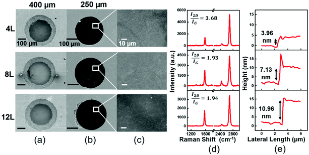
Suspended graphene sheets with a controllable thickness and large area are first prepared on a holey silicon substrate via a water transfer method, as illustrated in Fig. S3.† Due to the large inkjet drop size (∼40–60 μm), LSG layers with diameters up to 400 μm (Fig. 1) are prepared in this study to infer their mechanical strength from drop impact dynamics. The preparation is briefly described here. First, fully covered single layer graphene grown on a Cu substrate through chemical vapor deposition (CVD) is transferred from the Cu substrate through the conventional PMMA assisted process. By repeating the transfer process, multiple-layer graphene films are prepared and transferred on the surface of a water tank. The floated film was then scooped onto the holey silicon substrate to result in a LSG sample with a controlled number of layers. For more details, please see the ESI.†The scanning electron microscopy (SEM) images show the graphene sheets suspended well over holes (400 μm or 250 μm diameter) regardless of the number of layers (Fig. 1a and b). However, a closer look shows that the surface of the suspended graphene sheets is quite crumpled (Fig. 1c). Moreover, the crumples increase with the number of layers possibly due to more wrinkle generation in the drying process after being transferred from water surfaces. To further identify the molecular structure of the LSG, Raman spectroscopy is used (Fig. 1d). For the 4-layer suspended graphene, the Raman spectrum shows a high I2D/IG peak ratio (>3), indicating a high electron mobility in the LSG due to no electron scattering from the substrate. Moreover, no D peak is observed, indicating no defect in the stacked graphene layers. I2D/IG for the 8 and 12-layer samples dropped to ∼2, and a slight D band was found. Nevertheless, the 2D band is still symmetric and narrow, indicating that there is no phonon coupling between the layers (the inter-layer distance is large). Atomic force microscopy (AFM) images are acquired at the film edge to obtain the film thickness. The thickness of 4-, 8-, and 12-layer graphene is 3.96 nm, 7.13 nm, 10.96 nm, respectively (Fig. 1e). The measured thickness is higher than the ideal flat stacking of graphene probably due to the additional interlayer space created by the crumples on each graphene sheet.
Drop impingement dynamics on LSG
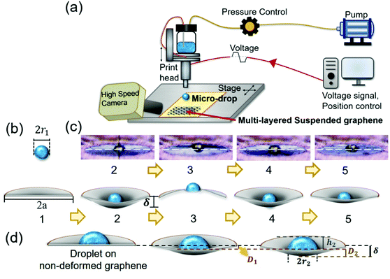
The dynamical response of suspended graphene during drop impinging is used to probe the mechanical strength of the LSG. A printing platform (MicroFab, JetLab 4) with an electrically controlled stage (Fig. S4†) is used to precisely deposit droplets on the prepared LSG. A piezoelectric ink jet nozzle of 50 μm diameter is actuated electrically to eject liquid droplets with D = 65 μm with a stable speed of U0 = 5.9 m s−1. To avoid evaporation problems or droplet shrinkage in the impinging process, a polymeric fluid, poly(ethylene glycol) (PEG-200, Sigma-Aldrich), is used for drop ejection due to its high boiling point. The drop impinging dynamics on LSG is observed using a high-speed camera (SN23990 E310L, PHANTOM, AMETEK's) with a frame rate of 10![[thin space (1/6-em)]](https://www.rsc.org/images/entities/char_2009.gif) 000 1 s−1. More details can be found in the ESI.†
000 1 s−1. More details can be found in the ESI.†
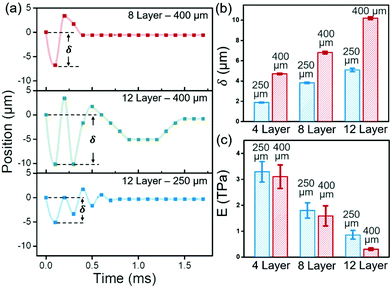
The momentum transfer upon drop impact results in significant LSG deformation. Right after drop impact, LSG takes up the kinetic energy of the drop and deforms. Then, the reflected pressure from the rear side of LSG causes an upward deflection. Meanwhile, some energy in the LSG is transformed to the droplet, resulting in a decreasing amplitude of oscillation. The dynamical position of the LSG deflection can be measured from the midline between the droplet and the reflected drop image (Fig. 2). Some typical results are shown in Fig. 3. For 8-layer LSG with a diameter of 400 μm, the LSG undergoes a maximum deflection of 7 μm after drop impingement, and the kinetic energy provided by the drop is totally damped out with one oscillating cycle in a period of 0.4 ms. Interestingly, for 12-layer LSG with the same diameter, 3 oscillating cycles are observed with a longer time period of 1.6 ms, and the maximum deflection reached 10 μm. The larger deflection and more oscillation cycles indicate that 12-layer LSG is easier to be deformed than 8-layer ones by the same reflected pressure. Thus, a lower effective Young's modulus is expected for thicker LSG, which is consistent with both simulation17 and experiments14,15,28–30 in the literature. On the other hand, for 12-layer LSG with 250 μm diameter, a maximum deflection of 5 μm is observed and the oscillation stops within 1 ms. Thus, the LSG with 250 μm diameter is expected to be stiffer than the 400 μm ones, i.e. a larger effective Young's modulus with a smaller suspended area, which is in good agreement with the results of other experiments.15
To quantitatively evaluate the stiffness, the effective Young's moduli of LSGs with different thicknesses and diameters are calculated from the maximum deflection and drop velocity. The impact force exerted by the droplet can be estimated from fluid mechanics and varies with the Reynolds number, Re = U0D/ν. With an impact velocity U0 = 5.91 m s−1 and viscosity ν = 4.3 cSt, the Reynolds number of the PEG drop of diameter D = 65 μm is 89.34. For 0.7 < Re < 200, viscous forces should be taken into consideration in the drop impact, and the force exerted on the LSG can be obtained from the force balance with the momentum transformation of the deformed drop as31
 | (1) |
 | (2) |
Static LSG deflection
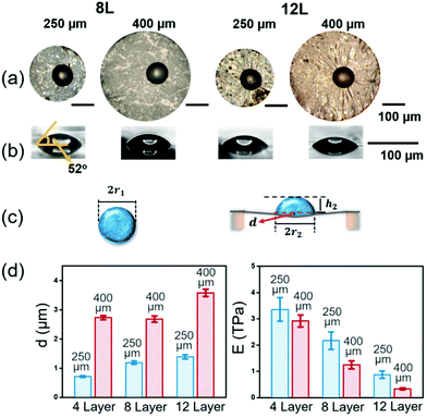
The mechanical strength of the LSG can also be evaluated from the static deflection caused by capillary forces. After the oscillation vanished, the drop is sessile on LSG, and slight deformation can be observed from the side view images. The static deflection in the central area of the wetted LSG can be calculated from the sessile drop shape. Assuming nearly no evaporation during the impact process, the drop volume can be evaluated using the drop radius r1 before the impact (∼32 μm) as follows: | (3) |
After equilibrating on the LSG, the sessile drop volume on the deflected LSG can be calculated as the sum of a spherical cap above and a cone below the contact points of the drop shape33,34 (Fig. 4c),
 | (4) |
To obtain quantitative results for effective Young's modulus, the relationship between the static deflection caused capillary pressure is used here. For a liquid droplet on a thin film, the wetted area suffers a uniform Laplace pressure
 | (5) |
 | (6) |
| Method | 4 layer 250 μm | 4 layer 400 μm | 8 layer 250 μm | 8 layer 400 μm | 12 layer 250 μm | 12 layer 400 μm |
|---|---|---|---|---|---|---|
| Impact deflection | 3.29 TPa | 3.1 TPa | 1.8 TPa | 1.59 TPa | 855 GPa | 306 GPa |
| Sessile droplet deformation | 3.36 TPa | 2.92 TPa | 2.17 TPa | 1.25 TPa | 874 GPa | 337 GPa |
| Number of wrinkles | N/A | N/A | N/A | N/A | 889 GPa | 333 GPa |
Besides the static LSG sheet deflection, the microscopy images (Fig. 5a) also indicate that the capillary force of the sessile drops induces wrinkles on LSG. However, wrinkles only appear on the surface of 12-layer LSG, indicating larger deformation upon impact since they are softer than any other LSG sheets. For a flexible thin film under load, the compressive stress inside the loading region is larger than that outside,37,38 and induces buckling wrinkles aligning perpendicular to the compression direction.39 The configuration of wrinkles can be described using the Föppl–von Kármán (FvK) equations,40 and the number of wrinkles N induced by capillary force can be expressed as14,20
 | (7) |
The number of wrinkles of 12-layer suspended graphene of diameter 250 μm and 400 μm is 18 and 23, respectively. The effective Young's modulus calculated from eqn (7) is 889 GPa and 333 GPa, comparable to the effective Young's modulus calculated from the impinging deformation and sessile droplet on thin films (Table 1). Thus, all the results are in good agreement and indicate that LSG becomes stiffer as the thickness or width decreases.
Internal stress of LSG after drop impact
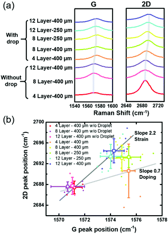
The internal nano-structures in LSG can be disturbed by the large strain upon drop impact and can be probed by Raman spectroscopy. The absence of bandgaps in graphene allows all wavelengths of incident radiation resonant, and thus Raman spectroscopy is an excellent diagnostic method to characterize the structural and electronic properties in graphene.41For LSG before drop deposition, as shown in Fig. 5a, the peak positions are nearly the same regardless of the number of layers, indicating no significant structural variation in these samples. However, after drop deposition, the droplet-induced strains in LSG result in broadened peaks at G and 2D modes. Moreover, the blue shift in the 2D band is more obvious with the increasing number of layers.
To identify the mechanisms of the broadening and shifting peaks, the peak positions of G and 2D modes in Raman spectroscopy are plotted against each other in Fig. 5b. According to the literature, graphene in strain causes the shift of the Dirac cone and thus alters the 2D mode energy,42 while doping in graphene moves the G mode to a higher wavenumber. Previous studies42–45 show that doping-induced Raman shifts in the 2D band are only slightly lower than those in the G band, and thus scatter along a line with a slope of 0.7. As shown in Fig. 5b, the peak positions of 4-layer LSG follow this trend, indicating that the PEG drop on 4-layer LSG induces mostly hole doping in graphene rather than strain. This result also coincides with the little deflection of 4-layer LSG in the drop impinging or sessile drop tests. On the other hand, the strain-induced Raman shift is much larger in the 2D band than in the G band and scatters along a line with a slope of 2.2. The peak positions of 8- or 12-layer LSG follow this line and therefore can infer more significant drop-induced strain effects than doping. Thus, the droplet on suspended graphene inducing compressive strain resulted from the film deflection. This drop-induced strain for large or thick LSG is consistent with other simulation and experimental results,46,47 and also implies that the effective Young's modulus of LSG decreases as the thickness increases, despite that the peak positions in the Raman spectra are not very much different from that of the bulk graphite. Furthermore, the inevitable crumples on suspended graphene during the fabrication process will decrease the in-plane stiffness compared to the intrinsic graphene.48
Conclusions
A novel drop impact method is developed here to probe the mechanical strength of large area suspended graphene (LSG). Large area suspended graphene (LSG) layers with a diameter up to 400 μm and a nanometer thickness are prepared through transferring chemical vapor deposition grown graphene from copper substrates. Using an ink-jet printing system, the drops of micrometer size can impinge directly and precisely at the center of LSG. The dynamics of the drop impinging process is recorded by high-speed photography to evaluate the deflection of LSG caused by drop impact. Comparable effective Young's modulus values ranging from 0.3 to 3.4 TPa are calculated by three methods: dynamical LSG deformation, static sessile drop induced deformation, and the number of wrinkles on LSG. Furthermore, the deformation induced strain can also be quantified by the shift in peaks in the Raman spectrum. All results indicate that the effective Young's modulus of suspended graphene sheets increases with decreasing thickness and suspended area. These comprehensive results from complementary methodologies with precise LSG thickness control down to the nanometer scale provide good evidence to resolve the debate on the thickness dependence of mechanical strength for LSG.Conflicts of interest
The authors declare no conflicts of interest.Acknowledgements
This study is supported by the Ministry of Science and Technology in Taiwan (MOST-109-2628-M-008-004-MY3, MOST 109-2221-E-002-064-MY3) and the National Taiwan University (110L891503).References
- K. I. Bolotin, K. J. Sikes, Z. Jiang, M. Klima, G. Fudenberg, J. Hone, P. Kim and H. L. Stormer, Solid State Commun., 2008, 146, 351–355 CrossRef CAS.
- A. A. Balandin, S. Ghosh, W. Bao, I. Calizo, D. Teweldebrhan, F. Miao and C. N. Lau, Nano Lett., 2008, 8, 902–907 CrossRef CAS.
- C. Lee, X. Wei, J. W. Kysar and J. Hone, Science, 2008, 321, 385–388 CrossRef CAS.
- F. Schedin, A. K. Geim, S. V. Morozov, E. W. Hill, P. Blake, M. I. Katsnelson and K. S. Novoselov, Nat. Mater., 2007, 6, 652–655 CrossRef CAS PubMed.
- Y. M. Chen, S. M. He, C. H. Huang, C. C. Huang, W. P. Shih, C. L. Chu, J. Kong, J. Li and C. Y. Su, Nanoscale, 2016, 8, 3555 RSC.
- A. D. Smith, F. Niklaus, A. Paussa, S. Vaziri, A. C. Fischer, M. Sterner, F. Forsberg, A. Delin, D. Esseni, P. Palestri, M. Östling and M. C. Lemme, Nano Lett., 2013, 13, 3237–3242 CrossRef CAS PubMed.
- P. Li, B. Zhang and T. Cui, Biosens. Bioelectron., 2015, 72, 168–174 CrossRef CAS PubMed.
- B. M. Venkatesan and R. Bashir, Nat. Nanotechnol., 2011, 6, 615–624 CrossRef CAS PubMed.
- J. S. Bunch, A. M. Van DerZande, S. S. Verbridge, I. W. Frank, D. M. Tanenbaum, J. M. Parpia, H. G. Craighead and P. L. McEuen, Science, 2007, 315, 490–493 CrossRef CAS.
- J. N. Longchamp, T. Latychevskaia, C. Escher and H. W. Fink, Appl. Phys. Lett., 2015, 107, 133101 CrossRef.
- M. Freitag, T. Low and P. Avouris, Nano Lett., 2013, 13, 1644–1648 CrossRef CAS.
- J. S. Bunch, S. S. Verbridge, J. S. Alden, A. M. van derZande, J. M. Parpia, H. G. Craighead and P. L. Mceuen, Nano Lett., 2008, 8, 2458–2462 CrossRef CAS PubMed.
- K. Celebi, J. Buchheim, R. M. Wyss, A. Droudian, P. Gasser, I. Shorubalko, J. IlKye, C. Lee and H. G. Park, Science, 2014, 344, 289–292 CrossRef CAS.
- J. Chang, K. B. Toga, J. D. Paulsen, N. Menon and T. P. Russell, Macromolecules, 2018, 51, 6764–6770 CrossRef CAS.
- H. K. Nguyen, S. Fujinami and K. Nakajima, Polymer, 2016, 105, 64–71 CrossRef CAS.
- A. K. Katiyar, A. A. Davidson, H. Jang, Y. Hwangbo, B. Han, S. Lee, Y. Hagiwara, T. Shimada, H. Hirakata, T. Kitamura and J. H. Ahn, Nanoscale, 2019, 11, 15184–15194 RSC.
- T. Zhong, J. Li and K. Zhang, J. Appl. Phys., 2019, 125, 175110 CrossRef.
- Y. Huang, J. Wu and K. C. Hwang, Phys. Rev. B: Condens. Matter Mater. Phys., 2006, 74, 245413 CrossRef.
- Y. W. Sun, D. G. Papageorgiou, C. J. Humphreys, D. J. Dunstan, P. Puech, J. E. Proctor, C. Bousige, D. Machon and A. San-Miguel, Appl. Phys. Rev., 2021, 8, 021310 CAS.
- J. Huang, M. Juszkiewicz, W. H. de Jeu, E. Cerda, T. Emrick and N. Menon, Science, 2007, 317, 650–653 CrossRef CAS PubMed.
- J. H. Lee, P. E. Loya, J. Lou and E. L. Thomas, Science, 2014, 346, 1092–1096 CrossRef CAS PubMed.
- B. Keshavarz, S. I. Green and D. T. Eadie, AIChE J., 2012, 58, 3568–3577 CrossRef CAS.
- M. Pegg, R. Purvis and A. Korobkin, J. Fluid Mech., 2018, 839, 561–593 CrossRef CAS.
- R. E. Pepper, L. Courbin and H. A. Stone, Phys. Fluids, 2008, 20, 082103 CrossRef.
- P. Aillaud, F. Duchaine, L. Y. M. Gicquel and S. Didorally, Phys. Fluids, 2016, 28, 095110 CrossRef.
- A. L. Yarin, Annu. Rev. Fluid Mech., 2006, 38, 159–192 CrossRef.
- T. Koishi, K. Yasuoka and X. C. Zeng, Langmuir, 2017, 33, 10184–10192 CrossRef CAS.
- B. Ashrafi, K. Das, R. LeFaive, P. Hubert and S. Vengallatore, Exp. Mech., 2012, 52, 371–378 CrossRef CAS.
- C. W. Lim and L. H. He, Int. J. Mech. Sci., 2004, 46, 1715–1726 CrossRef.
- M. A. Haque and M. T. A. Saif, Proc. Natl. Acad. Sci. U. S. A., 2004, 101, 6335–6340 CrossRef CAS.
- L. Gordillo, T. P. Sun and X. Cheng, J. Fluid Mech., 2018, 840, 190–214 CrossRef CAS.
- M. T. Zafarani-Moattar and N. Tohidifar, J. Chem. Eng. Data, 2006, 51, 1769–1774 CrossRef CAS.
- N. Nadermann, C. Y. Hui and A. Jagota, Proc. Natl. Acad. Sci. U. S. A., 2013, 110, 10541–10545 CrossRef CAS.
- R. D. Schulman, R. Ledesma-Alonso, T. Salez, E. Raphaël and K. Dalnoki-Veress, Phys. Rev. Lett., 2017, 118, 198002 CrossRef PubMed.
- W. C. Young and R. G. Budynas, Roark's Formulas for Stress and Strain, McGraw-Hill, New York, 7th edn, 2002 Search PubMed.
- S. Timoshenko and S. Woinowsky-Krieger, Theory of Plates and Shells, McGraw-Hill, New York, 2nd edn, 1959 Search PubMed.
- B. Davidovitch, R. D. Schroll, D. Vella, M. Adda-Bedia and E. A. Cerda, Proc. Natl. Acad. Sci. U. S. A., 2011, 108, 18227–18232 CrossRef CAS.
- J. C. Géminard, R. Bernal and F. Melo, Eur. Phys. J. E, 2004, 15, 117–126 CrossRef.
- R. Bernal, C. Tassius, F. Melo and J. C. Géminard, Eur. Phys. J. E, 2011, 34, 13 CrossRef CAS PubMed.
- E. Cerda and L. Mahadevan, Phys. Rev. Lett., 2003, 90, 074302 CrossRef CAS.
- A. C. Ferrari and D. M. Basko, Nat. Nanotechnol., 2013, 8, 235–246 CrossRef CAS.
- M. Huang, H. Yan, T. F. Heinz and J. Hone, Nano Lett., 2010, 10, 4074–4079 CrossRef CAS.
- J. E. Lee, G. Ahn, J. Shim, Y. S. Lee and S. Ryu, Nat. Commun., 2012, 3, 1024 CrossRef.
- J. Yan, Y. Zhang, P. Kim and A. Pinczuk, Phys. Rev. Lett., 2007, 98, 166802 CrossRef.
- C. Neumann, S. Reichardt, P. Venezuela, M. Drögeler, L. Banszerus, M. Schmitz, K. Watanabe, T. Taniguchi, F. Mauri, B. Beschoten, S. VRotkin and C. Stampfer, Nat. Commun., 2015, 6, 8429 CrossRef CAS.
- S. Neukirch, A. Antkowiak and J. J. Marigo, Phys. Rev. E: Stat., Nonlinear, Soft Matter Phys., 2014, 89, 012401 CrossRef CAS PubMed.
- A. Marchand, S. Das, J. H. Snoeijer and B. Andreotti, Phys. Rev. Lett., 2012, 108, 094301 CrossRef.
- R. J. T. Nicholl, H. J. Conley, N. V. Lavrik, I. Vlassiouk, Y. S. Puzyrev, V. P. Sreenivas, S. T. Pantelides and K. I. Bolotin, Nat. Commun., 2015, 6, 8789 CrossRef CAS.
Footnote |
| † Electronic supplementary information (ESI) available. See DOI: 10.1039/d1nr05918a |
| This journal is © The Royal Society of Chemistry 2022 |

