 Open Access Article
Enhanced extraordinary terahertz transmission through coupling between silicon resonators†
Jinmei
Song
a,
Yanpeng
Shi
 *a,
Meiping
Li
a,
Xiaoyu
Liu
a,
Xiaodong
Wang
 b,
Fuhua
Yang
b and
Huayu
Feng
a
aSchool of Microelectronics, Shandong University, Jinan 250100, China. E-mail: ypshi@sdu.edu.cn
bEngineering Research Center for Semiconductor Integrated Technology, Institute of Semiconductors, Chinese Academy of Sciences, Beijing 100083, China
First published on 2nd May 2022
Abstract
By using Mie resonance coupling effects, low-loss silicon particles as receiving or transmitting antennas can strongly localize the electromagnetic field. Enhanced extraordinary optical transmission (EEOT) is generated by placing two such silicon particles symmetrically on both sides of subwavelength hole arrays in the terahertz (THz) region. When the hole radius r is 17 times smaller than the resonance wavelength λ (r/λ = 0.06), the enhancement factors of the resonator–hole and the resonator–resonator coupling structures are 154- and 629-fold compared to that of the hole-only structure, respectively. The current distribution, magnetic field and Poynting vector are numerically simulated to reveal the mechanism of the proposed structure. Moreover, the Mie resonance coupling and the induced THz EEOT can be tuned in a wide frequency range. Our results provide a reference for the miniaturization of THz systems.
Introduction
The interest in enhanced transmission of electromagnetic waves through subwavelength holes has been increasing significantly for a long time.1–6 According to Bethe's theory, the transmission efficiency through a small hole scales with the ratio of r/λ.4 If the hole radius r is much smaller than the incident light wavelength λ, the transmission efficiency is close to zero.7 How to enhance the transmission efficiency of subwavelength holes was always a tough problem in the process of modulating optical transmission until Ebbesen et al. discovered the extraordinary optical transmission (EOT) phenomenon in a two-dimensional metal hole array.8 The transmittance at a specific wavelength is much higher than that predicted by Bethe's theory. The EOT phenomenon provides a brand-new method to control the movement of photons and improves the transmission of optical information.9,10 It attracted extensive research interest in the fields of optical communication, spectral imaging, sensors, tunable optical filters, absorbers, and near-field optics.4,11–16 A large number of theoretical and experimental studies have verified that EOT can be produced through metal holes or periodic slits.17–19 In 2004, Tanaka and others simulated an I-shaped aperture in a thick metallic screen and obtained a high near-field intensity. Such a characteristic is also attributed to the generation and propagation of surface plasmon polaritons (SPPs) in metal hole arrays.20 It is a common understanding that in many optical systems, such as sensors and nanolithography, if a small hole is partially or completely covered by an opaque metal, it will hinder the propagation of light.21–23 In recent years, some scholars have found that by designing specific functional units in or on holes, the hole array can instead produce greatly enhanced transmission, which is mainly due to the antenna effect of the particles.6,24 Sugaya's research group in 2017 reported a technique for tuning a resonant frequency and enhancing the transmission of a bull's eye plasmonic antenna by forming dielectric materials on a subwavelength aperture.25 They observed that the use of the dielectric material shifted the peak frequency of THz transmission through the aperture, and also increased the transmission by 20%.In fact, when the particles are placed in a metal hole, the localized surface plasmon resonances (LSPRs) can be effectively coupled with the SPPs, further enhancing the extraordinary optical transmission.26,27 In 2020, Wang's research group showed that a nanorod inside a nanohole acts as a nano-antenna and the length of the nanorod determines the resonance radiation wavelength.28 They demonstrated that the proposed structure has a new EOT mode when the polarization of incident light is along the long axis of the nanorod. This new mode possesses high local E-fields and the transmission intensity can reach 68% for a wavelength of 1.31 μm. Our recent study shows that a THz enhanced extraordinary optical transmission (EEOT) is generated when a gold hole array is combined with a gold hemisphere particle in the middle.29 This THz EEOT mode, caused by the coupling between the SPPs and LSPRs, improves the transmission intensity to 97%, and the bandwidth is nine times wider than that in the case of no particle in the hole. Different from the devices based on excitation SPPs and LSPRs to realize EEOT, another method of realizing EEOT is to place a particle antenna on a hole, which can take advantage of particle resonance to concentrate and re-radiate light energy.30 In 2009, Cakmak et al. reported an EEOT through a single circular subwavelength aperture that is incorporated with a split ring resonator at the microwave regime. Transmission enhancement factors as high as 530 were observed in the experiments when the SRR was located in front of the aperture in order to efficiently couple the electromagnetic field.31 However, due to the non-radiative ohmic loss in metal resonators, light energy suffers serious loss during light transmission, which further limits the application of such structures.32,33 Besides, EOT structures integrated with dielectric resonators were also proposed. By using the Mie resonance coupling between two low-loss ceramic antennas, Guo’s group demonstrated that the broadband transmission is 300 times higher than the transmission of an aperture-only structure in the microwave band.34 In the relatively underdeveloped but technologically important terahertz regime, it is of great significance to use Mie resonance of dielectric particles to further enhance the transmission through subwavelength holes.
In this work, we propose a gold subwavelength hole structure with two low-loss silicon particles symmetrically placed on both sides of the hole. In the 1st Mie resonance mode, the silicon particles can be regarded as magnetic dipole antennas, which can effectively guide the incoming electromagnetic waves to the subwavelength aperture, and then transmit them to the free-space through Mie resonance coupling. The basic idea of this THz EEOT phenomenon can be understood as the process of first coupling the electromagnetic energy through the left silicon antenna, resonating with the SPPs excited at the metal hole array, and then re-radiating the energy through the right silicon antenna. Even though the size of the hole is much smaller than the incident wavelength (r/λ = 0.06), a 629-fold enhancement is obtained by using the magnetic coupling of the two silicon particles (resonator–resonator coupling) in the proximity of the aperture. The structure preferably enhances transmission compared to the structures with only one particle on the left side of the hole (resonator–hole coupling), or with one particle on the right side (hole–resonator coupling), or with no particle (hole-only). Furthermore, we discuss the physical mechanism of EEOT by simulating transmission, reflection, magnetic field, and current distribution. This mechanism could also be referred to other light bands, such as microwaves, infrared, etc. The proposed structure realizes EEOT by using Mie resonance of low-loss silicon particles, which not only solves the problem of metal ohmic loss when using metal resonators, but also further reduces the device size in the THz band. Meanwhile, it shows excellent advantages such as high transmission efficiency, strong localization of the electromagnetic field, and considerable compatibility with existing semiconductor processes.
Results and discussion
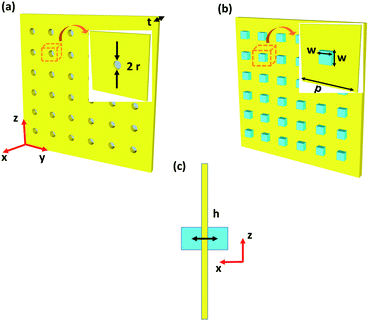
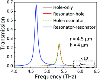
The diagram of a subwavelength hole with radius r in a gold film is shown in the inset of Fig. 1(a). The Au film thickness is 1 μm, which is much larger than the skin depth and opaque to the incident plane wave.32 The optical constants of Au are quoted from the Drude model.35 For the Mie resonance coupled THz transmission, two silicon particles with a side length w of 12 μm are symmetrically placed on both sides of the small hole, as shown in Fig. 1(b). The low loss silicon permittivity is described by the Palik model. The square period p of the unit is fixed at 50 μm. Fig. 1(c) shows the cross-section of one-unit cell in the xz plane. The height of two identical particles h is equal to 4 μm. Three-dimensional finite-difference time-domain (FDTD) solutions are performed to calculate the transmission spectra and electromagnetic field distribution. Perfectly matched layer boundary condition is used on the x direction and periodic boundary conditions are placed on the y and z directions. A spatial step discretization of 0.8 × 0.8 × 0.1 μm3, a running time of 800 ps and an auto-shutoff minimum of 1 × 10⁻⁶ in the simulations are adopted to trade between accuracy, RAM capacity, and running time. A plane wave source propagates along the x direction with an electric field polarized along the y direction.As shown in Fig. 2, the transmission spectra of hole-only, resonator–hole coupling, hole–resonator coupling and resonator–resonator coupling arrays are numerically simulated when the r and h are fixed at 4.5 and 4 μm, respectively. For the hole-only structure, it is obvious that the maximum transmission at 5.98 THz is about 0.002 (as shown by the black line in Fig. 2, amplified 10 times). The same result was also obtained from HFSS simulation. It can be seen that there is no obvious sharp resonance in the transmission spectrum of the hole-only structure. The weak transmission peak is due to the much smaller ohmic loss and hole radius than the period and incident wavelength, so electromagnetic waves cannot be effectively transmitted. When a single silicon particle is placed on the left side of the hole (namely, the resonator–hole coupling structure, red line in Fig. 2), the peak red-shifts to 5.36 THz and the transmission intensity increases significantly to 0.24, implying an enhancement factor of 120. Interestingly, with the same hole parameters, the transmission spectrum of the resonator–hole coupling structure (red line in Fig. 2) is almost the same as that of the hole–resonator coupling structure (green dotted line in Fig. 2). However, as will be discussed below, the detailed coupling process, current distribution and reflection intensity are quite different between these two structures. When two silicon particles are placed symmetrically on both sides of a subwavelength hole, the transmission intensity is as large as 0.68 in the 4.66 THz region (blue line in Fig. 2), and the enhancement factor can reach up to 336, revealing a greatly enhanced THz EOT effect.
When the plane wave is incident to a single isolated dielectric object, the scattered field can be decomposed into a multiple series. Based on the exact Mie solution of the diffraction problem, the scattered electric field and magnetic field by a small spherical particle are proportional to the scattering coefficients am and bm, respectively,36
 | (1) |
 | (2) |
It is well known that two resonating particles with the same resonance frequency tend to effectively couple and converge field energy, where the transfer is mediated by the overlap of the near magnetic fields of the two dielectric resonators. The two resonantly coupled particles can be expressed by the coupled-mode theory. The physical system is described using the following equations,38
| ȧ1(t) = (iω1 − Γ1)a1(t) + iκ12a2(t) + F1(t) | (3) |
| ȧ2(t) = (iω2 − Γ2)a2(t) + iκ21a1(t) + F2(t) | (4) |
 | (5) |
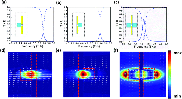
This process can be further understood with the aid of the corresponding reflection spectra. Fig. 4(a)–(c) show the transmission and reflection curves of the resonator–hole coupling, hole–resonator coupling and resonator–resonator coupling structures when r is 4.5 μm. The magnetic field and Poynting vector distribution of the three corresponding structures are shown in Fig. 4(d)–(f). As shown in Fig. 4(a) and (b), when one silicon particle is placed at the left or right side of a small hole, the transmission spectra are similar but the reflection curves are obviously different. If there is one resonator on the left side, the reflection is relatively low, about 0.31 at 5.36 THz (blue dashed line in Fig. 4(a)), and the transmission intensity is 0.24 (blue line in Fig. 4(a)). The xz-plane distribution of the magnetic field and Poynting vector at the transmission peak of the resonator–hole structure are depicted in Fig. 4(d). As discussed above, the particle acts as a receiving antenna to efficiently capture the incident energy, generating a strong magnetic field in the center of the silicon particle. Due to the lack of a magnetic dipole resonator on the other side, the asymmetric structure cannot couple all the localized electromagnetic fields, so the energy transmitted through the subwavelength aperture is relatively weak. A part of the energy that is localized in the particle is absorbed, reflected or lost during the propagation between the particle and the hole. When placing the resonator on the right side of the subwavelength hole, as shown in Fig. 4(b), the reflection intensity is up to 0.72. The rest of the electromagnetic wave will also be effectively captured by the magnetic dipole resonator on the right side through the subwavelength aperture, thereby enhancing the energy radiation into free-space, which could be clearly observed in Fig. 4(e). Obviously, a part of the field energy flows into the hole from the left area, and then the right silicon particle acts as a transmitting antenna to greatly trap the energy passing through the small hole into the magnetic dipole resonator.
The reflection and transmission of the resonator–resonator coupling structure are shown in Fig. 4(c). The reflection intensity is very low at the peak position of 4.66 THz, about 0.03. Almost all energy is coupled to the small hole through the forward magnetic dipole resonator. The transmission peak amplitude is as high as 0.68, which means that the magnetic dipole resonator effectively couples the electromagnetic wave through the subwavelength hole and then enhances the transmission. Only a small part of the energy is absorbed during the transmission process. Fig. 4(f) shows the magnetic field and Poynting vector distribution at 4.66 THz of the resonator–resonator coupling structure. Since the silicon particles are symmetrically placed on both sides of the small aperture, the particles act as receiving and transmitting antennas that can uninterruptedly couple and transmit incident energy. The magnetic field in Fig. 4(f) is symmetrically distributed on both sides of the subwavelength metal hole. Now, two magnetic resonators with the same geometric size have the same resonance frequency, and the composed system is in a critical coupling state at this frequency, so the energy transmission efficiency reaches the maximum. Hence, THz EEOT based on the Mie resonance coupling of silicon particles is successfully realized in subwavelength metal holes.
Fig. 5 illustrates the transmission map of the resonator–hole structure when h varies from 3.5 to 6.5 μm. The transmission peak frequency can be shifted from 5.8 THz to around 4.95 THz and it shows that in such a small hole structure, transmission enhancement in different frequency bands can be achieved by tuning the size of the dielectric particles. When the height of the particle increases, it can be equivalently described as increasing capacitance. This enhanced capacitance can store energy in the form of electromagnetic fields. The process described above leads to an effective increase in the net capacitance of the structure, which shifts the resonance peak progressively to the lower side of the frequency spectrum.37,40,41 It is clearly shown that the Mie resonance structure can be dynamically and continuously modulated using the parameters of dielectric particles.
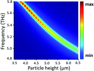 | ||
| Fig. 5 Transmission map of the resonator–hole coupling structure with different silicon particle heights h. | ||
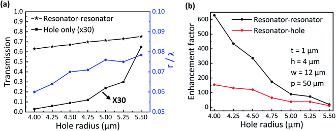
Furthermore, the transmission peak intensity of the resonator–resonator coupling and the hole-only structures (the left axis) and the r/λ of the resonator–resonator coupling (the right axis) with different hole radii are shown in Fig. 6(a). As the hole radius r changes from 4.0 to 5.5 μm, the peak intensity of the resonator–resonator coupling structure (black star line) increases from 0.63 to 0.76, and the variation range of r/λ fluctuates between 0.06 and 0.08 (blue line), indicating that this structure can achieve THz EEOT in a wide range of subwavelength hole radii. Importantly, enhanced THz transmission based on the plasmon coupling effects of surface plasmon polaritons and localized surface plasmon resonance is difficult to realize in tiny holes (see ref. 29). Meanwhile, to better verify and reveal the advantages of the proposed resonator–resonator coupling structure, the comparison of its transmission enhancement factor with that of the resonator–hole coupling structure is presented in Fig. 6(b). It can be clearly seen that at a subwavelength hole radius of 4 μm, the two-particle structure can achieve 629-fold enhancement compared to the hole-only structure, and the resonator–hole coupling structure shows 154-fold enhancement. When the hole radius increases from 4.0 to 5.5 μm, the enhancement effect gradually weakens, but it still remains higher than 19. The transmission enhancement factor is the ratio of the transmission of the resonator–resonator coupling structure to that of the hole-only structure. The transmission intensity (black square line, amplified 30 times) of the hole-only structure as a function of hole radius is shown in Fig. 6(a). With the hole radius r changing from 4.0 to 5.5 μm, the transmission intensity of the hole-only structure is significantly increased. Although the transmission intensity of the resonator–resonator coupling structure increases, the magnitude of the increase is smaller than that of the hole-only structure transmission, so the transmission enhancement factor is decreasing. More importantly, the use of resonator–resonator coupling to enhance subwavelength hole transmission leads to more than twice the enhancement factor of only one resonator coupling structure. Therefore, the Mie resonance coupling of two silicon particles is more suitable for subwavelength hole EEOT in the THz region.
Conclusions
By placing two low-loss silicon particles symmetrically on either side of subwavelength holes, greatly enhanced THz EOT has been obtained. The Mie resonance coupling between a pair of magnetic dipole resonators can effectively localize electromagnetic fields. The internal current between the silicon particles and the subwavelength holes depicts the excitation of the circulating current throughout the structure, which ultimately suggests that the magnetic dipole resonance generated in the silicon particles and the excited SPPs near the hole array together contribute to the EEOT. Compared with the hole-only structure, the resonator–hole and resonator–resonator coupling achieved 154- and 629-fold transmission enhancements, respectively. When the hole radius varies from 4.0 to 5.5 μm, which is much smaller than the resonance wavelength, the transmission increases and the enhancement factor decreases accordingly. We numerically simulated the reflection, magnetic field and current distribution of the proposed structure in detail. Also, the THz EEOT can be achieved in different frequency bands by changing the size of particles. Different from the traditional structure of EEOT realized by metal surface plasmon resonance, the proposed structure reduces ohmic loss and realizes high transmission efficiency and strong magnetic field coupling. All in all, these results extend our basic understanding of the EOT phenomenon and provide a reference for many potential THz optoelectronic devices.Conflicts of interest
There are no conflicts to declare.Acknowledgements
This work was sponsored by the National Natural Science Foundation of China (No. 61805127, 11804191), the Natural Science Foundation of Shandong Province, China (No. ZR2019BF014, ZR2018BA033), the China Postdoctoral Science Foundation funded project (No. 2015M582073), the Postdoctoral Innovation Program of Shandong Province (No. 201602017) and the Fundamental Research Funds of Shandong University (No. 2018TB002, 2020HW016).Notes and references
- L. Martin-Moreno, F. J. Garcia-Vidal, H. J. Lezec, K. M. Pellerin, T. Thio, J. B. Pendry and T. W. Ebbesen, Phys. Rev. Lett., 2001, 86, 1114–1117 CrossRef CAS.
- F. J. García de Abajo, Rev. Mod. Phys., 2007, 79, 1267–1290 CrossRef.
- C. Genet and T. W. Ebbesen, Nature, 2007, 445, 39–46 CrossRef CAS.
- H. Liu and P. Lalanne, Nature, 2008, 452, 728–731 CrossRef CAS.
- F. J. Garcia-Vidal, L. Martin-Moreno, T. W. Ebbesen and L. Kuipers, Rev. Mod. Phys., 2010, 82, 729–787 CrossRef.
- V. Giannini, A. Berrier, S. A. Maier, J. Sánchez-Gil and J. G. Rivas, Opt. Express, 2010, 18, 2797–2807 CrossRef CAS PubMed.
- H. A. Bethe, Phys. Rev., 1944, 66, 163–182 CrossRef.
- T. W. Ebbesen, H. J. Lezec, H. F. Ghaemi, T. Thio and P. A. Wolff, Nature, 1998, 391, 1114–1117 CrossRef.
- J. Bravo-Abad, A. Degiron, F. Przybilla, C. Genet, F. J. García-Vidal, L. Martín-Moreno and T. W. Ebbesen, Nat. Phys., 2006, 2, 120–123 Search PubMed.
- H. Liu and P. Lalanne, Nature, 2008, 452, 728–731 CrossRef CAS PubMed.
- M. R. Gonçalves, H. Minassian and A. Melikyan, J. Phys. D: Appl. Phys., 2020, 53, 44 CrossRef.
- K. Wen, X.-Q. Luo, Z. Chen, W. Zhu, W. Guo and X. Wang, Plasmonics, 2019, 14, 1649–1657 CrossRef.
- I. Jáuregui-López, P. Rodriguez-Ulibarri, S. Kuznetsov and N. A. Nikolaev, Sensors, 2018, 18, 3848 CrossRef.
- M. B. Ross and G. C. Schatz, J. Phys. D: Appl. Phys., 2015, 48, 184004 CrossRef.
- T. Sondergaard, S. I. Bozhevolnyi, S. M. Novikov, J. Beermann, E. Devaux and T. W. Ebbesen, Nano Lett., 2010, 10, 3123–3128 CrossRef CAS PubMed.
- T. G. Mayerhöfer, R. Knipper, U. Hübner, D. Cialla-May, K. Weber, H.-G. Meyer and J. Popp, ACS Photonics, 2015, 2, 1567–1575 CrossRef.
- J. Han, A. K. Azad, M. Gong, X. Lu and W. Zhang, Appl. Phys. Lett., 2007, 91, 071122 CrossRef.
- A. Degiron and T. W. Ebbesen, J. Opt. A:Pure Appl. Opt., 2005, 7, S90–S96 CrossRef.
- Z. Sun, Y. S. Jung and H. K. Kim, Appl. Phys. Lett., 2003, 83, 3021–3023 CrossRef CAS.
- K. Tanaka and M. Tanaka, Opt. Commun., 2004, 233, 231–244 CrossRef CAS.
- M. Najiminaini, F. Vasefi, B. Kaminska and J. Carson, Opt. Express, 2010, 18, 22255–22270 CrossRef.
- L. F. Avila, A. A. Freschi and L. Cescato, Appl. Opt., 2010, 49, 3499–3505 CrossRef CAS PubMed.
- J. C. Hulteen and R. P. Van Duyne, J. Vac. Sci. Technol., A, 1995, 13, 1553–1558 CrossRef.
- B. Du, Y. Yang, Y. Zhang, P. Jia, H. Ebendorff-Heidepriem, Y. Ruan and D. Yang, J. Phys. D: Appl. Phys., 2019, 52, 275201 CrossRef CAS.
- T. Sugaya, T. Iguchi and Y. Kawano, Resonant frequency tuning and transmission enhancement of terahertz plasmonic antenna by dielectric engineering, 2017 42nd International Conference on Infrared, Millimeter, and Terahertz Waves (IRMMW-THz), 2017, pp. 1–2, DOI:10.1109/IRMMW-THz.2017.8066847.
- Z. Ruan and M. Qiu, Phys. Rev. Lett., 2006, 96, 233901 CrossRef.
- Y. J. Bao, R. W. Peng, D. J. Shu, M. Wang, X. Lu, J. Shao, W. Lu and N. B. Ming, Phys. Rev. Lett., 2008, 101, 087401 CrossRef PubMed.
- Y. Wang, H. Luong, Z. Zhang and Y. Zhao, J. Phys. D: Appl. Phys., 2020, 53, 275202 CrossRef CAS.
- J. Song, Y. Shi, X. Liu, M. Li, X. Wang and F. Yang, Opt. Mater. Express, 2021, 11, 2700–2710 CrossRef.
- T. Matsui, A. Agrawal, A. Nahata and Z. V. Vardeny, Nature, 2007, 446, 517–521 CrossRef CAS PubMed.
- A. O. Cakmak, K. Aydin, E. Colak, Z. Li, F. Bilotti, L. Vegni and E. Ozbay, Appl. Phys. Lett., 2009, 95, 39 CrossRef.
- X. Liu, Y. Liu, C. Fang, G. Han and Y. Hao, IEEE Photon. J., 2020, 12, 1–12 CAS.
- H. Xu, P. Zhu, H. G. Craighead and W. W. Webb, Opt. Commun., 2009, 282, 1467–1471 CrossRef CAS.
- Y. Sheng Guo, J. Zhou, C. Wen Lan, H. Ya Wu and K. Bi, Appl. Phys. Lett., 2014, 104, 204103 CrossRef.
- M. A. Ordal, R. J. Bell, R. W. Alexander, L. L. Long and M. R. Querry, Appl. Opt., 1987, 26, 744 CrossRef CAS PubMed.
- Z. Qian, Z. Ji, F. Zhang and D. Lippens, Mater. Today, 2009, 12, 60–69 CrossRef.
- S. Banerjee, N. L. Abhishikth, S. Karmakar, D. Kumar, S. Rane, S. Goel, A. K. Azad and D. R. Chowdhury, J. Optics, 2020, 22, 125101 CrossRef CAS.
- A. Kurs, A. Karalis, R. Moffatt, J. D. Joannopoulos and M. Soljacic, Science, 2007, 317, 83–86 CrossRef CAS PubMed.
- Y. Guo and J. Zhou, Sci. Rep., 2015, 5, 8144 CrossRef CAS PubMed.
- D. R. Chowdhury, N. Xu, W. Zhang and R. Singh, J. Appl. Phys., 2015, 118, 1263 Search PubMed.
- S. Karmakar, D. Kumar, B. Pal, R. Varshney and D. R. Chowdhury, Opt. Lett., 2021, 46, 1365 CrossRef PubMed.
Footnote |
| † Electronic supplementary information (ESI) available. See https://doi.org/10.1039/d1na00886b |
| This journal is © The Royal Society of Chemistry 2022 |

