DOI:
10.1039/D1NA00764E
(Paper)
Nanoscale Adv., 2022,
4, 1617-1625
Sieving nanometer enantiomers using bound states in the continuum from the metasurface†
Received
22nd October 2021
, Accepted 7th February 2022
First published on 8th February 2022
Abstract
Enantioseparation of chiral molecules is an important aspect of life sciences, chemical syntheses, and physics. Yet, the prevailing chemical techniques are not effective. Recently, a few types of plasmonic apertures have been theoretically proposed to distinguish between chiral molecules that vary based on their handedness under circularly polarized illumination. Both analytic calculations and numerical simulation demonstrated that enantioselective optical sieving could be obtained at the nanoscale using a large chiral optical force based on plasmonic resonance enhanced near-field chiral gradients in the aperture. Nevertheless, scaling this scheme to chiral entities of a few nanometer size (i.e., proteins and DNA) faces formidable challenges owing to the fabrication limit of a deeply sub-nanometer aperture and the intense power levels needed for nanoscale trapping. In contrast, by extending the Friedrich–Wintgen theory of the bound states in the continuum (BIC) to photonics, one may explore another mechanism to obtain enantioselective separation of chiral nanoparticles using all-dielectric nanostructures. Here, we present a metasurface composed of an array of silicon (Si) nanodisks embedded with off-set holes, which supports a sharp high-quality (Q) magnetic dipolar (MD) resonance originating from a distortion of symmetry-protected BIC, so called quasi-BIC. We, for the very first time, show that such a quasi-BIC MD resonance can markedly improve the chiral lateral force on the paired enantiomers with linearly polarized illumination. This quasi-BIC MD resonance can enhance the chirality density gradient with alternating sign at each octant around the Si nanodisk, while exhibiting a small gradient for the electromagnetic (EM) density. This offers a chiral lateral force that is 1 order larger in magnitude compared to the non-chiral lateral forces on sub-2 nm chiral objects with a chirality parameter of ±0.01. Moreover, the quasi-BIC MD resonance can excite four pairs of diverse optical potential wells (−13kBT) that are distributed uniformly along the outer edge of the resonator, enabling a simultaneous separation of four paired enantiomers. Our proposed dielectric metasurface may move forward the techniques of enantioseparation and enantiopurification, taking a novel perspective to advanced all-optical enantiopure synthesis.
1. Introduction
A chiral structure, which cannot superimpose with its mirror picture, thrives in nature and has distinct functions emerging from its structure.1 In molecular biology, for instance, enantiomers possess distinct interactions with chiral resolving agents, producing detrimental or beneficial effects depending on the enantiomer handedness,2 which is a key parameter for determining how pesticides, additives, pharmaceuticals, or agrochemicals are combined.3 Analytical methods (i.e., capillary electrophoresis and chiral chromatography) are the general methods for enantioseparation.4–6 However, the use of chiral selectors decreases the efficiency of separation and purification of racemic mixtures of enantiomers.7 On the other hand, it has been shown that free-form chiral recognition can be obtained, for instant, based on optical forces.8–11 The optomechanical departure of chiral molecules may be an efficient and less invasive substitute for the chemical techniques. This optical enantioseparation relies on controlling the interaction of the handedness of chiral entities with circularly polarized light (CPL). Recently, it has been shown that the molecule's size must be on a micron (μm) scale so as to perceive the molecular movements.12,13 Yet, such a technique can discern only molecules that are considerably larger compared to the proteins and pharmaceutically relevant molecules. This is due to the extremely weak nature of the enantioselective optical forces acting on the nanoscale specimens. Furthermore, the enantioselective optical forces (i.e., chiral gradient force) are normally associated with evanescent14,15 or superchiral16–21 fields, with fast-changing spatial distributions on the sub-μm size.
Although an optical manipulation of sub-100 nm entities has been obtained using plasmonic tweezers,22–25 these traps do not discriminate the chirality of objects. Recently, a few theoretical attempts to achieve the enantioselectivity of chiral nanoparticles have been demonstrated,14,26,27 where the chiral gradient force on the paired enantiomers with different handedness is reversed in direction. Yet, the nanometer (nm)-sized molecules possess a minute amount of chiral polarizability, making its chiral gradient force concealed by the nonchiral gradient force. This causes the resulting lateral force to be undiscriminating to the handedness of the chiral entity. Hence, in practice, the enantioselective separation is only possible when the magnitude of the chiral gradient force is much larger compared to the non-chiral gradient force. To strengthen the enantioselective optical forces, plasmonic nanoapertures have recently been used to improve the interference between the chiral molecules and the helicity of light, which is based on enhanced near-field chirality gradients. This leads to the selective trapping of nm-sized enantiomers with a handedness that matches the incident beam around the nanoaperture.28 Nevertheless, the plasmonic resonance enhanced electric (E−) field improves not only the chirality density, but also the light energy density gradients, decreasing the essential variation between the chiral and non-chiral gradient forces. Therefore, although the resultant lateral force can capture the enantiomer when its handedness matches the incident CPL, it cannot repulse the enantiomer with the opposite handedness. Distinct, discriminatory resultant lateral forces remain necessary in order to divide the enantiomers with opposite handedness. Very recently, it was demonstrated theoretically that the plasmonic nanoapertures with a broken symmetry can further increase the chirality density in a local region,29–31 allowing them to provide a distinct enantioselective resultant lateral force on chiral nanoparticles under the CPL. Nevertheless, scaling this scheme to chiral biomolecules in a few nanometer size (i.e., proteins, bacteria, and DNA) still represents a formidable challenge due to the tricky fabrication of a deeply sub-nanometer aperture, the intense power levels needed for nanoscale trapping, and the very limited region in the nanoaperture simultaneously possessing both high chiral density gradients and low light energy density gradients.
With the extension of the Friedrich–Wintgen theory of bound states in the continuum (BIC) to photonics,32 one may find another method to obtain distinct enantioselective separation of nanometer-sized objects using all-dielectric nanostructures. Bound states in the continuum (BIC) are a wave phenomenon observed generally in hydrodynamics, acoustics, and optics.33–35 Initially, the BIC existed in quantum mechanics.36 Later, it was interpreted based on destructive interaction when the coupling constant with radiating waves disappeared accidentally through a continuous modulation of parameters,37 a phenomenon referred to as the so-called Fridrich–Wintgen scenario. If the coupling constant disappears owing to symmetry, this BIC is symmetry protected.38 An ideal BIC possesses infinite quality (Q) factor and fading resonance width, which exists in ideal lossless infinite structures.32,39 Recently, BIC in photonic nanostructures38,40 has attracted intense attention in the fields of filtering, lasing, second-harmonic generation, and light shaping,41–49 where the bound states theoretically have infinite Q-factor. Nevertheless, practical techniques associated with the finite size of the device and structural imperfection lead to small coupling of BIC to the radiation continuum, providing leaky modes realized as quasi-BIC.50 These quasi-BICs can be treated as the supercavity mode when their Q-factor is finite.51 The BIC-induced mechanism of light localization enables the quasi-BICs to possess sharp Fano resonances (FRs) with extremely large Q-factors in coupled optical waveguides,52,53 subwavelength dielectric particles,54 photonic crystal slabs55,56 and optical cavities.57 In particular, the symmetry-protected BICs, where the radiative leakage is prohibited due to the incompatible symmetry between the external field and excited mode,58,59 can become radiative quasi-BICs by breaking the symmetry of the resonator or via off-normal incidence.60 It should be noted that, by coupling an optical mode of a large optical Q-factor to a mechanical mode of a large mechanical Q-factor, an intense optomechanical interference can be achieved.32 Thus, quasi-BICs may be promising for optomechanics.
Herein, we propose a dielectric metasurface made of an array of silicon (Si) nanodisks embedded with off-set holes to obtain enantioseparation of chiral nanoparticles. Such a design has recently been considered for exciting the quasi-BIC phenomenon.61 We systematically explored the optical force and potential endured by the paired enantiomers interfering with the near-field scattered by the meta-atom. Unlike many preceding plasmonic nanoapertures, our proposed dielectric structure can enantio-select and trap the entities at the outer edge of the resonator. As a consequence, it can be more straightforward to manipulate and process the trapped objects compared to the plasmonic nanoapertures. Moreover, this nanostructure is rather easy to fabricate and it needs neither nanometer-sized aperture nor free-standing substrates. Under linearly polarized illumination, a quasi-BIC induced FR can be observed in the metasurface by slightly shifting the circular hole away from the center of the Si nanodisk. This leads to a significant enhancement of the chirality density gradient with alternating sign at each octant around the resonator, while exhibiting a low gradient for electromagnetic (EM) density. This enables the chiral gradient force to be about one order bigger than the nonchiral gradient force. Hence, the proposed dielectric metasurface offers a distinct enantioselective resultant lateral force on 2 nm-radius chiral nanoparticles – a region that may allow optical enantioseparation and trapping of single proteins like enzymes. Meanwhile, we show that the quasi-BIC resonance can produce four pairs of diverse optical potential wells that are distributed uniformly along the outer edge of the meta-atom, which can concurrently separate four paired enantiomers. Our findings provide a fundamental design principle to make the future experimental study of the optical enantioseparation of chiral nano objects possible.
2. Results
2.1. Enhancements of optical chirality using quasi-BIC Fano resonances
In this work, an all-dielectric metasurface consisting of an array of Si nanodisks embedded with an off-center hole works as optical tweezers, which can both precisely control the optical chirality density and improve enantioselective optical forces. The quasi-BIC resonance of the metasurface can be tuned to the mid-infrared (M-IR) region for optical trapping-assisted biosensing applications.44,62 The dielectric metasurface was numerically simulated by employing the finite element method (FEM) to solve Maxwell's equations,63 in which the quasi-BIC resonance is excited around the wavelength of λ = 6203 nm, in the M-IR window desirable for bio-applications. The Si nanodisk supports the symmetry-protected BICs that can become leaky high-Q quasi-BIC modes by embedding the off-set hole to break the symmetry of the meta-atom. These quasi-BIC modes enable an effective resultant lateral force that leads to an enantioseparation of the chiral nanoparticles. As presented in Fig. 1a, the meta-atom is periodically arranged along the x- and y-axes to form the metasurface residing on the SiO2 substrate. The pitch of the metasurface is p = 4 μm. The incident light has an E-field polarized linearly along the x-axis with a propagation vector along the z-axis. The refractive indexes of SiO2 are obtained from Palik.64 In Fig. 1b, we schematically present a Si resonator with off-centered hole with r1 = 1200 nm, r2 = 600 nm, s = 1 nm. The thickness of the Si resonator is t = 400 nm. In ESI Fig. S1a,† we present the dependence of the normalized transmittance spectra on the offset location (s) of the hole for the meta-atom. The cyan dashed line represents the dispersion of the eigenmode. As is observed, the zero s results in the ideal BIC magnetic dipolar (MD) resonance and the resonance dip in the transmittance disappears. This is caused by the lack of the coupling between the ideal BIC MD mode and input pump. Namely, the BIC response cannot be revealed in the transmittance spectrum owing to the incompatible symmetry with the modes in free space.65,66 The BIC becomes unstable against perturbation, which breaks the in-plane inversion symmetry, where a narrow transmittance dip emerges and becomes wider with increasing s, corresponding to the excitation of the quasi-BIC MD state. As is seen, by displacing the circular hole 1 nm away from the center of the Si nanodisk, the transmittance (T) has a sharp dip of T = 0 around λ = 6203 nm where the multipolar dipoles appear, yet there is also a fading line-width near the BIC point. This broken symmetry can induce a low coupling of BIC to the radiation continuum that produces the quasi-BIC leaky modes, permitting the achievement of an energy exchange with the external modes. This manifests the quasi-BICs as sharp Fano-type resonances in the optical region with extremely high Q-factor in the range of 107, and thus enables intense field improvements around the outer edge of the resonator. From this basis, we now relate the enhanced chirality density gradient to the quasi-BIC resonance mode. To study if such a design can increase the chirality density (C), we analyzed the enhancement of the electric (E−) and magnetic (H−) fields at the quasi-BIC resonance mode along the cross-section of the disk-offset hole resonator normal to the incidence. ESI Fig. S1b and c† present the |E|/|E0| and |H|/|H0| distributions of the resonator with s = 1 nm at λ = 6203 nm, respectively, where the arrows represent the vectors of the E- and H-fields, and E0 and H0 stand for the electric and magnetic fields of the circularly polarized light (CPL), respectively. It should be noted that the E-field is pronouncedly improved inside the side wall of the ring while being decreased inside the central hole. Furthermore, the strongest H/H0 appears in the center. The quasi-BIC resonance is dominated by the magnetic dipolar (MD) resonance, with the less contributions from the electric dipolar (ED) response representing the radiation channel that couples to the outward beam in the system. This MD phenomenon of the designed quasi-BIC mode can also be observed from the near-field distribution and vector plot of the E-field in the x–y plane (ESI Fig. S1b†). Herein, the MD mode is the lowest order Mie mode in a homogeneously Si nanodisk. The frequency of the MD mode can be engineered primarily by changing the aspect-ratio of the Si nanodisk. Therefore, it is possible to reduce the longitudinal size of the MD resonator to deep-subwavelength dimensions and hold the intense MD resonance. The out-of-plane MD mode (vector distribution of the H-field in ESI Fig. S1c†) is characterized by the typical in-plane circulating E-field excited inside the Si nanodisk (vector distribution of the E-field in ESI Fig. S1b†). The MD mode possesses a circulating E-field and does not radiate via an electric moment without the off-set hole. The Si disk radiates via a magnetic moment along the z-axis. However, the incident H-field is along the y-axis (Fig. 1a) and cannot couple to the MD response stemming from the Mie mode, known as the dark mode. To produce an electric response from the homogeneous Si nanodisk, we placed an off-centered hole along the y-axis to break the symmetry in the structure. The hole serves to scatter the beam into the dark mode, which in turn, gets polarized owing to the intense fields inside the Si disk. This leads to an induced ED resonance along the x-axis. The optical chirality density can be expressed as,67| |  | (1) |
where c is the speed of light in air, ω is the angular frequency, and the angular variable θiE,H is the angle between the vectors iE and H and it evaluates the asymmetric twist degree of the EM fields. As linearly polarized (LP) light features no optical chirality, the C is induced by an interaction of the strong MD resonance of the Si nanodisk with the scattered ED response of the off-centered hole.68 Such an equation indicates that C is composed of three factors with a factor of cos(θiE,H) known as “intrinsic” optical chirality. The cos(θiE,H) represents one additional degree of freedom to intensity and controls the optical chirality. ESI Fig. S1d† presents the intensity distribution of cos(θiE,H) at λ = 6203 nm. The eight lobes and their alternating signs result from the direction of the E-field and the H-field. It varies in the sign at each octant of the x–y plane. Meanwhile, the optical chirality for the circularly polarized light (CPL) traveling in the nonexistence of any nanostructure is shown by:| |  | (2) |
where E0 and H0 represent the electric and magnetic field of the CPL, respectively.
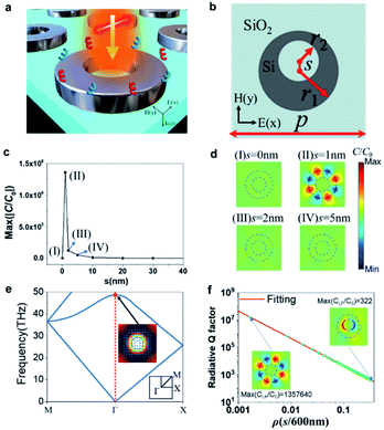 |
| | Fig. 1 (a) Scheme of the optomechanical separation of multiple paired enantiomers using an all-dielectric metasurface composed of the quasi-BIC MD meta-atom, where the metasurface is illuminated by linearly polarized (LP) light with E-field polarization along the x-axis. The enantiomers are positioned 20 nm above the metasurface residing on the SiO2 substrate. (b) The top view of a resonator with an off-centered hole with r1 = 1200 nm, r2 = 600 nm, s = 1 nm. The period of the metasurface is p = 4000 nm. The thickness of the Si nanodisk is t = 400 nm. (c) The off-set (s) dependent chirality density enhancement (C/C0). (d) The distributions of C/C0 in the resonator with the off-sets of s = 0, 1, 2, and 5 nm. (e) Band structure associated with the BIC MD resonance. Inset: the EM-field distribution of the BIC MD mode in a meta-atom, in which the color shows the intensity of the H-field, and the blue arrows indicate the vector of in-plane E-field. The meta-atom is circled by the purple dashed line. (f) Dependence of the radiative Q factor (Qr) on the asymmetry parameter (ρ). The red line presents an inverse quadratic fitting. Inset: the top view of the distribution of the chirality enhancement (C/C0) for the quasi-BIC MD resonance (ρ = 0.00167) and normal FR (ρ = 0.33). | |
In Fig. 1c, the C/C0 is calculated to evaluate the chirality enhancement through the quasi-BIC MD resonance. With increasing s from 0 to 40 nm, the C/C0 obtains the largest enhancement factor of 1.36 × 10⁶ at s = 1 nm. Therefore, in our simulation, the resonator is optimized at s = 1 nm. In Fig. 1d, we demonstrate the distributions of chirality density enhancement C/C0 in the resonator with the off-sets of s = 0, 1, 2, and 5 nm, together with the simulated transmittance spectra shown in ESI Fig. S2.† It is obvious that changing the s allows for direct control on the quality (Q) factor of the dip resonance in the transmittance spectrum, which can drastically engineer the intensity of the chirality of the system. As is seen, the largest enhanced chiral field can be obtained at s = 1 nm for λ = 6203 nm. These enhanced chiral fields are confined along the outer edge of the Si nanodisk where the largest cos(θiE,H) appears (see ESI Fig. S1d†).
By introducing an asymmetry to the system that supports a symmetry-protected BIC, a pure BIC can be transformed to a quasi-BIC. For instance, by introducing an off-centered hole in the Si nanodisk, it is possible to open a radiation channel of the BICs in our proposed metasurface and transform the BIC state into a quasi-BIC state. In Fig. 1e, we calculate the band structure of the transverse electric (TE) mode for the symmetric metasurface made of an array of the Si nanodisk penetrated by a centered hole. Initially, the BIC response is produced by the symmetric Si rings supporting the MD resonance at the Γ point of the first Brillouin zone. By embedding the off-centered hole into the Si nanodisk to break the symmetry of the structure, we can change the BIC MD state possessing an infinite Q-factor to the quasi-BIC MD state with a finite Q-factor. The EM-field distribution of the eigenmode, presented in the inset of Fig. 1f, explores the MD feature of the BIC state. Moreover, other than the traditional confined guided modes supported by the periodic structure that is under the light cone, the BIC-inspired method permits directly exciting the quasi-BIC MD modes by free transmitting plane waves, enabling it to be a much more flexible platform for nanophotonics applications. In the real experiment, the Q-factor is composed of the nonradiative part Qnr and radiative part Qrvia 1/Q = 1/Qnr + 1/Qr. In particular, the Qnr includes a disorder of the structure, roughness of surface, the variation of fabricated device from the design, among others. The Q-factors of most dielectric metasurfaces under normal excitation are as small as a few thousand caused by the small Qnr in the optical region. It has hugely hampered the exploitation of novel physics under intensely enhanced light-matter interference and their applications for opto-mechanics. In order to excite a MD resonance with high-Q factor under a normal excitation, one needs to break the symmetry of the system to transit the resonant mode from the BICs to quasi-BICs. With a lower degree of asymmetry, a larger Qr is obtained.38,69 Thus, the ultrasmall degree of asymmetry is important for realizing high-Q quasi-BICs. Herein, the evolution of the quasi-BIC Qr on the asymmetry parameter (ρ = s/600 nm) of the resonator follows the clearly inverse quadratic law,38 as presented in Fig. 1f,
where
Q0 is a constant decided by the design of the metasurface independent with
ρ. For the bigger
ρ, the decrease of
Qr becomes faster because the deviation from the symmetric resonator is not treated as a small perturbation.
70 By means of the quasi-BIC mechanism, the radiation damping rate can be engineered in a straightforward way. Hence, the width of the resonance that vanishes ideally when the symmetry of the structure is not broken. Thus, the quasi-BICs resonance provides an efficient way to tailor the
Q-factor as required. In particular, at
ρ = 0, the BIC mode is symmetry protected and not manifested in the transmittance spectrum (black solid line in ESI Fig. S2
†). By slightly breaking the symmetry of the metasurface (
i.e.,
ρ = 0.00167,
s = 1 nm), the metasurface allows for obtaining an energy exchange with the external modes, and manifests itself as a sharp Fano feature relating to a quasi-BIC with high
Q-factor of 1.6 × 10
7 in the optical regime (red solid line in ESI Fig. S2
†). In the insets of
Fig. 1f, we demonstrate the distributions of
C/
C0 for quasi-BIC MD resonance (
ρ = 0.00167) and normal Fano resonance (
ρ = 0.33). As is seen, the
C/
C0 achieved by the quasi-BIC MD resonance is four orders larger compared to the normal Fano resonance (FR). Moreover, the eight lobes with interchanging sign of
C/
C0 around the disk only occurs for the quasi-BIC MD resonance. As a straightforward application, we have demonstrated the extremely efficient separation of sub-2 nm enantiomers with tiny chirality (
κp = ±0.01) and even observed the high-throughput separation of four paired enantiomers in the high-
Q quasi-BIC MD metasurface.
2.2. Sorting of four paired enantiomers using quasi-BICs enhanced lateral force
A chiral particle immersed in an external EM field can be simulated as a magnetoelectric dipole69 with a coupled ED moment (P), and MD moment (M). The particle response owing to the EM field is determined by the interference between the EM field and combined system of the scalar electric (α), magnetic (β), and hybrid magnetic–electric (χ) polarizabilities, shown in ESI eqn (S1).† Within the electric dipole approximation, when the size of the considered particles with the various shapes (i.e., helix or sphere) is significantly smaller than the wavelength of the incident light, they can all be simulated as a magnetoelectric dipole with a coupled electric dipolar moment and magnetic dipolar moment.71,72 The time-averaged resultant lateral force Ft on the chiral molecule is shown bywhere the paired enantiomers with the opposite handedness endure the achiral gradient forces Fα,β with the same magnitude and direction, and the chiral gradient force Fχ with the opposite directions. To optically separate the enantiomers, a local region is required to create the strong chirality offering a giant Fχ, while decreasing the energy density gradients to induce a tiny Fα,β. In this way, the Fα,β can be dominated by the Fχ, enabling the Ft to sort the handedness of the paired enantiomers.30 Herein, we neglect perturbations of the gradient fields induced by the nanosized chiral particle due to its ultra-short radius of rp ≪ λ/20. In our numerical model, the targeted chiral molecule is mimicked by a nanosphere with a radius of rp = 2 nm, refractive index of np = 1.44, and a chirality (κp) ranging from −0.01 to +0.01, with the plus (+) and minus (−) signs standing for the enantiomers with right-handedness (RH) and left-handedness (LH), respectively. The κp determines the level of handedness of the chiral molecules, and its imaginary part is neglected by presuming Re(κp) ≫ Im(κp).14,28 The particle is immersed in a refractive-index-matching liquid to meet the dual-symmetry conditions28 (np = ns = 1.44) and the incident source intensity is 100 mW μm−2. To confirm the key role of Fχ in the enantioseparation, Fig. 2a–c show Fα,β, Fχ, and Ft on the chiral nanoparticles at λ = 6203 nm (quasi-BIC mode). To explore the possibility of high-throughput enantioseparation using the nanostructure, four paired enantiomers with κp = ±0.01 are located 20 nm above the center of the meta-atom. As is observed, the Fα,β was the same for the enantiomers with the opposite handedness (Fig. 2a), ruining the performance of the enantioseparation. However, owing to the large chirality enhanced by the quasi-BIC MD resonance, Fχ can be swapped by varying the handedness of the target object that is significantly larger than Fα,β (Fig. 2b). The left column of Fig. 2c shows that for the left-handedness (LH) enantiomer, the maximum Ft was ∼0.57 pN, which drags the four LH-enantiomers toward the outer edge of the Si nanodisk. As can be seen in the right column, the Ft on the right-handedness (RH) enantiomer can also reach ∼0.59 pN and pull the other four RH-enantiomers to the outer edge. Finally, the eight LH and RH enantiomers can be trapped alternatively at the azimuth angle interval of 45° along the outer edge of the Si disk (see further discussion in Fig. 3). A detailed description of the calculation of lateral forces (i.e., Fχ, Fα,β, and Ft) can be found in the ESI.†
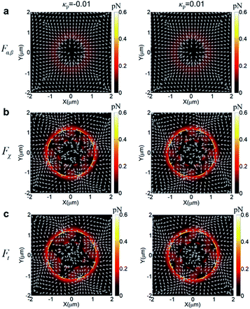 |
| | Fig. 2 The lateral forces on the four paired enantiomers positioned 20 nm above the center of the quasi-BIC MD resonator at λ = 6203 nm with the LP incidence. The gray arrows stand for the direction of the forces. (a) The achiral gradient force Fα,β; (b) the chiral gradient force Fχ; and (c) the resultant lateral force Ft on the four paired enantiomers with LH (left column) and RH (right column) chirality. | |
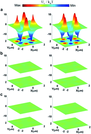 |
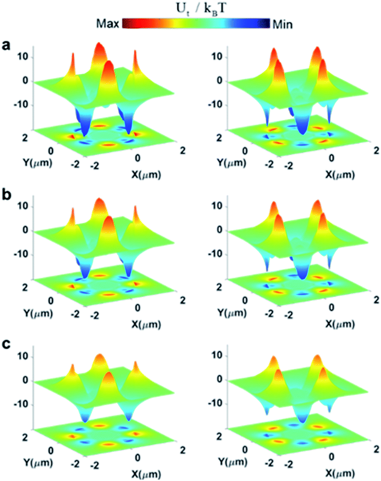
| | Fig. 3 Surface potential (Ut) under an illumination of linearly polarized light for the LH- (κp = −0.01) and the RH- (κp = +0.01) enantiomers with rp = 2 nm at 20 nm above the surface of the quasi-BIC MD meta-atom with (a) s = 1 nm, (b) s = 2 nm, (c) s = 5 nm, respectively. | |
2.3. The chirality-dependent potential well for enantiomers positioned at 20 nm above the meta-atom
In the model, the nanoscale chiral entities can move from infinity to the outer edge of the Si nanodisk for Ut < 0, or from the outer edge to infinity for Ut > 0. The pronounced variation in Ft for the paired enantiomers with the opposite handedness can significantly alter the Ut. Fig. 3a shows the 3D perspective visions of the calculated 2D potential surface around the chiral nano-objects (rp = 2 nm) with κp = +0.01 (left column) and κp = −0.01 (right column), respectively, placed 20 nm above the resonator with s = 1 nm at λ = 6203 nm. The Si disk produces Ut for the enantiomer around the outer edge, and this Ut varies the sign at each octant of the x–y plane normal to the incident wave. It is noteworthy that Ut is reversed at the same place for the enantiomer with opposite handedness. For example, as is observed in the left column, the deep minus Ut (Ut = −13kBT) can trap the LH-enantiomer into the four positions around the outer edge of the Si disk with an azimuth angle interval of 90°, while swapping its direction to push the RH-enantiomer away. That is, the intensely positive Ut (Ut = +12kBT) builds up a large potential barrier that forbids the RH-enantiomer from flowing toward the same position, thus achieving a separation of the paired enantiomers. However, the RH-enantiomer can be captured into the neighboring octant where the Ut is −13kBT for the RH-enantiomer (right column). Such unique distribution of optical potential may enable a high throughput separation of the four paired enantiomers. Fig. 3b and c present the Ut on the LH- (left column) and RH (right column)-handed chiral particle placed 20 nm above the resonator with s = 2 and 5 nm, around λ = 6203 nm, accordingly. As is seen, the Ut on the nanoparticles (rp = 2 nm, κp = ±0.01) were decreased significantly that cannot separate the enantiomeric pair due to the absence of the quasi-BIC MD resonance.
2.4. The trajectories for the sub-2 nm enantiomers with the different chirality κp
| |
| (5) |
| |
| (6) |
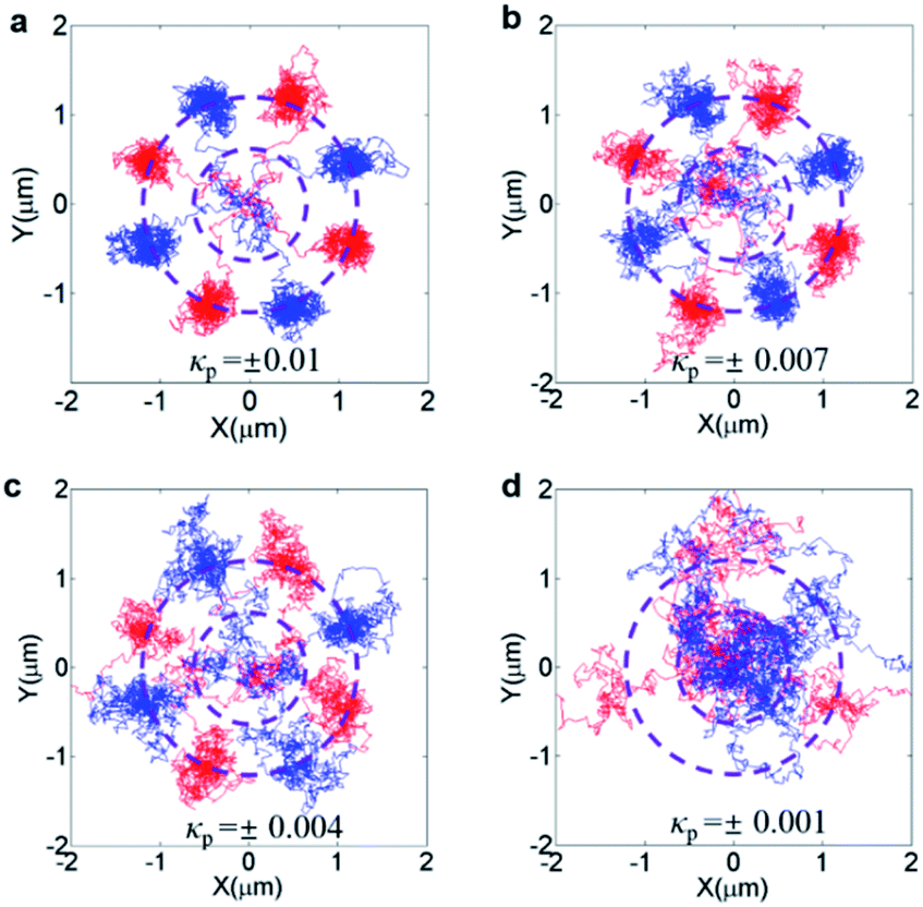
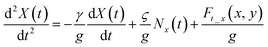
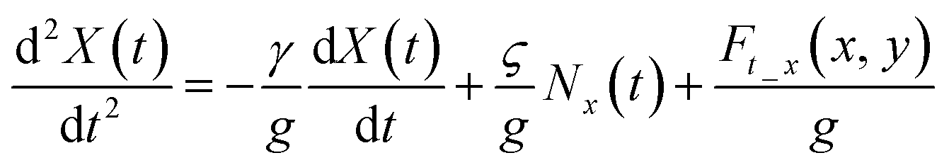
where Ft_x(x, y) and Ft_y(x, y) represent the transverse forces, X(t) and Y(t) represent the locations of chiral objects, Nx(t) and Ny(t) represent the stochastic noise terms adopted to simulate the random collisions from fluid objects along both x- and y-axes, respectively, g is the mass of specimen, γ = 6πβ(rp) is the drag coefficient where the viscosity of the surrounding media is β = 0.89 mPa s and the radius of the chiral particle is rp = 2 nm.  represents the scaling constant for the stochastic noise term. Herein, we have ignored the influence of the optical force along the z-direction on the motion of the specimen that can reduce the complicacy of the model. Fig. 4a presents a dynamic simulation of the stability of four paired enantiomers (κp = ±0.01) by plotting the particles' trajectories above the quasi-BIC MD resonator. The sub-2 nm chiral entities exhibiting the different handedness in the x–y plane are traced with an accuracy of “nm”. The 10 ms trajectories of the four LH-enantiomers with κp = − 0.01 are shown in the blue lines. The four LH-enantiomers move toward the four octants along the outer edge of the Si nanodisk under the interval of the azimuth angle of φ = 90°, in which the negative trapping potential of Ut = −13kBT occurs (Fig. 3a). On the contrary, the other four RH-enantiomers (κp = +0.01) are dragged toward the remaining four octants (see the red lines) by the negative trapping potential of Ut = −13kBT (Fig. 3b). This is because the total lateral force on the enantiomers with the opposite handedness is applied in different directions (Fig. 2c). The dynamic motions of the four paired enantiomers (κp = ±0.01) are also recorded in ESI Movie S1.† As is seen, the LH- and RH- enantiomers can be stably and alternatively trapped at the outer edge of the Si nanodisk at the end of 10 ms. Although this video may not precisely present the experimental data, it was obtained based upon the particles' movements modeled by the stochastic differential equations.73 Exploring their movements offered insight into the nanoparticle's out-of-equilibrium phenomena, and stochastic differential equations can mathematically model their movements, such as funneling, trapping, and sorting.74,75Fig. 4b–d further present the stability of the four paired enantiomers with the various κp. It indicates that the metasurface cannot divide the paired enantiomers with κp = ±0.001. In ESI Fig. S4,† it shows that the depth of Ut on the enantiomers with κp = ±0.001 is smaller than 10kBT that cannot overcome Brownian motion of the nanoobjects in water. To this end, in ESI Fig. S5,† we further explored the effect of the illumination intensity (Iin) on the trajectories of the paired enantiomers. As is observed, the larger Iin is, the paired enantiomers with smaller κp can be separated stably. Namely, our structure can sort the enantiomers with κp = ±0.001 by increasing the Iin from 100 mW μm−2 to 500 mW μm−2, accordingly. Moreover, it has been experimentally demonstrated that a very small temperature increase of 1.45 °C/100 mW was observed when the vesicles were held stationary with a 1.064 μm optical tweezer having a power density of 103 mW μm−2 and a focused spot size of 0.8 μm.76,77 These works showed that the light intensity ranging from 100 to 500 mW μm−2 could be endured by the meta-atoms and particles. Recently, aberration-corrected electron-beam lithography (AC-EBL) has employed an optical system designed to produce atomic resolution images at the Angstrom length scales, enabling 1 nm-scale patterning resolution.78 This AC-EBL technique can be used to make our proposed metasurface. Transmission spectral scans using a tunable external cavity laser (calibrated by a separate interferometer) can be used to experimentally evaluate the Q-factor.79–81 The optical sorting system can be subsequently realized by integrating the microfluidic channel on top of the metasurface. The nanometer enantiomers were placed inside the microfluidic channel containing water. Herein, the nanometer enantiomers can be commercially available fluorescently-labeled chiral drugs, such as atorvastatin, clopidogrel and apoetin alpha.82 Meanwhile, a more realistic value of the off-set (s) was considered in ESI Fig. S6.† It was shown that the Si metasurface with s = 20 nm can significantly increase the chirality density to C/C0 = 3631 (ESI Fig. S6(a)†), enabling an enantioseparation of the paired chiral entities with a radius of 14 nm (ESI Fig. S6(b)†).
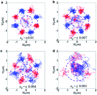 |
| | Fig. 4 The stability of the enantiomeric pair (rp = 2 nm), where the red and blue solid lines represent the 10 ms trajectories of the LH- and RH-enantiomers, respectively, (a) κp = ±0.01, (b) κp = ±0.007, (c) κp = ±0.004, (d) κp = ±0.001. | |
Since our sorting strategy relied on the near-field effect, it was important to investigate Ut for enantiomers that were located at different distances above the metasurface. In Fig. 5, we have presented the Ut around the enantiomeric pair (rp = 2 nm) with κp = +0.01 (left column) and κp = −0.01 (right column), respectively, positioned at different distances above the meta-atom under an illumination of linearly polarized light. The magnitude of Ut was reduced with increasing distance between the enantiomers and metasurface. The stable trapping can be achieved by placing the enantiomers within 30 nm above the metasurface, where the magnitude of Ut was larger than 10kBT. Although Ut can obtain the maximum value just on the surface of the meta-atom, the particle-surface force interaction may induce a strong dispersion force that damages the optical sorting of the molecules.83 Therefore, we placed the particle 20 nm above the surface of metasurface.
 |
| | Fig. 5 Surface potential (Ut) under an illumination of linearly polarized light for the LH- (κp = −0.01) and the RH- (κp = +0.01) enantiomers with rp = 2 nm at the different distances of (a) Z = 2 nm, (b) Z = 10 nm, (c) Z = 30 nm above the surface of the quasi-BIC MD meta-atom. | |
3. Conclusions
In summary, we demonstrate that an all-dielectric metasurface composed of Si nanodisk arrays can excite high Q-factor associated with quasi-BIC. We also investigated the probability of high-throughput chiral sorting using this dielectric metasurface under an illumination of linearly polarized light. The Si nanodisk embedded with an off-centered hole was used to generate the quasi-BIC MD resonance, which can pronouncedly enhance the chirality density gradient with alternating sign at each octant around the disk, while upholding a small gradient for the EM density. This provides enantioselective resultant lateral forces and potential wells that can efficiently separate four pairs of sub-2 nm enantiomers with tiny chirality parameter of ±0.01 that was previously inaccessible. Our contribution may allow for efficiently designing novel enantioselective metadevices with a discriminatory capability of sub-2 nm chiral objects and very small chirality parameter.
4. Methods
4.1. Calculation of optical forces
We have numerically simulated the electromagnetic (EM−) field profile and optical force distribution in the x–y plane 20 nm above the metasurface using the finite element method (FEM) solver in CST MICROWAVE STUDIO® (MWS) integrated with MATLAB. Namely, the CST Studio was employed to calculate the light field (Ex, Ey, Ez, Hx, Hy, Hz). MATLAB was subsequently used to calculate the optical force on the molecule using ESI eqn (S1)–(S10).† The tetrahedral mesh was employed in the model. The minimum and maximum mesh sizes were 0.5 nm and 5 nm, respectively. The periodic boundary condition was applied in the x–y plane and a perfectly matched layer boundary condition was used along the z-axis. In the model, we considered the intrinsic loss of the silicon.84
Author contributions
Tun Cao conceived the idea and supervised the project. Libang Mao and Kuan Liu conducted the simulation. Pei-yuan Cheng and Meng Lian analyzed the data. Tun Cao and Libang Mao co-wrote the manuscript. All authors have given approval to the final version of the manuscript.
Conflicts of interest
There are no conflicts to declare.
Acknowledgements
This research is supported by the National Key Research and Development Program of China (2020YFA0714504, 2019YFA0709100).
References
- R. J. Cronin, Science, 1997, 275, 951–955 CrossRef PubMed.
- R. Mckendry, M. E. Theoclitou, T. Rayment and C. Abell, Nature, 1998, 391, 566–568 CrossRef CAS.
- Anonymous, Chirality, 1992, 4, 338–340 CrossRef PubMed.
- H. Gabriel, B. U. Monica, M. D. Lucia, G. Laszlo and R. Aura, Biomed. Chromatogr., 2018, e4335 Search PubMed.
- H. Zhong, B. Zhao and J. Deng, Nanoscale, 2021, 11765–11780 RSC.
- M. Van der Verren, V. Smeets, A. vander Straeten, C. Dupont-Gillain and D. P. Debecker, Nanoscale Adv., 2021, 3, 1646–1655 RSC.
- G. Gübitz and M. G. Schmid, Biopharm. Drug Dispos., 2001, 22, 291 CrossRef PubMed.
- T. Zhang, M. R. C. Mahdy, Y. Liu, J. H. Teng, C. T. Lim, Z. Wang and C.-W. Qiu, ACS Nano, 2017, 11, 4292–4300 CrossRef CAS PubMed.
- M. Wang, H. Li, D. Gao, L. Gao, J. Xu and C.-W. Qiu, Opt. Express, 2015, 23, 16546–16553 CrossRef CAS PubMed.
- X. Tang, F. Nan and Z. Yan, Nanoscale Adv., 2020, 2, 2540–2547 RSC.
- A. Devi, S. S. Nair, S. Yadav and A. K. De, Nanoscale Adv., 2021, 3, 3288–3297 RSC.
- G. Tkachenko and E. Brasselet, Nat. Commun., 2014, 5, 1–7 Search PubMed.
- Y. Shi, T. Zhu, T. Zhang, A. Mazzulla, D. P. Tsai, W. Ding, A. Q. Liu, G. Cipparrone, J. J. Sáenz and C.-W. Qiu, Light: Sci. Appl., 2020, 9, 1–12 CrossRef PubMed.
- M. Alizadeh and B. r. M. Reinhard, ACS Photonics, 2015, 2, 361–368 CrossRef CAS.
- M. Li, S. Yan, Y. Zhang, X. Chen and B. Yao, Nanoscale Adv., 2021, 6897–6902 RSC.
- Y. Tang and A. E. Cohen, Science, 2011, 332, 333–336 CrossRef CAS PubMed.
- X. Mu, L. Hu, Y. Cheng, Y. Fang and M. Sun, Nanoscale, 2021, 13, 581–601 RSC.
- B. Ai, H. M. Luong and Y. Zhao, Nanoscale, 2020, 12, 2479–2491 RSC.
- X. Lu, J. Wu, Q. Zhu, J. Zhao, Q. Wang, L. Zhan and W. Ni, Nanoscale, 2014, 6, 14244–14253 RSC.
- K. Yao and Y. Liu, Nanoscale, 2018, 10, 8779–8786 RSC.
- F. Fan, C. Zhong, Z. Zhang, S. Li and S. Chang, Nanoscale Adv., 2021, 3, 4790–4798 RSC.
- A. A. Saleh and J. A. Dionne, Nano Lett., 2012, 12, 5581–5586 CrossRef CAS PubMed.
- J. Berthelot, S. S. Aćimović, M. L. Juan, M. P. Kreuzer, J. Renger and R. Quidant, Nat. Nanotechnol., 2014, 9, 295–299 CrossRef CAS PubMed.
- G. C. Messina, X. Zambrana-Puyalto, N. Maccaferri, D. Garoli and F. De Angelis, Nanoscale, 2020, 12, 8574–8581 RSC.
- Y. Zhang, J. Shen, Z. Xie, X. Dou, C. Min, T. Lei, J. Liu, S. Zhu and X. Yuan, Nanoscale, 2017, 9, 10694–10700 RSC.
- S. Wang and C. Chan, Nat. Commun., 2014, 5, 1–8 Search PubMed.
- T. Zhu, Y. Shi, W. Ding, D. P. Tsai, T. Cao, A. Q. Liu, M. Nieto-Vesperinas, J. J. Sáenz, P. C. Wu and C.-W. Qiu, Phys. Rev. Lett., 2020, 125, 043901 CrossRef CAS PubMed.
- Y. Zhao, A. A. Saleh and J. A. Dionne, ACS Photonics, 2016, 3, 304–309 CrossRef CAS.
- H. A. A. Champi, R. H. Bustamante and W. J. Salcedo, Opt. Mater. Express, 2019, 9, 1763–1775 CrossRef CAS.
- T. Cao, L. Mao, Y. Qiu, L. Lu, A. Banas, K. Banas, R. E. Simpson and H. C. Chui, Adv. Opt. Mater., 2019, 7, 1801172 CrossRef.
- T. Cao and Y. Qiu, Nanoscale, 2018, 10, 566–574 RSC.
- C. W. Hsu, B. Zhen, J. Lee, S. L. Chua, S. G. Johnson, J. D. Joannopoulos and M. Soljacic, Nature, 2013, 188–191 CrossRef CAS PubMed.
- F. Ursell, Math. Proc. Cambridge Philos. Soc., 1951, 347 CrossRef.
- R. Parker, J. Sound Vib., 1966, 4, 62–72 CrossRef.
- D. Marinica, A. Borisov and S. Shabanov, Phys. Rev. Lett., 2008, 100, 183902 CrossRef CAS PubMed.
- J. von Neumann and E. Wigner, Phys. Z., 1929, 467 Search PubMed.
- H. Friedrich and D. Wintgen, Phys. Rev. A: At., Mol., Opt. Phys., 1985, 32, 3231 CrossRef CAS PubMed.
- K. Koshelev, S. Lepeshov, M. Liu, A. Bogdanov and Y. Kivshar, Phys. Rev. Lett., 2018, 121, 193903 CrossRef PubMed.
- F. Monticone and A. Alu, Phys. Rev. Lett., 2014, 112, 213903 CrossRef.
- K. Koshelev, A. Bogdanov and Y. Kivshar, Sci. Bull., 2019, 64, 836–842 CrossRef.
- J. M. Foley, S. M. Young and J. D. Phillips, Phys. Rev. B: Condens. Matter Mater. Phys., 2014, 89, 165111 CrossRef.
- M. Rybin and Y. Kivshar, Nature, 2017, 541, 164–165 CrossRef CAS PubMed.
- L. Carletti, K. Koshelev, C. De Angelis and Y. Kivshar, Phys. Rev. Lett., 2018, 121, 033903 CrossRef CAS PubMed.
- A. Tittl, A. Leitis, M. Liu, F. Yesilkoy, D.-Y. Choi, D. N. Neshev, Y. S. Kivshar and H. Altug, Science, 2018, 360, 1105–1109 CrossRef CAS PubMed.
- T. C. Tan, Y. K. Srivastava, R. T. Ako, W. Wang, M. Bhaskaran, S. Sriram, I. Al-Naib, E. Plum and R. Singh, Adv. Mater., 2021, 2100836 CrossRef CAS PubMed.
- S. Han, P. Pitchappa, W. Wang, Y. K. Srivastava, M. V. Rybin and R. Singh, Adv. Opt. Mater., 2021, 9, 2002001 CrossRef CAS.
- Y. K. Srivastava, R. T. Ako, M. Gupta, M. Bhaskaran, S. Sriram and R. Singh, Appl. Phys.
Lett., 2019, 115, 151105 CrossRef.
- S. Han, L. Cong, Y. K. Srivastava, B. Qiang, M. V. Rybin, A. Kumar, R. Jain, W. X. Lim, V. G. Achanta and S. S. Prabhu, Adv. Mater., 2019, 31, 1901921 CrossRef PubMed.
- L. Cong and R. Singh, Adv. Opt. Mater., 2019, 7, 1900383 CrossRef.
- C. B. R. Hurtado, J. Dickmann, F. F. Bruns, T. Siefke and S. Kroker, Opt. Express, 2020, 28, 20106–20116 CrossRef PubMed.
- Z. F. Sadrieva, I. S. Sinev, K. L. Koshelev, A. Samusev, I. V. Iorsh, O. Takayama, R. Malureanu, A. A. Bogdanov and A. V. Lavrinenko, ACS Photonics, 2017, 4, 723–727 CrossRef CAS.
- G. Corrielli, G. Della Valle, A. Crespi, R. Osellame and S. Longhi, Phys. Rev. Lett., 2013, 111, 220403 CrossRef CAS PubMed.
- M. I. Molina, A. E. Miroshnichenko and Y. S. Kivshar, Phys. Rev. Lett., 2012, 108, 070401 CrossRef PubMed.
- M. V. Rybin, K. L. Koshelev, Z. F. Sadrieva, K. B. Samusev, A. A. Bogdanov, M. F. Limonov and Y. S. Kivshar, Phys. Rev. Lett., 2017, 119, 243901 CrossRef PubMed.
- E. N. Bulgakov and A. F. Sadreev, Phys. Rev. B: Condens. Matter Mater. Phys., 2008, 78, 075105 CrossRef.
- I. Sakellari, E. Kabouraki, D. Karanikolopoulos, S. Droulias, M. Farsari, P. Loukakos, M. Vamvakaki and D. Gray, Nanoscale Adv., 2019, 1, 3413–3423 RSC.
- S. T. Ha, Y. H. Fu, N. K. Emani, Z. Pan, R. M. Bakker, R. Paniagua-Domínguez and A. I. Kuznetsov, Nat. Nanotechnol., 2018, 13, 1042–1047 CrossRef CAS PubMed.
- C. W. Hsu, B. Zhen, A. D. Stone, J. D. Joannopoulos and M. Soljačić, Nat. Rev. Mater., 2016, 1, 1–13 Search PubMed.
- N. Muhammad, Y. Chen, C.-W. Qiu and G. P. Wang, Nano Lett., 2021, 21, 967–972 CrossRef CAS PubMed.
- D. R. Abujetas, N. van Hoof, S. ter Huurne, J. G. Rivas and J. A. Sánchez-Gil, Optica, 2019, 6, 996–1001 CrossRef.
- L. Xu, K. Zangeneh Kamali, L. Huang, M. Rahmani, A. Smirnov, R. Camacho-Morales, Y. Ma, G. Zhang, M. Woolley and D. Neshev, Adv. Sci., 2019, 6, 1802119 CrossRef PubMed.
- J. Zhang, W. Liu, Z. Zhu, X. Yuan and S. Qin, Sci. Rep., 2016, 6, 38086 CrossRef CAS PubMed.
-
G. Subramanian and G. Subramanian, Chiral Separation Techniques, Wiley Online Library, 2000 Search PubMed.
-
E. D. Palik, Handbook of Optical Constants of Solids, Academic press, 1998 Search PubMed.
- S. Campione, S. Liu, L. I. Basilio, L. K. Warne, W. L. Langston, T. S. Luk, J. R. Wendt, J. L. Reno, G. A. Keeler and I. Brener, ACS Photonics, 2016, 3, 2362–2367 CrossRef CAS.
- J. C. Ginn, I. Brener, D. W. Peters, J. R. Wendt, J. O. Stevens, P. F. Hines, L. I. Basilio, L. K. Warne, J. F. Ihlefeld and P. G. Clem, Phys. Rev. Lett., 2012, 108, 097402 CrossRef PubMed.
- Y. Tang and A. E. Cohen, Phys. Rev. Lett., 2010, 104, 163901 CrossRef PubMed.
- M. Schäferling, X. Yin and H. Giessen, Opt. Express, 2012, 20, 26326–26336 CrossRef PubMed.
- A. S. Kupriianov, Y. Xu, A. Sayanskiy, V. Dmitriev, Y. S. Kivshar and V. R. Tuz, Phys. Rev. A, 2019, 12, 014024 CAS.
- K. Koshelev, Y. Tang, K. Li, D.-Y. Choi, G. Li and Y. Kivshar, ACS Photonics, 2019, 6, 1639–1644 CrossRef CAS.
- A. Hayat, J. B. Mueller and F. Capasso, Proc. Natl. Acad. Sci. U. S. A., 2015, 112, 13190–13194 CrossRef CAS PubMed.
- G. Pellegrini, M. Finazzi, M. Celebrano, L. Duò, M. A. Iatì, O. M. Maragò and P. Biagioni, J. Phys. Chem. C, 2019, 123, 28336–28342 CrossRef CAS.
- Y. Shi, S. Xiong, Y. Zhang, L. Chin, Y. Y. Chen, J. Zhang, T. Zhang, W. Ser, A. Larrson and S. Lim, Nat. Commun., 2018, 9, 1–11 CrossRef PubMed.
- G. Volpe, S. Gigan and G. Volpe, Am. J. Phys., 2014, 82, 659–664 CrossRef.
- Y. Zheng, J. Ryan, P. Hansen, Y.-T. Cheng, T.-J. Lu and L. Hesselink, Nano Lett., 2014, 14, 2971–2976 CrossRef CAS PubMed.
- Y. Liu, D. Cheng, G. Sonek, M. Berns, C. Chapman and B. Tromberg, Biophys. J., 1995, 68, 2137–2144 CrossRef CAS PubMed.
-
Y. Shi, Z. Li, D. P. Tsai, Y. Kivshar and A. Q. Liu, CLEO: Applications and Technology, Optical Society of America, 2021, JM4D. 5 Search PubMed.
- V. R. Manfrinato, F. E. Camino, A. Stein, L. Zhang, M. Lu, E. A. Stach and C. T. Black, Adv. Funct. Mater., 2019, 29, 1903429 CrossRef CAS.
- W. Jin, Q.-F. Yang, L. Chang, B. Shen, H. Wang, M. A. Leal, L. Wu, M. Gao, A. Feshali and M. Paniccia, Nat. Photonics, 2021, 15, 346–353 CrossRef CAS.
- D. Armani, T. Kippenberg, S. Spillane and K. Vahala, Nature, 2003, 421, 925–928 CrossRef CAS PubMed.
- A. Shitikov, I. Bilenko, N. Kondratiev, V. Lobanov, A. Markosyan and M. Gorodetsky, Optica, 2018, 5, 1525–1528 CrossRef CAS.
- A. Peepliwal, S. Bagade and C. Bonde, J. Biomed. Sci. Res., 2010, 2, 29–45 CAS.
- H. Yilmaz, K. Sato and K. Watari, J. Colloid Interface Sci., 2007, 307, 116–123 CrossRef CAS PubMed.
- E. Shkondin, O. Takayama, M. A. Panah, P. Liu, P. V. Larsen, M. D. Mar, F. Jensen and A. Lavrinenko, Opt. Mater. Express, 2017, 7, 1606–1627 CrossRef CAS.
Footnotes |
| † Electronic supplementary information (ESI) available. See DOI: 10.1039/d1na00764e |
| ‡ These authors contributed equally. |
|
| This journal is © The Royal Society of Chemistry 2022 |
Click here to see how this site uses Cookies. View our privacy policy here. 
 Open Access Article
 This Open Access Article is licensed under a Creative Commons Attribution-Non Commercial 3.0 Unported Licence
 *
*


![[thin space (1/6-em)]](https://www.rsc.org/images/entities/char_2009.gif) r = Q
r = Q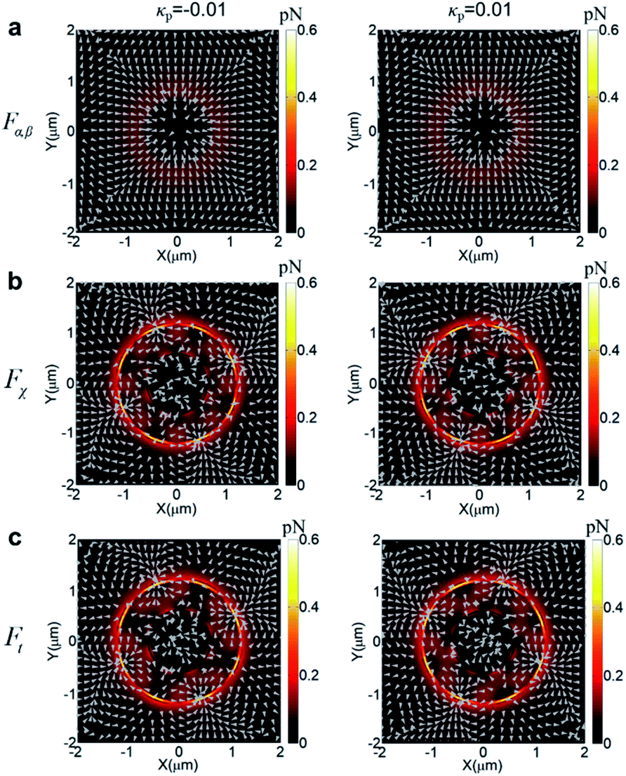


 represents the scaling constant for the stochastic noise term. Herein, we have ignored the influence of the optical force along the z-direction on the motion of the specimen that can reduce the complicacy of the model. Fig. 4a presents a dynamic simulation of the stability of four paired enantiomers (κp = ±0.01) by plotting the particles' trajectories above the quasi-BIC MD resonator. The sub-2 nm chiral entities exhibiting the different handedness in the x–y plane are traced with an accuracy of “nm”. The 10 ms trajectories of the four LH-enantiomers with κp = − 0.01 are shown in the blue lines. The four LH-enantiomers move toward the four octants along the outer edge of the Si nanodisk under the interval of the azimuth angle of φ = 90°, in which the negative trapping potential of Ut = −13kBT occurs (Fig. 3a). On the contrary, the other four RH-enantiomers (κp = +0.01) are dragged toward the remaining four octants (see the red lines) by the negative trapping potential of Ut = −13kBT (Fig. 3b). This is because the total lateral force on the enantiomers with the opposite handedness is applied in different directions (Fig. 2c). The dynamic motions of the four paired enantiomers (κp = ±0.01) are also recorded in ESI Movie S1.† As is seen, the LH- and RH- enantiomers can be stably and alternatively trapped at the outer edge of the Si nanodisk at the end of 10 ms. Although this video may not precisely present the experimental data, it was obtained based upon the particles' movements modeled by the stochastic differential equations.73 Exploring their movements offered insight into the nanoparticle's out-of-equilibrium phenomena, and stochastic differential equations can mathematically model their movements, such as funneling, trapping, and sorting.74,75Fig. 4b–d further present the stability of the four paired enantiomers with the various κp. It indicates that the metasurface cannot divide the paired enantiomers with κp = ±0.001. In ESI Fig. S4,† it shows that the depth of Ut on the enantiomers with κp = ±0.001 is smaller than 10kBT that cannot overcome Brownian motion of the nanoobjects in water. To this end, in ESI Fig. S5,† we further explored the effect of the illumination intensity (Iin) on the trajectories of the paired enantiomers. As is observed, the larger Iin is, the paired enantiomers with smaller κp can be separated stably. Namely, our structure can sort the enantiomers with κp = ±0.001 by increasing the Iin from 100 mW μm−2 to 500 mW μm−2, accordingly. Moreover, it has been experimentally demonstrated that a very small temperature increase of 1.45 °C/100 mW was observed when the vesicles were held stationary with a 1.064 μm optical tweezer having a power density of 103 mW μm−2 and a focused spot size of 0.8 μm.76,77 These works showed that the light intensity ranging from 100 to 500 mW μm−2 could be endured by the meta-atoms and particles. Recently, aberration-corrected electron-beam lithography (AC-EBL) has employed an optical system designed to produce atomic resolution images at the Angstrom length scales, enabling 1 nm-scale patterning resolution.78 This AC-EBL technique can be used to make our proposed metasurface. Transmission spectral scans using a tunable external cavity laser (calibrated by a separate interferometer) can be used to experimentally evaluate the Q-factor.79–81 The optical sorting system can be subsequently realized by integrating the microfluidic channel on top of the metasurface. The nanometer enantiomers were placed inside the microfluidic channel containing water. Herein, the nanometer enantiomers can be commercially available fluorescently-labeled chiral drugs, such as atorvastatin, clopidogrel and apoetin alpha.82 Meanwhile, a more realistic value of the off-set (s) was considered in ESI Fig. S6.† It was shown that the Si metasurface with s = 20 nm can significantly increase the chirality density to C/C0 = 3631 (ESI Fig. S6(a)†), enabling an enantioseparation of the paired chiral entities with a radius of 14 nm (ESI Fig. S6(b)†).