
 Open Access Article
 This Open Access Article is licensed under a
 Creative Commons Attribution 3.0 Unported Licence
Hierarchical nanoporous Ge anodes for lithium-ion batteries via plasma-phase-fabricated Mg2Ge†
Zhen
Fan
a,
Siobhan C.
Stevenson
a,
Alexander
Mungall
a,
Akira
Nishio
 b,
Robert
Szczęsny
c,
Yan-Gu
Lin
d,
Mark
Chen
e,
Wei-Ren
Liu
f,
Shigeto
Okada
b and
Duncan H
Gregory
*a
b,
Robert
Szczęsny
c,
Yan-Gu
Lin
d,
Mark
Chen
e,
Wei-Ren
Liu
f,
Shigeto
Okada
b and
Duncan H
Gregory
*a
aWestCHEM, School of Chemistry, University of Glasgow, Glasgow, G12 8QQ, UK. E-mail: Duncan.Gregory@glasgow.ac.uk; Tel: +44-141-330-8128
bInstitute for Materials Chemistry and Engineering, Kyushu University, 6-1, Kasuga-koen, Kasuga 816-8580, Japan
cFaculty of Chemistry, Nicolaus Copernicus University in Toruń, ul. Gagarina 7, 87-100 Toruń, Poland
dResearch Division, National Synchrotron Radiation Research Center, Hsinchu 30076, Taiwan
eAdvancharis Co. Ltd., Zhongshan Rd., Zhonghe Dist., New Taipei City 23557, Taiwan
fDepartment of Chemical Engineering, Chung Yuan Christian University, R&D Center for Membrane Technology, Research Center for Circular Economy, Research Center for Semiconductor Materials and Advanced Optics, 32023, No. 200, Chun Pei Rd., Chung Li District, Taoyuan City 32023, Taiwan
First published on 28th September 2022
Abstract
Deep reduction-magnesiation of GeO2 to Mg2Ge is achieved within 80 s via the microwave-induced-metal-plasma (MIMP) approach at 200 W in vacuo. A reaction mechanism can be proposed in which electrons function directly as reducing agents with germania. Almost simultaneously, interactions with electrons and Mgn+ cations promote the ultrafast nucleation of Mg2Ge. 3D hierarchical nanoarchitectures of Ge with coral-like structures and unique micro-meso-macro pore-distributions are then achieved by simple thermal dealloying of Mg2Ge in air. With outstanding porosity of almost 90%, as anodes in lithium-ion batteries (LIBs), the Ge matrices are pulverisation-tolerant during cycling, accommodating volume changes and releasing stress. Reliable stability, excellent rate capability and consistently high gravimetric capacity 2–3 times that of graphite, are characteristic features of the anodes. Our method offers great scope for the sustainable, scaled-up production of nanoporous materials from oxides.
Introduction
Sustainable energy conversion and storage is vital in a global context as the international community strives for a fossil fuel-free future.1–4 The discovery and development of materials that store/convert energy physiochemically is pivotal in fulfilling this ambition. The Zintl phase intermetallic Mg2Ge and antifluorite analogues such as Mg2Si and Mg2Sn have been heralded since the 1960s as impressive n-type thermoelectrics, with imposing mid-temperature performance (zT values exceeding unity).5,6 Their fundamental physical properties, e.g. thermal conductivity, electrical conductivity, band gaps, electronic structures and optical properties have been widely studied.5–8 These magnesium Zintl phases may also prove to be attractive precursors for dealloying and several intermetallic compounds/eutectic metal mixtures have been proposed for the scalable fabrication of nanoporous (NP) elemental matrices by this method.9 Mg2Ge is such a candidate for the facile fabrication of NP Ge, offering a tranche of potentially useful properties.10–16Stable, high capacity-high power density anode materials have aroused great interest in the design of next-generation LIBs given the limited specific capacity of graphite as a state-of-the-art commercial anode (372 mA h g−1) and restrictions on its safe operation at high currents.1–4 Alloying group 14 elements (e.g. Si, Ge, Sn) are appealing alternatives.11,12,17 Despite unfavourable comparisons with Si (∼4199 mA h g−1 for Li4.4Si), the capacity of Ge remains impressive (∼1624 mA h g−1 for Li4.4Ge) and Ge enjoys both superior electrical conductivity (100 times greater) and Li+ transport (400 times faster) vs. Si.10–14,17 The pseudo-isotropic lithiation and swelling of Ge can help avoid stress failures on cycling,13–15 but Ge still undergoes a huge volume expansion (∼300%) on its lithiation to Li4.4Ge. Repeated volume changes during cycling can cause the pulverisation of active materials, continuous (re)formation of a solid–electrolyte interface (SEI), and aggregation of Ge particles, leading to poor electrical contact, restricted Li+ diffusion, and depletion of electrolyte to result in capacity fade and/or cell failures, representing a huge technological challenge for the application of bulk Ge in LIBs.13–16 SEI design/optimisation has been recently reported to be an effective strategy to improve Ge anodes. Common electrolyte additives (e.g. vinylene carbonate (VC), fluoroethylene carbonate (FEC)) are employed with surface-modified Ge-nanomaterials to form a thin, flexible and robust SEI with improved ionic conductivity.18–20 Similarly, SEI engineering via ultra-conformal Sb coating onto nanoporous (NP) Ge or by melamine coating onto Ge nanoparticles has led to stable performance at high currents over extended cycling.18,19
Indeed, prior nanostructuring had already become the established approach to Ge anode design and underpins the additive-focused methods above, by forming nano-particles, -wires, -tubes, and -porous structures of Ge and its composites,13,15,21–25 and recently Ge–Si/(–Cu) nanowires have been anchored directly onto current collectors.12,26,27 Surface coating or confinement methods can enhance the structural stability, helping to mediate large volume changes and improve cycling performance.13–16,21–27 The established synthesis approaches, however, can be complicated with certain requirements imposed by precursors and/or equipment, limiting the likelihood of upscaling production.13–16,21–28 High surface area 3D NP materials containing “nano-ligaments” that can accommodate volume changes and increase electrolyte access via nanopores, however, represent a promising development.13,28–32 NP Ge can exhibit high capacity and stability even without surface modification and shows potential for scaled-up fabrication. For example, NP Ge fabricated by dealloying eutectic Al–Ge, Al–Ge–Ag or Al–Ge–Si alloys in acid solutions have delivered stable, high capacities over 100 cycles.33–35 A simpler, inexpensive route to NP Ge from readily available GeO2, rather than from eutectic Ge-alloys however, would be a considerable advance.14 Dual-porous nanostructures of Ge were synthesised by a 2-step zinc reduction followed by HF etching from GeO2–SiO2 nanocomposites, showing excellent anode performance for up to 300 cycles.36 Alternatively, Ge could be reduced from GeO2 using flowing hydrogen under carefully controlled high temperature regimes for >10 h and showed high reversible capacity in LIBs.15 Although both these synthesis routes produce useful Ge anodes, the preparation methods required are not necessarily simple, safe or sustainable.
Approaches to fabricate NP Ge from GeO2 remain rather elusive. Indeed, the Ge microstructure and morphology varies for different synthesis methods, which in turn influences properties.12,15,21,28,36,37 Further, the need for synthesis to be sustainable and energy-efficient has become an important demand for 21st century chemistry.5,9,38 Such considerations need to be factored into the production of (nano-structured) Ge anodes.10–17 Herein, we adopt the concept of microwave-induced-metal-plasma (MIMP) synthesis for the reduction of Ge(IV) in GeO2 to nominal Ge (−IV) in Mg2Ge in only 80 s at 200 W under vacuum (Scheme 1). The unique and ultra-fast reduction and magnesiation of GeO2 may benefit from non-thermal effects of Mg plasma, i.e. highly mobile electrons directly reduce the oxide while the spontaneous nucleation of Mg2Ge could be promoted by “bombarding” Ge with both electrons and Mgn+ cations. The Mg2Ge powders can then undergo a facile thermal dealloying treatment in air,10 which yields 3D hierarchical nanostructures of Ge with a porosity of 88.62% after washing. The large-surface area (17.82 m2 g−1) coral-like structure is composed of spherical and lamellar nano-ligaments (measuring from ca. 2–70 nm) which engender a wide distribution of micro-, meso- and macropores across length scales (from <2 to <200 nm). These features encouraged us to test the raw NP Ge material as an anode for LIBs allowing us to compare it to similar established electrodes with and without further modifications. The unique structural features created by this process enable NP Ge to deliver both high capacity and good stability when cycling at 1 A g−1 or 2 A g−1, indicating exceptional intrinsic rate capability as anodes in LIBs. These might be improved still further by subsequent electrode and cell optimisation.
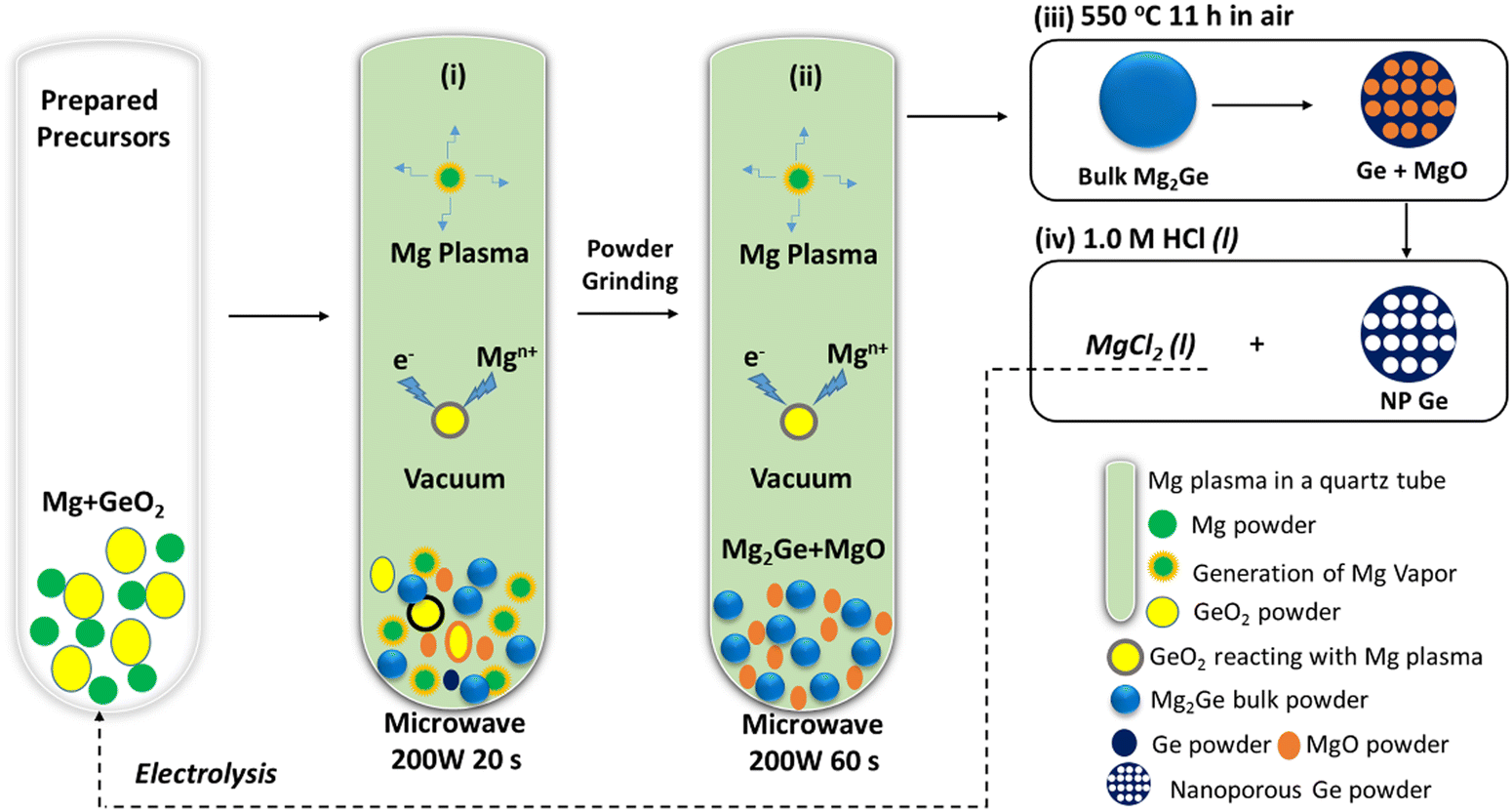 | ||
| Scheme 1 Schematic of the MIMP-assisted synthesis of hierarchical NP Ge from GeO2, showing: (i)–(ii) steps of the MIMP synthesis process; and (iii)–(iv) steps of the thermal dealloying and purification processes. | ||
Results and discussions
Ultra-fast MIMP-approach for reduction-magnesiation of GeO2 to Mg2Ge
The sustainable, energy-efficient synthesis of materials has been a priority for 21st century manufacturing.5,11,25,38 Previously, we conceived the MIMP method for the synthesis of alloys from metals, by which ultra-rapid reactions were driven by metal plasma interactions in a 2.45 GHz electromagnetic field.5,9,39 Here, we first show how the concept can be applied to the conversion of an oxide (GeO2) directly to an alloy (Mg2Ge) by a MW-induced Mg plasma (Scheme 1; see also the experimental Section; full details in the ESI†). Mixtures of fine Mg and GeO2 powders were irradiated by MWs (200 W) in a single-mode cavity reactor under a static vacuum of 1.0 × 10⁻¹ mbar. A green Mg plasma – which can be conceived as positively charged Mg cations, metastable neutral Mg clusters and negatively charged electrons5,9,39 – was observed within seconds of the onset of MW irradiation (ESI,† Supporting Videos 1, 2), indicating efficient ohmic coupling of the Mg powders with MWs. Ex situ powder X-ray diffraction (PXD) patterns (Fig. 1) indicate that most of the GeO2 and Mg reacted to form Mg2Ge under irradiation for only 20 s (with the MgO by-product and a trace amount of Ge present; Fig. S2 and Table S9, ESI†). The powdered reactant/product mixture was then reground and irradiated for a further 60 s (i.e. 80 s total), whereupon Mg plasma (from remaining unreacted Mg) completed the reduction of residual GeO2 and reacted with Ge to form Mg2Ge (with only MgO by-product otherwise remaining; Fig. 1 and Fig. S1, Table S8, ESI†). | ||
| Fig. 1 PXD patterns of samples: (i) after the 1st MW irradiation of 20 s, (ii) after the 2nd MW irradiation of 60 s, and (iii) after thermal dealloying (in air) at 550 °C for 11 h. (See synthesis steps in Scheme 1, for reference.). | ||
Thus, the ultra-fast, energy-efficient conversion of GeO2 into Mg2Ge can be achieved in under 1.5 min via MIMP synthesis. Apart from the small amount of Ge present after 20 s, no evidence for the formation of any other intermediate phases was observed. Hence, the reaction appears to follow relatively straightforward reduction-magnesiation steps without the formation of volatile GeO – an intermediate in both the conventional carbothermal reduction and hydrogen reduction of GeO2.40–42“Control” reactions employing lower ratios of Mg![[thin space (1/6-em)]](https://www.rsc.org/images/entities/char_2009.gif) :GeO2 (ca. 2.5:1) confirmed reduction to Ge without detectable prior formation of GeO (Fig. S3 and S5, ESI†). However, in every case, these reactions also led to the formation of Mg2Ge rather than to the complete reduction of GeO2 to Ge, suggesting the magnesiation (“deep reduction” to nominal Ge(−IV) in Mg2Ge) is kinetically favoured.
:GeO2 (ca. 2.5:1) confirmed reduction to Ge without detectable prior formation of GeO (Fig. S3 and S5, ESI†). However, in every case, these reactions also led to the formation of Mg2Ge rather than to the complete reduction of GeO2 to Ge, suggesting the magnesiation (“deep reduction” to nominal Ge(−IV) in Mg2Ge) is kinetically favoured.
At this point we can consider the mechanism of the deep-reduction reaction between relatively thermodynamically stable, solid germania and metastable Mg plasma in an electromagnetic field.15,40–42 In forming a plasma, Mgn+ cations lose electrons and are effectively not themselves reductive. The much lighter electrons within the plasma exhibit much higher speeds than these Mgn+ cations.5 The “free” electrons themselves, can potentially function as reducing agents by interacting directly with the solid GeO2. Meanwhile, the participation of the mobile plasma-phase Mgn+ cations facilitates the ultra-fast nucleation of Mg2Ge (and also of MgO with available oxygen). Notably, the reaction of Mg with GeO2 begins within seconds of initial irradiation and the deep reduction of GeO2 by Mg to Mg2Ge is well progressed after the first irradiation cycle (Fig. 1). It is these rapid reactions and the plasma concentrated in the vicinity of the sample (ESI,† Supporting Videos 1,2) that would appear to preclude the formation and sublimation of GeO. The monoxide is a regular by-product in the much slower high temperature carbothermal and hydrogen reductions of GeO2.15,40–42 Although reaction in the solid state cannot be completely excluded given the elevated temperature inside the reaction tube (facilitating solid state ionic diffusion), we propose that the ultra-rapid deep-reduction proceeds largely through a reactive-plasma route,43 in which Mg is the component that primarily interacts with the MW field. (Control experiments in which GeO2 is irradiated demonstrate little evidence of heating and no evidence of decomposition as might be expected for a low-loss solid; ESI†). The reaction would likely follow the steps in eqn (1)–(3):
| 4Mg(s) + GeO2(s) → 4(Mgn++ ne−)(plasma) + GeO2(s) | (1) |
| 4Mgn+ + 4ne− + GeO2(s) → 2Mgn++ 2ne− + 2MgO(s) + Ge(s/l) | (2) |
| 2MgO(s) + Ge(s/l) + 2Mgn+ + 2ne− → Mg2Ge(s) + 2MgO(s) fast | (3) |
It is undoubtedly very challenging to develop a time-resolved microscale-model of a reaction such as this, which occurs under highly dynamic and non-equilibrium conditions.5,38,43 Nevertheless, we plan to probe the reaction in situ in future studies to explore the chemo-physical basics of the MIMP process and the potential for further proposed reactive plasma reactions.
3D Hierarchical NP Ge
Thermal dealloying is a proven method for producing NP main group elements (such as those from group 14) where acid etching is not a viable option (due to the formation of the respective main group hydrides).10,11,29 The MIMP-obtained Mg2Ge and MgO powder mixture was therefore thermally de-alloyed in air at 550 °C for 11 h (Step iii, Scheme 1), to ensure the selective oxidation of Mg to MgO and the reorganisation of Ge atoms into a NP Ge structure by self-diffusion.10,26,44 PXD patterns and analysis from Rietveld refinement show that Ge and MgO are the main phases after thermal treatment, with negligible residual Mg2Ge (0.8(2) wt%) (Fig. 1 and ESI,† Fig. S7, Table S10). After washing and drying the product to remove MgO by-product, Rietveld refinement against PXD data collected over an extended scan time confirmed the powder as phase-pure cubic Ge (space group Fd![[3 with combining macron]](https://www.rsc.org/images/entities/char_0033_0304.gif) m (No. 227), a = 5.6598(2) Å; Fig. 2(a) and ESI,† Tables S2, S3). The PXD results also attest to the bulk air-stability of the product with no other phases present after ca. 7 hours of exposure.
m (No. 227), a = 5.6598(2) Å; Fig. 2(a) and ESI,† Tables S2, S3). The PXD results also attest to the bulk air-stability of the product with no other phases present after ca. 7 hours of exposure.
 | ||
| Fig. 2 Characterisation of the as-synthesised hierarchical NP Ge, showing: (a) a profile plot from the Rietveld refinement against experimental PXD data; (b) a low-magnification SEM image of the NP Ge product and (c and d) the corresponding elemental maps of Ge and O, respectively; (e and f) medium- and high-magnification SEM images of the NP Ge matrix; (g and h) low- and medium-magnification TEM images of the constituent nanograins in the NP Ge sample; (i) a high-magnification TEM image corresponding to the enclosed dashed area indicated in (h) (inset: corresponding SAED pattern for the same dashed area); (j) 2D tomogram of the Ge sample taken from TXM data; (k) BET N2 physisorption curves for NP Ge; (l) pore size distribution profile from Barrett–Joyner–Halenda (BJH) analysis; and (m) Ge 3d XPS spectrum taken from the NP Ge sample. | ||
Low magnification scanning electron microscopy (SEM) images show the micron-sized Ge particles have coral-like porous structures (Fig. 2(b) and (e); ESI,† Fig. S8). Elemental mapping suggests a uniform distribution of Ge, whereas the observed oxygen content is likely to arise from surface oxidation during preparation and handling of the SEM sample (Fig. 2(b)–(d) and ESI,† Fig. S8). Fig. 2(f) shows the presence of: (a) uniform nanograins from a few nm up to ca. 70 nm across with the majority of nanograins in a size range of 20–35 nm, with some of the grains also resembling thin lamellae in the skeleton of the porous matrix; (b) open nanopores existing over two length scales (i.e. i. small pores of a few nm–ca. 35 nm in diameter, and ii. larger pores ca. 90–160 nm in diameter). Features (a) and (b) together contribute to a hierarchical NP structure. Mechanically, these features could release stress during (de)lithiation in an LIB by buffering large volume changes during cycling.13,14,29,30 It is worth noting that both: (a) the dimensions of the Ge nanograins from the MIMP/dealloying process are far smaller than those achieved previously by H2-reduction- or by Al–Ge/Al–Si–Ge dealloying and (b) multi-scale pores are rare among NP Ge materials and in a typical LIB these should both facilitate the diffusion of Li+ and improve the access of the electrolyte to the anode.15,18,33–35,45 Transmission electron microscopy (TEM) images confirm the hierarchical NP structure, which is composed of spherical nanograins, thin nano-lamellae and a series of pores across length scales (Fig. 2(g) and (h)). Fig. 2(i) reveals a fringe distance of 0.325 nm, which matches closely to the (111) lattice spacing of Ge. The inset selected-area-electron-diffraction (SAED) pattern in Fig. 2(i) shows sharp diffraction spots exclusively from Ge (see also ESI,† Fig. S8c and Table S5), suggesting the constituent grains of the NP Ge are single-crystalline and that the samples are single phase. The SAED pattern could be indexed to give an a-parameter of 5.66 Å, in close agreement to the value obtained from Rietveld refinement against PXD data. The 3D tomogram constructed from the transmission X-ray microscopy (TXM) data (Fig. 2(j) and ESI,† Video 3, Fig. S9, Table S6) provides direct visualisation of the global NP structure and the existence of the variable pore-size distributions; notably all nanopores are interconnected with no obvious isolated pores. Quantitative analysis of the tomographic data revealed that the volume of open pores exceeded that of closed pores by more than 4 orders of magnitude (3.46 × 1014 μm3vs. 3.33 × 1010 μm3, respectively), together equating to a total porosity for the Ge material of 88.62%.
The measured surface area by N2 physisorption using the Brunauer–Emmett–Teller (BET) method is 17.82 m2 g−1 (Table S4, ESI†). The sorption isotherm has the appearance of type II behaviour with an H3 hysteresis loop (Fig. 2(k)). These features would suggest a wide distribution of pore sizes, as is evidenced by SEM and TEM and the existence of slit-like pores.46 The Barret–Joyner–Halenda (BJH) analysis of desorption data clearly yields a micro-mesopore size distribution with values dominant over a range of <2 nm – ca. 50 nm (Fig. 2(l)). Although BJH analysis of N2 physisorption data can lack precision for larger pore sizes, Fig. 2(l) indicates the presence of macropores below 200 nm. This pore size distribution is consistent with our SEM/TEM/TXM observations. The Ge 3d X-ray photoelectron spectroscopy (XPS) spectrum (Fig. 2(m) and ESI,† Table S7) shows the coexistence of Ge (85.29 at%) with much smaller amounts of the monoxide and dioxide (GeO, 7.44 at%; GeO2, 8.27 at%). These data are in accord with EDS results (ESI,† Fig. S8a) and suggest oxide formation at the matrix surface (which is not unexpected in light of the drying and subsequent manipulation of the material in air).
Electrochemical properties
The hypothesis regarding the effects of the hierarchical nanoporous structure on the performance of Ge as an anode in LIBs was evaluated by cycling over a cut-off potential range of 0.05–1.00 V vs. Li+/Li in suitable half-cells (see also the Experimental Section; full details in ESI†). Fig. 3(a) shows the lithiation/de-lithiation potential profiles at a current density of 0.16 A g−1 (0.1C) for the first 3 cycles. Initial discharge/charge capacities of 2066.5 mA h g−1 and 1461.4 mA h g−1, respectively were achieved corresponding to an initial coulombic efficiency (CE) of 70.72%, which is attributed to the formation of a SEI and the reduction of any oxides at the surface of the NP Ge. This CE is within a typical range reported for nanostructured Ge electrodes in initial cycles; this issue could be addressed by a pre-lithiation process for practical full-cell applications.26,47 Cycles 2 and 3 yielded almost overlapping potential curves with small decreases in discharge capacity and correspondingly small increases in charge capacity, which indicate a rapid stabilisation.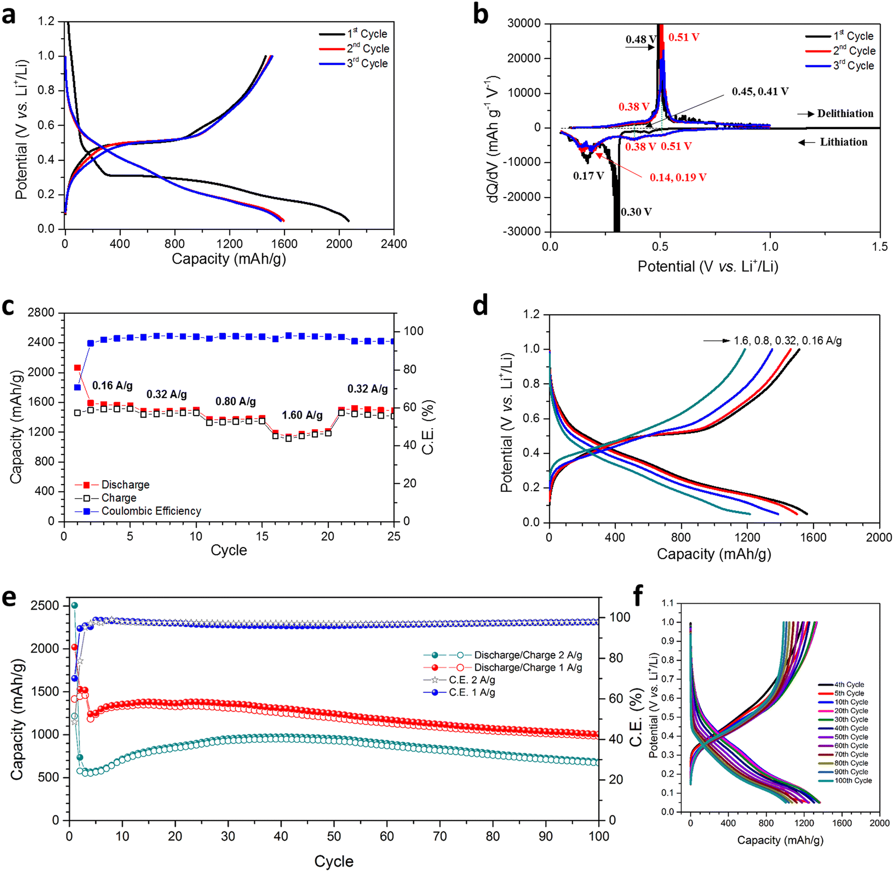 | ||
| Fig. 3 Electrochemical performance of the hierarchical NP Ge material in LIBs; (a) discharge/charge profiles at 160 mA g−1; (b) differential capacity plots against cell potential corresponding to (a); (c) rate performance at variable current densities; (d) corresponding discharge/charge potential profiles at the various current densities shown in (c); (e) cycling performance and corresponding coulombic efficiency at 1 A g−1 over 100 cycles (Nb. Cycles 1–3 were performed at 160 mA g−1) and 2 A g−1 for 100 cycles (Nb. Cycle 1 was performed at 160 mA g−1); and (f) the corresponding galvanostatic curves over selected cycles for the cell cycled at 1 A g−1 shown in (e). | ||
Differential capacity curves of cycles 1–3 were analysed in order to investigate the (de)lithiation phase-transfer mechanisms (Fig. 3(b)). The 1st lithiation exhibited two tiny peaks at 0.45 & 0.41 V and two obvious peaks at 0.30 & 0.17 V, implying multi-step activation and the alloying of NP Ge with Li, ultimately to form Li4.4Ge.14,15,34,47,48 Subsequent cycles exhibited two clear shifted reductive peaks at 0.51 & 0.38 V, the absence of a peak at 0.30 V and two peaks at 0.19 & 0.14 V. These differences are attributed to the overpotential, activation and SEI formation at the 1st lithiation.14,15,34,47,48 For the delithiation process, compared with cycle 1, cycles 2 & 3 show increased intensity at 0.38 V, although a peak cannot be incontrovertibly resolved. There is also a minor shift in potential for the main oxidative peak from 0.48 to 0.51 V, but the overlapping curves in cycles 2 & 3 indicate the absence of any irreversible reactions.15
The NP Ge electrode delivers an average discharge capacity of 1572.3, 1487.2, 1375.5, and 1182.6 mA h g−1 at a current density of 0.16, 0.32, 0.8, and 1.6 A g−1, respectively (Fig. 3(c)). The high capacity across current densities implies the vast majority of Ge is accessible in the electrode and that the diffusion of Li+ in the nanosized Ge ligaments is not inhibited; observations matched in other nanostructured Ge anodes.13,14,47 In this respect, the MIMP-fabricated dealloyed material exhibits a superior rate performance when compared to NP Ge (and Ag-embedded NP Ge) obtained from the eutectic alloys Al71.6Ge28.4 and Al80Ge15Ag5, respectively.33,34 From cycles 6–20, a high CE (>97.2%) was consistently registered as the current density was progressively increased and when the current density was reduced to 0.32 A g−1 at cycle 21, the discharge capacity quickly recovered to 1498.3 mA h g−1 with good reversibility. The incremental decrease in discharge capacity and CE in cycles 21–25 might be attributed to the likely larger Ge volume fluctuations associated with the higher discharge capacity than the value achievable at 1.6 A g−1. In this case, the SEI formed in the previous cycles is probably compromised/disrupted as a result. Indeed, previous studies have shown extensive disruption/formation of SEIs for Ge- and Si-based alloying materials associated with repetitive large scale electrode expansion and contraction.12–17,26,27,29,30,35 The observed behaviour is not surprising in view of the absence of any electrolyte additives (e.g. FEC and VC) in the cell systems and CEs can still register below 100% in some cases even with additives incorporated.12,26,27,29,30 Such additives have proven pivotal in facilitating the formation of a thin and flexible SEI with improved ionic conductivity, especially for large-volume expansion alloying electrode materials like Ge.18–20 The coherent and smooth potential curves at different current densities in Fig. 3(d) nevertheless suggest our NP Ge electrode is highly stable and exhibits low working potentials.
Encouraged by the excellent rate performance, our NP Ge electrodes were tested at high current densities (Fig. 3(e)). After activation at 0.16 A g−1 for the first cycle, one cell was cycled at 2.0 A g−1. The cell's discharge capacity was at a minimum over the 4th cycle (565.8 mA h g−1) and increased above 700 mA h g−1 after the 10th cycle, showing stable capacities at cycles 10–100 (where cycles 15–76 reached capacities >800 mA h g−1 with a maximum of 975.2 mA h g−1 over cycle 38). The 100th cycle still maintains (dis)charge capacities of 683.4 and 669.4 mA h g−1; almost twice the theoretical capacity of graphite. A second cell that was cycled at 1.0 A g−1 (after activation at 0.16 A g−1 for 3 cycles) yielded a discharge capacity of 1241.8 mA h g−1 at cycle 4, which subsequently increased over cycles 6–40 (producing 1300–1382.6 mA h g−1), which was potentially caused by the gradual activation during the cycling process. The capacity of this cell then decreases at a slow but steady rate, but nevertheless maintains a high discharge capacity of 1006.1 mA h g−1 by cycle 100. For both cells, the capacity increase in the first few tens of cycles immediately following the initial downturn may very likely originate from a gradual morphological-change-induced activation, which has been reported in a number of previous studies.12,14,26,27,30 Such structural changes in active materials have been revealed to contribute to the reduction of Li-ion diffusion resistance at high current densities in the anode.12,14,26,30 Analogous behaviour in our NP Ge cells is strongly indicated by the obvious decrease in over-potential in the galvanostatic curves that occur after cycle 5 in Fig. S14 (ESI†). The capacity fade and corresponding CE of <100% (95.9–98.8%) of both cells can likely be attributed to the non-ideal SEI as aforementioned.12–20,26,27,29,35 Then again, potential structural aggregation from cycle to cycle may also affect the cyclability (see the “Post-cycling Characterisation” section below).47 Nonetheless, the unoptimised results for the “bare” NP Ge systems shown in Fig. 3 provide a useful basis for the direct LIB performance evaluation of our NP Ge as compared to other untreated Ge electrodes. Subsequent inventive strategies such as surface coating (by carbon layers), nanostructuring as Ge–C frameworks, surface engineering by melamine coating, and/or incorporating electrolyte additives should further safeguard the NP Ge against pulverisation and promote the formation of a thin and flexible SEI to counter the sort of drift in capacity witnessed in Fig. 3(e).18–20,26,27,47,48
Galvanostatic potential data show that the discharge curves at 0.4–0.05 V are nearly parallel and that the charge curves at 0.1–0.6 V are almost superimposable for all cycles (Fig. 3(f)). These profiles suggest a uniformity in the phase transformations of the NP Ge structure. The decrease in the discharge and charge capacity at 1.0–0.4 V and 0.6–1.0 V, respectively are likely related to the loss of active sites at the surface of the constituent Ge nanoligaments.18–20,26,27 This is probably inevitable during the cycling-induced structural evolution and the continuous SEI (re)formation (Fig. 4(d)).18–20,26,27 By comparison and interestingly, ultra-conformal-Sb-coated NP Ge exhibits still lower stability at 1.0 A g−1 with untreated electrolyte, i.e. when FEC is absent; whereas NP Ge synthesised from H2-reduced GeO2 shows a rapid capacity decay even if FEC additives are incorporated in a cell (<150 mA h g−1 after 200 cycles).18 Another approach taken recently was to embed Ag nanoparticles into NP Ge, which improved electrical conductivity and cycling stability,34 but the capacities achieved by this approach are limited when compared to those achieved by the single-phase Ge produced by our MIMP/dealloying process. Our hierarchical NP Ge can maintain an impressive discharge capacity of 736.6 mA h g−1 after cycling at 1.0 A g−1 for 200 cycles (ESI,† Fig. S11a), therefore still accommodating almost twice as much charge as graphite by weight. It is worth also noting at this point that the cycling capacity of our hierarchical NP Ge product contrasts markedly with bulk commercial Ge itself (on the occasions that it has been tested in the literature). The latter (without additives or modification) typically shows a drastic capacity decrease below 400 mA h g−1 within ca. 15 cycles at 0.16 A g−1.33 The promising performance of the MIMP-derived Ge that can be achieved without additives or further modification can be largely attributed to the unique 3D, coral-like, NP structure, composed of both spherical- and lamella-type nanoligaments, which are the key microstructural features that engender multi-scale porosity.
 | ||
| Fig. 4 SEM images of NP Ge electrodes, (a), (b) before cycling; and (c), (d) after cycling tests at 1.0 A g−1 for 200 cycles. | ||
Post-cycling characterisation
To investigate the relationship between microstructure and cell performance further, ex situ SEM images of a NP Ge electrode were taken post-cycling (Fig. 4(c) and (d)). After 200 cycles at 1.0 A g−1, the cycled anode can be observed to have maintained its mechanical robustness with no obvious evidence of cracking, agglomeration or pulverisation. The morphology of the cycled NP Ge, however, varies considerably from the as-prepared NP Ge electrodes (Fig. 4(a) and (b)). The detectable but relatively minor coarsening can be likely attributed to the inevitable structural changes that occur during (de)lithiation (which are common for Ge or Si based alloying-type anodes) and the formation of the SEI.26,27,31 Notably, most of the particles post-cycling are within the range of 35–100 nm and the porosity is preserved with both meso- (>30 nm) and macro-pores (>100 nm – a few hundred nm) evident after 200 cycles at a relatively high current density of 1.0 A g−1.Further scrutiny of the electrode was undertaken using TEM techniques. High-angle annular dark-field scanning TEM (HAADF-STEM) imaging confirmed that the nanoporous features of the individual sub-micron to micron sized Ge particles were conserved after cycling (ESI,† Fig. S15a). However, imaging also indicates that the de-lithiated Ge particles form denser agglomerates (ESI,† Fig. S15b) when compared to the as-synthesised NP Ge particles (Fig. 2(h)). This is not an uncommon phenomenon for alloying-type anode materials.12,14,26 Medium- to high-resolution imaging (such as the image in Fig. S15b, ESI†) also reveals that the cycled NP Ge is less crystalline, with many particles exhibiting no clear lattice fringes in stark contrast to the as-synthesised material (Fig. 2(i)). Similar losses of crystallinity have been noted previously for porous Ge anodes and the transformation can be relatively rapid (for example, after only 10 cycles at 0.1 A g−1).14 The premise of lost crystallinity is reinforced by corresponding SAED patterns (ESI,† Fig. S15c) which present diffuse rings overlaid with very weak diffraction spots/powder rings. Findings from post-cycling PXD corroborated the observations from SAED with patterns yielding weak intensity peaks matching to Ge that had broadened considerably when compared with the same material before testing (ESI,† Fig. S16). These PXD results were useful, in fact, not only for confirming a loss of crystallinity and the formation of nanograins, but also in verifying that the reversibility of the Ge anode after many successive charge–discharge cycles. Irrespective of the cycling-induced changes in microstructure or crystallinity, Fig. 4 and Fig. S15b (ESI†) show that the Ge nanograins remain in close contact. This tight-knit microstructure provides a rationale for the appreciable electrical conductivity that exists post-cycling (ESI,† Fig. S13) and for the ability of the anode material to store lithium efficiently.14
The evident structural integrity of the anode post-cycling together with the cycling performance data themselves, are extremely encouraging considering the further improvements that might be made to trial cells (e.g. carbon coating, employing electrolyte additives and SEI engineering).11,18,19 It is very likely that the anode performance of MIMP-derived NP Ge, therefore, could be boosted further. Moreover, in terms of the material fabrication process itself, we take particular encouragement from previous results which indicate that vacuum dealloying can be applied to Mg2Si to yield nanoporous Si within 30 min.49 We will investigate combining MIMP reduction of oxides with modified vacuum de-alloying to achieve even faster and more energy-efficient delivery of NP Ge and related materials. Such methodological advances should present us with further variables to interrogate in the manufacture of high-specification LIB anodes.
Conclusions
In summary, plasma-phase processing paves the way for the deep reduction of GeO2 into Mg2Ge within 80 s using MIMP methods; an applied power of only 200 W is required. Subsequently, facile dealloying in air yields 3D hierarchical NP Ge with coral-like structures and bespoke multi-scale pore distributions. The unique porous design can be exploited in alloying electrodes where fast Li+ diffusion is promoted within a matrix of component nanoligaments. Further, the hierarchical porosity enhances the exposure of the anode to the electrolyte and accommodates the volume changes associated with (de)lithiation. The NP structure retains many of its multi-scale porous features after 200 cycles at 1 A g−1. These traits undoubtedly contribute to the high capacity, reliable stability and excellent rate capability that the NP Ge electrodes display. The processing method provides the starting point for the development of a route to the fabrication of NP Ge anode materials on larger scale; a manufacturing process that might be extended to other NP materials for LIBs and beyond. In the interim, further understanding of the structure-property relationships of the NP Ge material, the mechanism of charge–discharge and the optimisation of electrochemical cells are of immediate interest. Similarly, the fundamental underpinning physical chemistry and physics of the MIMP concept requires further scrutiny in order to broaden its applicability still further.Experimental
Synthesis of NP Ge
(1) GeO2reduction. The reduction-magnesiation of GeO2 was illustrated in Scheme 1. 1 mmol of GeO2 (Johnson Matthey) and 5.5 mmol of Mg powder (99.8%, 325 mesh, Alfa-Aesar) were mixed and transferred into a quartz tube. The sample preparation was performed within a N2-filled LABstar glovebox (mBRAUN) with water and oxygen levels controlled below 0.5 ppm. The quartz tube was then irradiated by MWs at 200 W under a static vacuum of 1.0 × 10⁻¹ mbar for 20 s, by using a modified single-mode MW cavity reactor (CEM Discovery, 2.45 GHz). The tube was left to cool down naturally, with the product retrieved and ground. The ground powders were then contained in another quartz tube and irradiated by MWs for a second cycle at 200 W under a static vacuum of 1.0 × 10⁻¹ mbar for 60 s. After the tube cooled naturally to room temperature, the product were retrieved.(2) Thermal dealloying and washing. The MW-irradiated powders were thermally dealloyed in air at 550 °C for 11 h in a box furnace (in the fumehood). As-obtained powder mixture was immersed with 1.0 M HCl aqueous solution for 30 min, and then washed with deionised water (3 times) and ethanol (3 times). After drying in an oven for 60 °C for 5 h, NP Ge powders were obtained, which were stored in the N2-filled glovebox for further experiments.
Materials characterisation
PANalytical X’pert Pro MPD diffractometer in Bragg–Brentano geometry (Cu Kα1 radiation λ = 1.5406 Å; accelerating voltage of 40 kV; emission current of 40 mA). Typically, PXD patterns were collected at room temperature over a 2θ range of 10–80° with a step size of 0.0334° for 15 min for phase-identification or from 10–110° (2θ) with a step size of 0.0167° for 2 h for structure refinement PXD measurements on post-galvanostatic cycled powders were performed in reflection geometry in airtight sample holders under a protective atmosphere of Ar. Scans were performed for 130 min over 10–90° (2θ) with a step size of 0.0167°.Scanning electron microscopy (SEM) and energy dispersive X-ray spectroscopy (EDS) were performed using either a Philips/FEI XL30 ESEM (beam voltage 20 kV, maximum magnification 20 k) equipped with an INCA X-Act detector (Oxford Instruments Analytical, UK), a Carl Zeiss Sigma Variable Pressure Analytical SEM or a Hitachi S-4100 microscope equipped with an INCA X-Act detector (Oxford Instruments Analytical, UK). Transmission electron microscopy (TEM) and selected area electron diffraction (SAED) of NP Ge powders were analyzed using a FEI, G2 F20X-Twin 200 kV, FEG microscope equipped with an energy-dispersive X-ray spectrometer (RTEM model SN9577, 134 eV) with measurements performed in the TEM mode (for bright-field imaging). The respective samples were retrieved from the glovebox in airtight containers and transferred rapidly to the microscopes.
High resolution Ge 3d X-ray photoelectron spectroscopy (XPS) was performed using a K-Alpha Photoelectron Spectrometer (monochromatic Al Kα, Thermo Scientific) under vacuum. Brunauer–Emmett–Teller (BET) analyses were performed on N2 adsorption–desorption isotherms measured at 77 K using a Micromeritics TriStar 3000 analyzer.
Transmission X-ray Microscopy (TXM) was performed at the Taiwan Light Source (TLS 01B1), National Synchrotron Radiation Center (NSRRC) in Hsinchu, Taiwan The Ge (111) toroidal focusing mirror provided monochromatic light with a photon energy of 8 keV. TXM 2D tomographic images were collected with a camera binning of 512 × 512 in pixels over a 60 s exposure time. 3D tomographic images and videos were reconstructed using Amira 3D image processing software. Quantitative analysis was performed using the SkyscanTM (CT analysis) software package (Bruker), following the transfer of the image set data and the definition of the sample volume (including open pores).
Electrochemical measurements
NP Ge powders were mixed with Super P carbon black (99+%, metal basis, Alfa Aesar) and sodium alginate (Sigma Aldrich) binder in a weight ratio of 70:15:15 in deionised water to form a homogeneous slurry. The slurry was coated onto a copper foil (10 microns in thickness). The prepared dry electrodes were used as working electrodes (16 mm in diameter); the final mass loading of active material was ca. 0.75–1.10 mg cm−2. A piece of glass-fiber D (GF/D, 20 mm in diameter, Whatman) filter paper was the separator. Li foil (99.9%, metal basis, 0.75 mm in thickness, Alfa Aesar) was manually polished and prepared into a clean Li disk (19 mm in diameter) as the counter electrode. The electrolyte was 1.0 M LiPF6 in ethylene carbonate/dimethyl carbonate (EC/DMC, 50/50, v/v; Sigma Aldrich). All half-cells were assembled using MIT split-able cells (inner diameter of 20 mm), in an Ar-filled glovebox with the H2O and O2 content below 0.5 ppm. (Dis)charging cycles were performed at room temperature using a galvanostatic programmable battery tester (Neware, CT – 4008, 5 V 10 mA) at different current densities with a cut-off potential range of 0.05–1.50 V.
Conflicts of interest
There are no conflicts to declare.Acknowledgements
DHG and ZF thank the University of Glasgow and the China Scholarship Council for the co-funding of a studentship for ZF. DHG thanks the Royal Society, RSC and EPSRC for associated funding under an International Exchange grant (IEC\R3\183040), an RSC COVID-19 Head of Department Grant (H20-118) and grant EP/N001982/1, respectively. W-R. L. gratefully acknowledges the Ministry of Science and Technology, Taiwan, for support under project grant no's MOST 110-2923-E-006 -011, 110-3116-F-011-002, 110-2622-E-033-009, 109-2911-I-033-502 and 108-E-033-MY3. The authors also acknowledge Mr Hsi-Nien Ho, Mr Cheng-Yi Lin and Ms Mei-Chun Lin (Chung Yuan Christian University) for assistance with XPS, SEM and BET measurements, respectively. Mr Youyi Sun is acknowledged for his assistance with EIS measurement. ZF thanks Mr Junying Huang and Dr Rasu Muruganantham (Chung Yuan Christian University) for helpful discussions re. battery testing. Mr Peter Chung and Mr James Gallagher (University of Glasgow) are acknowledged for assistance with SEM measurements.References
- R. Schmuch, R. Wagner, G. Hörpel, T. Placke and M. Winter, Nat. Energy, 2018, 3, 267–278 CrossRef CAS.
- W. L. Cai, Y. X. Yao, G. L. Zhu, C. Yan, L. L. Jiang, C. X. He, J. Q. Huang and Q. Zhang, Chem. Soc. Rev., 2020, 49, 3806–3833 RSC.
- R. Mo, F. Li, X. Tan, P. Xu, R. Tao, G. Shen, X. Lu, F. Liu, L. Shen, B. Xu, Q. Xiao, X. Wang, C. Wang, J. Li, G. Wang and Y. Lu, Nat. Commun., 2019, 10, 1474 CrossRef.
- T. Gao, Y. Han, D. Fraggedakis, S. Das, T. Zhou, C. N. Yeh, S. Xu, W. C. Chueh, J. Li and M. Z. Bazant, Joule, 2021, 5, 393–414 CrossRef CAS.
- Z. Fan, M. D. Cappelluti and D. H. Gregory, ACS Sustainable Chem. Eng., 2019, 7, 19686–19698 CrossRef CAS.
- W. Liu, H. S. Kim, S. Chen, Q. Jie, B. Lv, M. Yao, Z. Ren, C. P. Opeil, S. Wilson, C. W. Chu and Z. Ren, Proc. Natl. Acad. Sci. U. S. A., 2015, 112(11), 3269–3274 CrossRef CAS.
- J. J. Matin, J. Phys. Chem. Solids, 1972, 33(5), 1139–1148 CrossRef.
- J. Sun and D. J. Singh, Phys. Rev. Appl., 2016, 5(2), 024006 CrossRef.
- Z. Fan, G. Baranovas, H. A. Yu, R. Szczęsny, W. R. Liu and D. H. Gregory, Green Chem., 2021, 23, 6936–6944 RSC.
- Y. Zhang, N. Du, C. Xiao, S. Wu, Y. Chen, Y. Lin, J. Jiang, Y. He and D. Yang, RSC Adv., 2017, 7, 33837–33842 RSC.
- W. An, B. Gao, S. Mei, B. Xiang, J. Fu, L. Wang, Q. Zhang, P. K. Chu and K. Huo, Nat. Commun., 2019, 10, 1447 CrossRef.
- Q. Zhang, H. Chen, L. Luo, B. Zhao, H. Luo, X. Han, J. Wang, C. Wang, Y. Yang, T. Zhu and M. Liu, Energy Environ. Sci., 2018, 11, 669–681 RSC.
- D. Li, H. Wang, T. Zhou, W. Zhang, H. Liu and Z. Guo, Adv. Energy Mater., 2017, 7, 1700488 CrossRef.
- K. Mishra, X. C. Liu, F. S. Ke and X. D. Zhou, Composites, Part B, 2019, 163, 158–164 CrossRef CAS.
- F. S. Ke, K. Mishra, L. Jamison, X. X. Peng, S. G. Ma, L. Huang, S. G. Sun and X. D. Zhou, Chem. Commun., 2014, 50, 3713–3715 RSC.
- W. Li, X. Li, J. Yu, J. Liao, B. Zhao, L. Huang, A. Abdelhafiz, H. Zhang, J. H. Wang, Z. Guo and M. Liu, Nano Energy, 2019, 61, 594–603 CrossRef CAS.
- M. N. Obrovac and V. L. Chevrier, Chem. Rev., 2014, 114, 11444–11502 CrossRef CAS.
- B. Q. Xiong, X. Zhou, G. L. Xu, Y. Liu, L. Zhu, Y. Hu, S. Y. Shen, Y. H. Hong, S. C. Wan, X. C. Liu, X. Liu, S. Chen, L. Huang, S. G. Sun, K. Amine and F. S. Ke, Adv. Energy Mater., 2020, 10, 1903186 CrossRef CAS.
- B. Q. Xiong, X. Zhou, G. L. Xu, X. Liu, Y. Hu, Y. Liu, L. Zhu, C. G. Shi, Y. H. Hong, S. C. Wan, C. J. Sun, S. Chen, L. Huang, S. G. Sun, K. Amine and F. S. Ke, ACS Energy Lett., 2020, 5(11), 3490–3497 CrossRef CAS.
- C. Fang, J. Lau, D. Hubble, P. Khomein, E. A. Dailing, Y. Liu and G. Liu, Joule, 2021, 5, 415–428 CrossRef CAS.
- M. H. Park, K. Kim, J. Kim and J. Cho, Adv. Mater., 2010, 22, 415–418 CrossRef CAS PubMed.
- H. Kim, Y. Son, C. Park, J. Cho and H. C. Choi, Angew. Chem., Int. Ed., 2013, 52, 5997–6001 CrossRef CAS.
- M. H. Park, Y. Cho, K. Kim, J. Kim, M. Liu and J. Cho, Angew. Chem., Int. Ed., 2011, 50, 9647–9650 CrossRef CAS.
- D. J. Xue, S. Xin, Y. Yan, K. C. Jiang, Y. X. Yin, Y. G. Guo and L. J. Wan, J. Am. Chem. Soc., 2012, 134, 2512–2515 CrossRef CAS.
- E. A. Saverina, V. Sivasankaran, R. R. Kapaev, A. S. Galushko, V. P. Ananikov, M. P. Egorov, V. V. Jouikov, P. A. Troshin and M. A. Syroeshkin, Green Chem., 2020, 22, 359–367 RSC.
- K. Stokes, G. Flynn, H. Geaney, G. Bree and K. M. Ryan, Nano Lett., 2018, 18, 5569–5575 CrossRef CAS PubMed.
- K. Stokes, H. Geaney, G. Flynn, M. Sheehan, T. Kennedy and K. M. Ryan, ACS Nano, 2017, 11, 10088–10096 CrossRef CAS PubMed.
- J. Hwang, C. Jo, M. G. Kim, J. Chun, E. Lim, S. Kim, S. Jeong, Y. Kim and J. Lee, ACS Nano, 2015, 9, 5299–5309 CrossRef CAS.
- Y. An, Y. Tian, C. Wei, Y. Tao, B. Xi, S. Xiong, J. Feng and Y. Qian, Nano Today, 2021, 37, 101094 CrossRef CAS.
- T. Kennedy, E. Mullane, H. Geaney, M. Osiak, C. O’Dwyer and K. M. Ryan, Nano Lett., 2014, 14(2), 716–723 CrossRef CAS PubMed.
- Q. Yang, Z. Wang, W. Xi and G. He, Electrochem. Commun., 2019, 101, 68–72 CrossRef CAS.
- R. W. Mo, D. Rooney and K. N. Sun, iScience, 2018, 9, 521–531 CrossRef CAS PubMed.
- S. Liu, J. Feng, X. Bian, Y. Qian, J. Liu and H. Xu, Nano Energy, 2015, 13, 651–657 CrossRef CAS.
- Y. Yan, Y. Liu, Y. Zhang, C. Qin, Z. Bakenov and Z. Wang, J. Colloid Interface Sci., 2021, 592, 103–115 CrossRef CAS PubMed.
- Y. Yang, S. Liu, X. Bian, J. Feng, Y. L. An and C. Yuan, ACS Nano, 2018, 12(2900), 2908 Search PubMed.
- D. Kwon, J. Ryu, M. Shin, G. Song, D. Hong, K. S. Kim and S. Park, J. Power Sources, 2018, 374, 217–224 CrossRef CAS.
- D. Tang, H. Yu, J. Zhao, W. Liu, W. Zhang, S. Miao, Z. A. Qiao, J. Song and Z. Zhao, J. Colloid Interface Sci., 2020, 561, 494–500 CrossRef CAS PubMed.
- H. J. Kitchen, S. R. Vallance, J. L. Kennedy, N. Tapia-Ruiz, L. Carassiti, A. Harrison, A. G. Whittaker, T. D. Drysdale, S. W. Kingman and D. H. Gregory, Chem. Rev., 2014, 114, 1170–1206 CrossRef CAS.
- Z. Fan, H. N. Ho, R. Szczęsny, W. R. Liu and D. H. Gregory, CrystEngComm, 2022, 24, 5801–5809 RSC.
- S. R. M. Da Silva, G. K. Rolim, G. V. Soares, I. J. R. Baumvol, C. Krug, L. Miotti, F. L. Freire Jr, M. E. H. M. da Costa and C. Radtke, Appl. Phys. Lett., 2012, 100, 191907 CrossRef.
- L. Zhang, Q. Song and Z. Xu, J. Cleaner Prod., 2019, 207, 522–530 CrossRef.
- L. Rong, R. He, Z. Wang, J. Peng, X. Jin and G. Z. Chen, Electrochim. Acta, 2014, 147, 352–359 CrossRef CAS.
- Nonthermal plasma chemistry and physics, ed. J. Meichsner, M. Schmidt, R. Schneider and H. E. Wagner, CRC Press, Boca Raton, FL, 2013 Search PubMed.
- I. McCue, E. Benn, B. Gaskey and J. Erlebacher, Annu. Rev. Mater. Res., 2016, 46, 263–286 CrossRef CAS.
- X. Zhang, Z. Ju, Y. Zhu, K. J. Takeuchi, E. S. Takeuchi, A. C. Marschilok and G. Yu, Adv. Energy Mater., 2021, 11(2), 2000808 CrossRef CAS.
- K. S. Sing, Pure Appl. Chem., 1985, 57, 603–619 CrossRef CAS.
- S. Zhang, Y. Zheng, X. Huang, J. Hong, B. Cao, J. Hao, Q. Fan, T. Zhou and Z. Guo, Adv. Energy Mater., 2019, 9, 1900081 CrossRef.
- X. Liu, X. Y. Wu, B. Chang and K. X. Wang, Energy Storage Mater., 2020, 30, 146–169 CrossRef.
- Y. An, H. Fei, G. Zeng, L. Ci, S. Xiong, J. Feng and Y. Qian, ACS Nano, 2018, 12(5), 4993–5002 CrossRef CAS.
Footnote |
| † Electronic supplementary information (ESI) available: Documentation of supplementary experimental & analysis details plus supporting figures and tables; Supporting Video 1 (mkv) – 1st MW irradiation of Mg/GeO2 at 200 W for 20 s under a static vacuum (P = 1.0 × 10⁻¹ mbar), movie played at 1× speed with a frame rate of 60 f s−1; Supporting Video 2 (mkv) – 2nd MW irradiation of Mg/GeO2 at 200 W for 60 s under a static vacuum (P = 1.0 × 10⁻¹ mbar), movie played at 1× speed with a frame rate of 60 f s−1; Supporting Video 3 (mpg) – Constructed 3D TXM video of a particle of as-synthesised hierarchical nanoporous Ge; Supporting Video 4 (mkv) – MW irradiation of GeO2 powders at 200 W for 20 s under a static vacuum (P = 1.0 × 10⁻¹ mbar), movie played at 1× speed with a frame rate of 29 f s−1. See DOI: https://doi.org/10.1039/d2ma00847e |
| This journal is © The Royal Society of Chemistry 2022 |