
 Open Access Article
 This Open Access Article is licensed under a Creative Commons Attribution-Non Commercial 3.0 Unported Licence
Ion mobility and solvation complexes at liquid–solid interfaces in dilute, high concentration, and localized high concentration electrolytes†
Stefany
Angarita-Gomez
 and
Perla B.
Balbuena
*
and
Perla B.
Balbuena
*
Department of Chemical Engineering, Texas A&M University, College Station, TX 77843, USA. E-mail: balbuena@tamu.edu
First published on 30th June 2022
Abstract
The underlying mechanisms of the solvated lithium cation diffusion and deposition on the Li metal surface occurring at electrochemical interfaces are still not fully understood. In this work, density functional theory and a thermodynamic integration method implemented in constrained-ab initio molecular dynamics are used to calculate the free energy profile for the lithium cation transport pathway in the absence of an external field. The trajectory and evolution of the solvation complex surrounding the lithium cation, alongside the effect of salt concentration and diluent presence are studied in carbonate-based electrolytes including low concentration electrolytes (LCEs), high concentration electrolytes (HCEs), and localized high concentration electrolytes (LHCEs). Energy barriers for transport and desolvation are obtained with the thermodynamic integration method and discussed in relation to the solvation shell surrounding the Li-ion. In dilute electrolytes, the energy barriers for cation diffusion in the electrolyte phase are relatively low and the final deposition is guided mostly by solvent reduction. In HCEs, the high connectivity between the primary solvation complex and the rest of the electrolyte leads to a significant increase in the energy barriers for diffusion, and the ion can get trapped in the electrolyte slowing down the deposition, while the early development of SEI formation shows a thick and compact SEI structure built by anion decomposition. In the LHCE the diluent helps in reducing the barriers found in HCEs and breaking the high connectivity thus facilitating cation diffusion and the simultaneous SEI formation process.
Introduction
The lithium metal anode remains one promising alternative for better batteries due to its high theoretical capacity and low reduction potential.1 However, lithium metal has several challenges including extreme volume changes and uneven lithium deposition during battery cycling.2–7 In addition, lithium reactivity leads to the formation of dendrites and uncontrollable formation of a solid electrolyte interphase (SEI) resulting in capacity loss and safety concerns.8,9 Significant efforts have been made to overcome several of these challenges that will result in the practical use of lithium metal batteries.10,11 Several of these strategies involve the protection of the lithium metal anode, through the implementation of artificial SEIs,12–14 polymer or solid-state electrolytes, additives, ionic liquids, and engineering of electrolytes and their components.15–23 These modifications in the electrolyte components can lead to improvement in energy density, cost, and performance. In designing effective alternative liquid electrolyte solutions, a significant question remains: what is the connection between the microscopic structural and dynamic properties of the electrolyte solution and the observed cation deposition and initial stages of SEI morphologies and composition? Establishing this link would be a step ahead in a true electrolyte design for practical batteries.The key properties of the electrolyte and its components are defined by the solvation sheath formed around the lithium ions, because of its potential to impact the ion mobility as well as the interfacial behavior.24–26 Each of the components of the electrolyte including solvents, anions, and additives plays an important role in the ion mobility through their desolvation and electroreduction dynamic behavior. For example, the desolvation process of the Li+ cation on the surface is of great importance to understand the dendrite and SEI formation. This is because at the interface, the desolvation process is dictated by the electrolyte and its components control the interfacial structure that involves reaction kinetics and ion transport.27,28 Additionally, research has focused on correlating the asymmetry of the desolvation/solvation resistance of the Li cation with the suppression of dendrites.29
Furthermore, the structure and dynamics of the solvation complex also determine the structural and chemical properties of the nascent SEI due to the partial or total reduction caused by the electron transfer from the lithium metal surface to the solvation shell components.30 Thus, solvation shells are of great importance for understanding the transport and interfacial reaction mechanisms.31,32 An example of this is the application of molecular design based on the solvation ability of different solvents targeted to improve the performance of lithium metal batteries.33 However, the fundamental understanding of the mechanisms of diffusion and deposition is still incomplete due to the complex dynamic behavior of these solvation structures.
In previous work we investigated the effect of the chemistry of the solvents in the primary solvation sheath formed around lithium ions in dilute solutions, where we found a correlation between the reduction potential and the solvation structure and their effect on the diffusion and deposition pathway.34 High salt concentration electrolytes and the formation of localized high concentration regions by the addition of weakly interacting diluent species are some of the strategies shown to enhance the performance of lithium metal batteries. In this work, we characterize the effect of the primary (and sometimes secondary) solvation shell structure and the barriers and mechanisms of ion transport during its pathway from the “diffuse layer” to the interface with the Li anode and the associated events occurring during the desolvation process.
We analyze a series of electrolytes from a low concentration electrolyte (LCE or diluted electrolyte) to a high concentration electrolyte (HCE), as well as a localized high concentration electrolyte (LHCE). Multi-scale computational chemistry tools have proved to be useful for understanding the Li ion motion, from the atomic scale to the macroscopic level, providing additional insights into the use of computation to help evaluate such complex phenomena.35 In this study, we use density functional theory (DFT) and thermodynamic integration calculations implemented in constrained ab initio molecular dynamics (c-AIMD) to calculate the free energy profile of lithium ions with a full description of the barriers encountered by the cation due to solvation, diffusion, reaction, and deposition events. We focus on solutions of lithium bis(fluorosulfonyl)imide (LiFSI) in a dimethyl carbonate solvent (DMC) with or without a diluent and with various salt concentrations. Although this solvent choice limits our conclusions to electrolytes based on carbonate solvents which may not yield the best battery performances,36 the approach demonstrated here can be employed for any electrolyte formulation. The identification of the transport mechanisms is critical to provide new insights into the key steps that would determine cation deposition and reduction, or its incorporation into an SEI.
Computational and system details
In a previous study, electrolyte formulations (shown in Table S1, ESI†) that were proven effective in experimental work were modeled to understand the solvation structures and their interfacial reactivity.37 These electrolyte structures have been used as initial configurations in this work to study the interfacial behavior and the mechanisms of Li ion diffusion and deposition with their respective energy barriers during the cation desolvation pathway from the diffuse layer to the surface. The interfacial region used in this study (electrolyte and Li metal surface) can be characterized as the diffuse layer of the electrical double layer as the thickness of the electrolyte is less than ∼2 nm from the metal surface. All electrolytes are composed of LiFSI as the lithium salt, and DMC as the solvent, and for the LHCE bis(2,2,2-trifluoroethyl)ether (BTFE) is employed as the diluent. The LCE, HCE, and LHCE structures are placed on top of a 3-layer (100) Li metal slab. A single crystal layer of fixed helium atoms is placed at approximately 3 Å from the top of the simulation cell, to prevent interactions of the electrolyte with the bottom of the Li metal slab due to the periodic boundary conditions. Additionally, the bottom layer of the lithium metal slab is fixed to emulate bulk behavior. The simulation cell dimensions are 17.0 Å × 17.0 Å × 28.0 Å including the electrolyte on top of the lithium metal slab.The electrolyte and the lithium metal slab were optimized using DFT and a short Ab Initio Molecular Dynamics (AIMD) simulation of ∼1 ps was performed to relax all atoms in the new configuration. All calculations were performed using the Vienna ab Initio Simulation Package (VASP).38–40 The pseudopotentials used to describe the electron–ion interactions were the projector augmented wave (PAW)41,42 and for the exchange–correlation functional the Perdew–Burke–Ernzerhof generalized gradient approximation (GGA-PBE)43 was used. The k-point mesh used for the surface Brillouin zone integration was Monkhorst–Pack.44 A 2 × 2 × 1 k-point mesh was used for optimization and a 1 × 1 × 1 k-point mesh was used for AIMD and thermodynamic integration calculations. AIMD simulations were carried out in the canonical NVT ensemble at 330 K with a time step of 1 femtosecond. The Nose thermostat45,46 was used to keep the temperature constant with a damping parameter set to 0.5. The energy cut-off for the plane-wave basis expansion was chosen to be 400 eV and Gaussian smearing with a width of 0.05 eV was also utilized.
Thermodynamic integration calculations were performed through c-AIMD simulations in the blue moon ensemble as implemented in VASP. These calculations allow us to track the desolvation and deposition pathway of a lithium-ion from the diffuse layer to the lithium metal surface while understanding the energy barriers and the changes in the solvation complex that are part of the ion trajectory.47 Additional details about the thermodynamic integration method can be found in ref. 48–50. In this work, the reaction coordinate defined as the collective variable (ξ) is the motion of the lithium cation from an initial location (ξ1) towards a defined location (ξ2) in the lithium metal slab with a small step size of 0.0008 Å every femtosecond. Every step in this trajectory provides a free energy gradient (δF/Δξ), the value of the free energy gradient is obtained by averaging the dynamic trajectories over 100 fs, and the free energy ΔF is calculated as a path integral along an arbitrary path between ξ1 and ξ2.47
Results and discussion
LCEs and HCEs
Fig. 1 shows the initial structures for LCEs and HCEs where the salt concentrations are 1.21 M and 3.74 M LiFSI in DMC respectively. Both structures went through the optimization and short dynamic process described in the Computational and system details section. To understand the Li-ion mobility through the LCE diffuse layer and in the vicinity of the metal surface, a Li-ion (highlighted in green in Fig. 1a) is placed under a thermodynamic integration constraint to study its transport pathway. The primary solvation complex formed around the highlighted lithium-ion is shown in Fig. 1b; it is formed by two DMC molecules and one FSI anion. In contrast, in HCEs, the primary solvation complex shown in Fig. 1d is formed by two FSI− anions and two DMC solvent molecules. | ||
| Fig. 1 Initial structures of the low concentration electrolyte (1.21 M) and high concentration electrolyte (3.74 M) in DMC. (a) Initial structure for the low concentration electrolyte with initial solvation shell highlighted. (b) Close-up of the initial solvation shell in LCEs. (c) Initial structure for high concentration electrolyte with one solvation shell highlighted. (d) Close-up of initial solvation shell in HCEs. | ||
Images illustrating the Li-ion transport and deposition features in LCE solutions are shown in Fig. 2 alongside the free-energy profile and respective energy barriers. From the free energy profile shown in Fig. 2, we can observe that the lithium-ion moves with relatively low barriers during the whole path. Marks 1 through 7 highlight different events/changes in the solvation shell surrounding the lithium cation during its pathway (Fig. 2, bottom). Mark 1 is the initial solvation shell as previously described; the same molecules reconfigure around the Li-ion to find a more stable solvation shell with lower free energy in Mark 2 (relative change in free energy from Mark 2 to 1 is ΔF2-1 = −0.01 eV and energy barrier between the steps is Ea1′ = 0.08 eV). From Mark 2 to Mark 3 shown in Fig. 2, one of the initial DMC molecules left the solvation complex and the tetrahedral structure around the cation is preserved by the FSI anion coordinating with two O atoms. Although the same solvation shell structure remains for Mark 4, the energy increases from F3 = 0.13 eV to F4 = 0.20 eV due to the energetic cost of diffusion of the cation along with its solvation shell. In Mark 5 a new DMC joins the solvation complex causing one of the previous DMC molecules to leave the shell on Mark 6; this indicates the easier rearrangement of solvent molecules while the same anions remain tightly linked to the cation in the solvation shell. Additionally, from Mark 2 to Mark 6 the solvation shell rotates so the anion is directed toward the lithium metal surface. This is because the electron transfer from the surface exerts a force that first attracts the species with higher electron affinity, that is the anion. Finally, on Mark 7 all solvent molecules have left the solvation complex, the anion gets partially reduced by defluorination and the fluorine atom joins the Li cation to form LiF, a characteristic component of the SEI layer. A summary and energy barrier description of all steps evaluated for LCEs can be found in Fig. S1 (ESI†). The free energy gradient per step (i.e., the forces) in the thermodynamic integration calculation oscillates around zero because the forces are zero at a free energy minimum and also at the transition state (maximum in free energy). These free energy gradients are shown as a blue trajectory in Fig. 2, 3, 5, and 6.
 | ||
| Fig. 2 Free-energy profile (red) and free energy gradient (blue) as a function of the collective variable ξ for lithium cation diffusion and deposition in LCE, 1.21 M LiFSI in DMC. Marks 1 through 7 in the free energy pathway are solvation shells illustrated at the bottom. The Li ion migrates from the initial location in the electrolyte (in 1) to come in contact with the surface atoms (in 7). | ||
 | ||
| Fig. 3 Free-energy profile (red) and free energy gradient (blue) of lithium cation diffusion and deposition in high concentration electrolyte 3.74 M LiFSI in DMC located on top of the surface. Marks 1 through 3 in the energy pathway are solvation shells found around the lithium cation shown at the bottom. Color code as in Fig. 1. | ||
Fig. 3 displays the mechanism of diffusion and deposition of the Li-ion in HCEs and the free-energy profile along the pathway. The energy pathway looks very different than in LCEs mainly because of the magnitude of the energy barriers. This is because in HCE solutions a cation does not belong to only one solvation shell but is part of a highly interconnected 3-D network. Thus, in HCE solutions, the cation must overcome extremely high barriers in the desolvation and deposition pathway. The initial solvation complex shown in Fig. 3 Mark 1 is formed from 2 DMC molecules and 2 FSI anions, this solvation complex does not change, from Mark 1 to Mark 2 only the vertical diffusion of the solvation complex is observed with a relatively low energy barrier. However, from Mark 2 to Mark 3 the energy barrier is Ea2′ = 5.61 eV indicating an event that is energetically taxing or impossible due to the magnitude. The high energy barrier is in agreement with experimentally found low cation mobility in HCEs,51 and they correspond to the binding energies of the Li cation in the 3D structure generated in HCE solutions.52–54 The main reason for this behavior is highlighted in Mark 3 where the primary solvation complex is trapped in a highly connected network where the targeted solvation shell is linked to a secondary or even a tertiary solvation complex. In such a network, the anions from one solvation shell coordinate with other Li cations and their solvation shells. The cation not only has to diffuse out from the primary solvation shell but from a larger network that hinders ionic transport through the electrolyte. Therefore, the electrolyte layer closer to the surface, usually dominated by anions, gets reduced first and may open a channel for cation flow. The SEI formation in the HCE is considerably large, most of the surface lithium is consumed, combining with products from the decomposition of electrolyte molecules. A summary of energy barriers and their description is given in Fig. S2 (ESI†). Dragging such a complex to the surface requires more electron transfer from the slab. Therefore in step 3, fresh lithium was added and the cation was able to arrive at the surface with much lower barriers (steps 3 to 4), the results are shown in Fig. S3 in the ESI.† Thus, in the free energy pathway (red line) shown in Fig. 3, it is observed that after step 3, the cation trapped in the electrolyte structure is able to return to a normal flat pathway (between 3 and 4).
LHCEs
The initial configuration of a cell containing an LHCE is shown in Fig. 4a where the Li-ions have different local environments. Shells 1 to 4 shown in Fig. 4 illustrate different possible primary solvation complexes surrounding a lithium ion in the LHCE phase. The solvation shells may look like the LCE (Shell 1) or extremely high concentration electrolyte (Shell 3) and just high concentration electrolyte (Shell 2 and Shell 4) with and without diluent respectively. The Li ions in all these different solvation shells were studied to understand the effect of the primary solvation complex, as well as the different components of the LHCE in the cation desolvation and deposition pathway.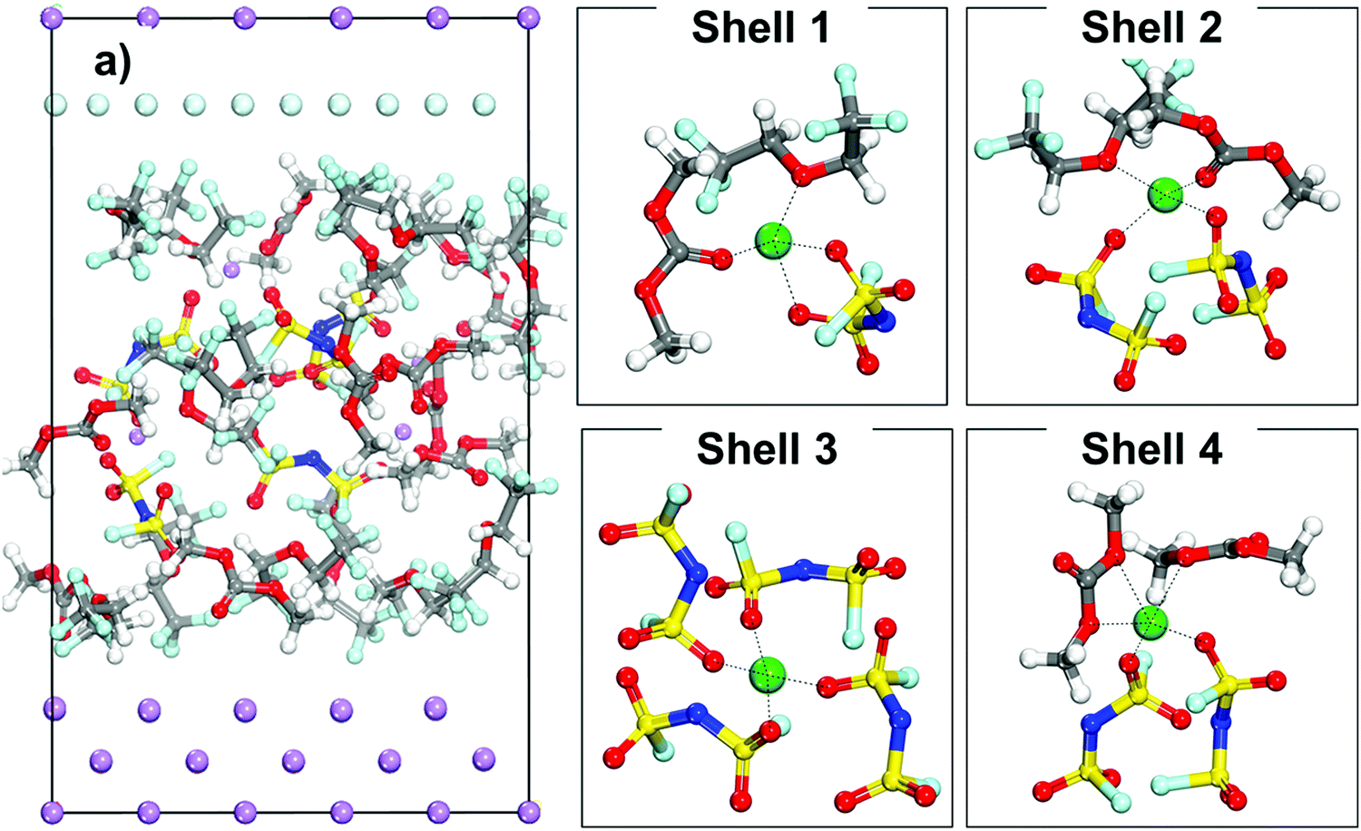 | ||
| Fig. 4 (a) Initial configuration of a cell with a localized high concentration electrolyte (LHCE) (1.27 M LiFSI). Shells 1 through 4 showcase examples of different initial solvation shells that a lithium cation encounters in this electrolyte. | ||
Fig. 5 displays the free energy profile of a lithium cation in an LHCE that is initially surrounded by a solvation complex Shell 1 (shown in Fig. 4). The initial solvation complex in Fig. 5, Mark 1 is formed by one component of each species and includes a solvent molecule, an anion, and a diluent molecule. When the cation is under the thermodynamic integration constraint and approaches the lithium metal surface the first significant change in the solvation complex (Mark 2, Fig. 5) occurs by lowering of the free energy to find an even more stable configuration by substituting the diluent molecule in the primary solvation complex with a LiF molecule. Such a LiF molecule was formed from a fluorine atom from the reduction of a nearby anion bonded to a Li atom.
 | ||
| Fig. 5 Free-energy profile (red) and free energy gradient (blue) of lithium cation diffusion and deposition in the localized high concentration electrolyte (top picture). Marks 1 through 5 in the energy pathway are the solvation shells found around the lithium cation that starts in Shell 1 (Fig. 4) and are shown at the bottom. Color code as in Fig. 1. | ||
Fig. 5 shows a relatively flat free energy profile. However, there are some significant barriers. The largest energy barrier takes place between steps 2 and 3: Ea2′ = 0.37 eV, corresponding to the diffusion of the solvation complex formed in Mark 2 in which the anion coordinates with two O atoms to the lithium-ion. The following barrier between Mark 3 and 4 is Ea3′ = 0.15 eV and marks the addition of another fluorine atom to the solvation complex, as well as the diffusion and rotation of the anion toward the lithium metal surface. The end of the diffusion pathway of the cation starting in Shell 1 is a relatively easier step with no energy barrier and lowers the free energy ΔF5-4 = −0.07 (Mark 5) mainly because the anion motion towards the surface is driven by the anion being reduced and decomposed by the Li metal. Additionally, after the anion in the solvation complex is part of the nascent SEI, our cation of interest ends up being part of a LiF SEI nanocluster on top of the other SEI components being created by the reduction of other electrolyte molecules.
The main learnings from Shell 1 in LHCEs are that the diluent being a weakly interacting species is not expected to be in the primary solvation complex surrounding the lithium ion. Instead, the diluent does not affect the original Li salt–solvent coordination and is usually located on the secondary solvation shell.55 LHCEs exhibit the advantages of HCEs in the local environment, but also other advantages including low viscosity, and lowering of the cost.56 On the other hand, we observe that the cation is driven towards the surface accompanied by a changing solvation shell, where SEI components become more and more involved as the cation becomes closer to the surface.
Fig. 6 shows a lithium cation in Shell 4 in the same LHCE. This solvation complex is formed by 2 anions and 2 solvent molecules and its structure resembles the primary solvation complex found in HCEs, as shown in Fig. 3. However, the main difference is the absence of the 3D interconnected network present in HCE solutions. Although the cations shown in Fig. 5 and 6 are placed in the same LHCE and the same cell structure, the free energy profile of the diffusion and deposition pathway presented different energy barriers and transport mechanisms indicating the effect of the primary solvation complex.
 | ||
| Fig. 6 Free-energy profile (red) and free energy gradient (blue) of lithium cation diffusion and deposition in a localized high concentration electrolyte (top picture). Marks 1 through 7 in the energy pathway are the solvation shells found around the lithium cation that starts in Shell 4 (Fig. 4) and are shown at the bottom. Color code as in Fig. 1. | ||
At the beginning of the ion transport pathway (from Mark 1 to Mark 4 in Fig. 6), the changes to the primary solvation complex include only the solvent molecules. For example, from Mark 1 to Mark 2 one of the initial DMC molecules leaves the solvation complex, and later, on Mark 3 the other initial DMC molecule swaps places with another solvent molecule. All these changes occur relatively easy with low barriers (∼< 0.15 eV). In contrast, the largest barrier was found from Mark 3 to Mark 4 at Ea3′ = 0.58 eV and corresponds to the diffusion of the solvation complex of all molecules found in Mark 3. Additionally, the events in Mark 4 allow us to understand the role of the diluent on the secondary solvation shell. By zooming out of the primary solvation shell we can observe that it is surrounded by the diluent molecules and their role is to lower the energy barriers for the cation to dissociate from the anion during the diffusion and deposition process. Although this initial primary solvation shell resembles the one in an HCE, the LHCE diluent in the secondary solvation shell breaks up the high connection between the primary and secondary solvation shells present in HCEs. Thus, in contrast with the HCE environment, the diluent isolates the anion–cation complex, which can finally be disrupted.
The diluent molecules allow the solvation complex to approach the surface and from Mark 4 to Mark 5 in Fig. 6, the solvated ion moves with Ea4′ = 0.45 eV, where the solvent molecule has left the shell possibly temporarily displaced by the diluent, defining an alternative slightly higher local concentration environment. Toward the end of the pathway (from Mark 5 to Mark 7) the diluent molecules move out of the diffusion pathway facilitating ion diffusion.57 At the end (from Mark 6 to Mark 7), the anions get reduced by the cleavage of the S–N bond and the Li-ion became part of the nascent SEI. A summary and energy barrier description of LHCE shell 1 and shell 4 are shown in Fig. S4 and S5 (ESI†) respectively.
The results of Shell 2 (Fig. 4) are not discussed because this shell behaves similarly to Shell 1. Finally, the results of Shell 3 shown in Fig. 4 are presented in Fig. 7. These shells have a higher local concentration including more anions per solvation shell than any of the previous cases, although the tetrahedral coordination for the Li cation is maintained. A good representation of the typical evolution behavior of this shell is shown in Fig. 7, in which the lithium-ion gets trapped in the electrolyte and a small SEI nanocluster starts to form via successive anion reduction, that eventually and after reaching a critical mass can be deposited on top of the Li metal surface.
 | ||
| Fig. 7 Solvation shells found around the lithium cation that starts in Shell 3 (Fig. 4). Color code as in Fig. 1. | ||
Discussion
Fig. 8 summarizes representative energy barriers found in the LCE, HCE, and LHCE in this work, allowing the direct comparison and visualization of the effect of salt concentration on the magnitudes of the energy barriers experienced by the solvated cation during its transport through the diffuse layer and deposition pathway. The highest barriers in LCEs correspond to motion steps involving the cation along with the solvation shell, such as the transition from step 2 to 3, which is a rearrangement of the solvation shell where one solvent molecule is substituted by the multiple coordination of the anion molecule indicating that the rate determining step (rds) is the ion transport in the electrolyte. In LCEs, the lowest barrier is the deposition of the cation and it is driven by the partial reduction of the anion. In HCEs, the strong 3D network of interconnected solvation shells dominated by anions makes the cation motion extremely slow, becoming the rds. The surface effect reduces the anion and opens up a channel for cation migration. The LHCE solutions may resemble both behaviors, depending on the specific solvation shell. In Shell 1 (Fig. 8), the largest barrier corresponds to vehicular diffusion of a shell where the cation is surrounded by solvent, anion, and one F atom subproduct of decomposition of another anion near the surface. These shell components induce stronger cation–shell interactions than in the LCE case. In Shell 4 (Fig. 8), the largest barrier corresponds to the vehicular motion of a cation surrounded by 2 anions +1 solvent, which becomes closer to HCE behavior. However, the solvent substitution by the diluent reduces the barrier of the next step. | ||
| Fig. 8 Comparison of energy barriers for cation motion in all electrolytes in this study. The LiFSI salt concentration varies from 1.21 M in the LCE to 3.74 M in the HCE and 1.27 M in the LHCE solutions. Here, the horizontal axis indicates the location of the barrier (between the n and n + 1 steps). | ||
The average error in the calculated free energy gradient (δF/Δξ) is 0.016 eV Å−1 for LCEs, using the block average method. Details of the error calculation are provided in the ESI.† To use the block average method, we run 2000 steps at a reduced step size of 8 × 10⁻⁶ in every relevant structure. For LCEs this means running an additional 14![[thin space (1/6-em)]](https://www.rsc.org/images/entities/char_2009.gif) 000 steps, i.e., a high computational cost. However, an approximation to the error can be made based on the actual force fluctuations, since the step size of the simulations presented in this study is relatively small (8 × 10⁻⁴) and the estimated error (based on the force fluctuations) remains small for all the studied systems. The approximated errors are 0.127 eV Å−1 for the HCE and 0.017 eV Å−1 for the LHCE.
000 steps, i.e., a high computational cost. However, an approximation to the error can be made based on the actual force fluctuations, since the step size of the simulations presented in this study is relatively small (8 × 10⁻⁴) and the estimated error (based on the force fluctuations) remains small for all the studied systems. The approximated errors are 0.127 eV Å−1 for the HCE and 0.017 eV Å−1 for the LHCE.
An interesting question relates to the rate-determining step for cation deposition. In previous work34 based on LCEs we found that depending on the electrolyte chemistry, mass transport or electrochemical kinetics may be the limiting step. This is because the solvent34 and anion (shown in this work) have electron affinities that compete with that of the cation. If the electrolyte components are reduced first, the cation can continue to electrodeposition (in the earlier stages of SEI formation) with mass transport being the rds. If the SEI is already formed, the cation may become part of the SEI or get electrodeposited. In addition, once the SEI forms, the surface properties (ability to transfer electrons) change, and this again affects the competition between electrolyte components and cation for the surface electrons. In summary, there is no fixed rule that decides the rds, and which mechanism is dominant would be dependent on the electrolyte/surface case.
The selected studied configurations are representative of each type of electrolyte. We note that in the LCE, the anion is not always present in the cation solvation shell. However, the LCE free energy profile reported here (in the presence of the anion) is similar to the earlier report for carbonates,34 where the anion was not present. For HCEs, the solvation shells may be populated by an even higher number of anions, but the results shown here illustrate the most important effect that comes from the insertion of the solvation shell in a 3D highly interconnected network. For LHCEs we showed four different configurations, and as the results indicate the barriers are highly dependent on them. Therefore, the results in Fig. 8 provide a good idea about the variation of the magnitude of these barriers according to the electrolyte composition. In summary, in LCEs the interfacial cation motion is driven by relatively low barriers of a similar order of magnitude. In HCEs, breaking the highly connected barrier would result in huge barriers that eventually would be overcome at the cost of slowing down the transport. This is because, near the surface, the high electron affinity of the anion will make it degrade forming an SEI, and liberating the cation. In LHCEs, the richer spectra of configurations would make a more diverse spectrum of barriers, and this work shows the positive effect of the diluent in reducing these barriers.
As shown here, a variety of factors affect ion transport. And this is precisely the value of the theoretical work, that allows identifying the possible bottlenecks that impede ion transport in a well-defined environment. Experiments such as impedance measurements that provide resistances to ion transport are another possibility for comparison to experiments. But this would require further analysis of the experimental results that we have not attempted yet, but it could be valuable.
With respect to the electric field effect, in our previous work58 we estimated barriers for cation electrodeposition under an electric field for a Li ion solvated by an anion and DME molecules on Cu surfaces. We examined several cases of varying salt concentration, in some respects similar to this work. Likewise, solvent decomposition reactions and their activation energies were found to become more favorable with lower activation energies and more exothermic reaction energies as the electric field increased.59 From the results of the previous studies, the electric field would direct the ion towards the anode surface (as the constrained AIMD results showed in this work), and as the electric field increases, the barriers would decrease and the deposition reaction would become more exothermic.
Conclusions
This study provides the dynamic evolution of the solvation complex defined as the molecules in the immediate vicinity of the Li cation as it approaches the interfacial region, and especially the role of the surrounding environment in defining barriers for ion transport and reaction. The desolvation and deposition pathways observed in different electrolytes and the identification of their relevant barriers allow us to understand the limiting steps during the ion transport process near the surface, and to characterize the cation deposition mechanism in the early stages of SEI formation.It is found that in LCE solutions with carbonate solvents, the cation transport pathway is relatively easy with low barriers determined by changes of the solvation complex, usually by solvent rearrangement. Near the surface, the solvated ion complex rotation driven by the high electron affinity of the anion, leads to the partial reduction of the anion and eventual deposition of the Li cation on the surface or formed SEI. In contrast, in HCEs the highly connected primary solvation complex with secondary and tertiary solvation shells leads to a large increase in the energy barriers during the ion transport pathway, which results in a slowdown of the ion flow, and a rapid and usually large SEI formation dominated by anion products.
A different scenario defined by the role of the local environment, as well as that of the diluent, is found in LHCE solutions. We investigated this point by examining several possible initial solvation complexes. For the LHCE in this study, the diluent molecules are found in the secondary solvation complex surrounding the primary solvation shell. However, the diluent also has the possibility of breaking the interaction between the high primary shell and surrounding shells characteristic of HCEs, and lowering the desolvation energy barriers. The diluent molecule is not regularly found in the primary solvation complex, but occasionally it can facilitate ion transport by a temporary substitution of a solvent molecule in that shell. The diluent molecule in LHCEs can also facilitate SEI formation by anion decomposition. This is observed when the local environment is highly concentrated, the ion gets trapped in the electrolyte phase and SEI nanoclusters were observed to grow next to the surface, but still in the liquid phase. Depending on the surrounding environment, this nanocluster may increase in size with the incorporation of similar fragments or become surrounded by a different SEI (for example organic, from solvent decomposition). In summary, this work highlights the role of the electrolyte in the interfacial ion transport and initial stages of SEI formation showcasing low and moderate barriers for ion transport in LCEs and LHCEs, whereas additional barriers slowing down transport are found in HCEs. The methodology used in this study would require large amounts of computational power to run longer time frames or larger simulation cells. The results in this study allow us to see the behavior of the cation while approaching the metal slab surface during the early stages of SEI formation. However, a fully-formed, stable SEI might affect the cation deposition mechanism and introduce other energy barriers. Future work will address these issues.
Conflicts of interest
There are no conflicts of interest to declare.Acknowledgements
This work was supported by the Assistant Secretary for Energy Efficiency and Renewable Energy, Office of Vehicle Technologies of the US Department of Energy through the Advanced Battery Materials Research (BMR) Program (Battery500 Consortium phase 2) under DOE contract no. DE-AC05-76RL01830 from the Pacific Northwest National Laboratory (PNNL). Computational resources from the Texas A&M University High Performance Research Computing are gratefully acknowledged.References
- B. Liu, J.-G. Zhang and W. Xu, Advancing Lithium Metal Batteries, Joule, 2018, 2, 833–845 CrossRef CAS.
- C. Fang, X. Wang and Y. S. Meng, Key Issues Hindering a Practical Lithium-Metal Anode, Trends Chem., 2019, 1, 152–158 CrossRef CAS.
- J. B. Goodenough and Y. Kim, Challenges for Rechargeable Li Batteries, Chem. Mater., 2010, 22, 587–603 CrossRef CAS.
- X. Chen, T. Hou, K. A. Persson and Q. Zhang, Combining theory and experiment in lithium–sulfur batteries: Current progress and future perspectives, Mater. Today, 2019, 22, 142–158 CrossRef CAS.
- K. Fu, Y. Gong, G. T. Hitz, D. W. McOwen, Y. Li, S. Xu, Y. Wen, L. Zhang, C. Wang, G. Pastel, J. Dai, B. Liu, H. Xie, Y. Yao, E. D. Wachsman and L. Hu, Three-dimensional bilayer garnet solid electrolyte based high energy density lithium metal–sulfur batteries, Energy Environ. Sci., 2017, 10, 1568–1575 RSC.
- J. Lai, Y. Xing, N. Chen, L. Li, F. Wu and R. Chen, Electrolytes for Rechargeable Lithium–Air Batteries, Angew. Chem., Int. Ed., 2020, 59, 2974–2997 CrossRef CAS PubMed.
- D. Lin, Y. Liu and Y. Cui, Reviving the lithium metal anode for high-energy batteries, Nat. Nanotechnol., 2017, 12, 194 CrossRef CAS PubMed.
- L. Fan, H. L. Zhuang, W. Zhang, Y. Fu, Z. Liao and Y. Lu, Stable Lithium Electrodeposition at Ultra-High Current Densities Enabled by 3D PMF/Li Composite Anode, Adv. Energy Mater., 2018, 8, 1703360 CrossRef.
- W. Xu, J. Wang, F. Ding, X. Chen, E. Nasybulin, Y. Zhang and J.-G. Zhang, Lithium metal anodes for rechargeable batteries, Energy Environ. Sci., 2014, 7, 513–537 RSC.
- X.-B. Cheng, R. Zhang, C.-Z. Zhao and Q. Zhang, Toward Safe Lithium Metal Anode in Rechargeable Batteries: A Review, Chem. Rev., 2017, 117, 10403–10473 CrossRef CAS PubMed.
- J.-G. Zhang, W. Xu, J. Xiao, X. Cao and J. Liu, Lithium Metal Anodes with Nonaqueous Electrolytes, Chem. Rev., 2020, 120, 13312–13348 CrossRef CAS PubMed.
- G. Zheng, S. W. Lee, Z. Liang, H.-W. Lee, K. Yan, H. Yao, H. Wang, W. Li, S. Chu and Y. Cui, Interconnected hollow carbon nanospheres for stable lithium metal anodes, Nat. Nanotechnol., 2014, 9, 618–623 CrossRef CAS PubMed.
- D. Aurbach, E. Zinigrad, H. Teller and P. Dan, Factors which limit the cycle life of rechargeable lithium (metal) batteries, J. Electrochem. Soc., 2000, 147, 1274–1279 CrossRef CAS.
- Y. Liu, D. Lin, P. Y. Yuen, K. Liu, J. Xie, R. H. Dauskardt and Y. Cui, An Artificial Solid Electrolyte Interphase with High Li-Ion Conductivity, Mechanical Strength, and Flexibility for Stable Lithium Metal Anodes, Adv. Mater., 2017, 29, 1605531 CrossRef PubMed.
- L. E. Camacho-Forero, T. W. Smith, S. Bertolini and P. B. Balbuena, Reactivity at the Lithium–Metal Anode Surface of Lithium–Sulfur Batteries, J. Phys. Chem. C, 2015, 119, 26828–26839 CrossRef CAS.
- W.-J. Zhang, A review of the electrochemical performance of alloy anodes for lithium-ion batteries, J. Power Sources, 2011, 196, 13–24 CrossRef CAS.
- V. Etacheri, O. Haik, Y. Goffer, G. A. Roberts, I. C. Stefan, R. Fasching and D. Aurbach, Effect of Fluoroethylene Carbonate (FEC) on the Performance and Surface Chemistry of Si-Nanowire Li-Ion Battery Anodes, Langmuir, 2012, 28, 965–976 CrossRef CAS PubMed.
- P. Verma, P. Maire and P. Novák, A review of the features and analyses of the solid electrolyte interphase in Li-ion batteries, Electrochim. Acta, 2010, 55, 6332–6341 CrossRef CAS.
- J. M. Martinez de la Hoz, K. Leung and P. B. Balbuena, Reduction Mechanisms of Ethylene Carbonate on Si Anodes of Lithium-Ion Batteries: Effects of Degree of Lithiation and Nature of Exposed Surface, ACS Appl. Mater. Interfaces, 2013, 5, 13457–13465 CrossRef CAS PubMed.
- P. Ganesh, P. R. C. Kent and D.-E. Jiang, Solid–Electrolyte Interphase Formation and Electrolyte Reduction at Li-Ion Battery Graphite Anodes: Insights from First-Principles Molecular Dynamics, J. Phys. Chem. C, 2012, 116, 24476–24481 CrossRef CAS.
- N.-W. Li, Y. Shi, Y.-X. Yin, X.-X. Zeng, J.-Y. Li, C.-J. Li, L.-J. Wan, R. Wen and Y.-G. Guo, A Flexible Solid Electrolyte Interphase Layer for Long-Life Lithium Metal Anodes, Angew. Chem., Int. Ed., 2018, 57, 1505–1509 CrossRef CAS PubMed.
- R. Bouchet, S. Maria, R. Meziane, A. Aboulaich, L. Lienafa, J.-P. Bonnet, T. N. T. Phan, D. Bertin, D. Gigmes, D. Devaux, R. Denoyel and M. Armand, Single-ion BAB triblock copolymers as highly efficient electrolytes for lithium-metal batteries, Nat. Mater., 2013, 12, 452–457 CrossRef CAS PubMed.
- S. Jiao, J. Zheng, Q. Li, X. Li, M. H. Engelhard, R. Cao, J.-G. Zhang and W. Xu, Behavior of Lithium Metal Anodes under Various Capacity Utilization and High Current Density in Lithium Metal Batteries, Joule, 2018, 2, 110–124 CrossRef CAS.
- K. Xu, Electrolytes and Interphases in Li-Ion Batteries and Beyond, Chem. Rev., 2014, 114, 11503–11618 CrossRef CAS PubMed.
- X.-Q. Zhang, X. Chen, X.-B. Cheng, B.-Q. Li, X. Shen, C. Yan, J.-Q. Huang and Q. Zhang, Highly Stable Lithium Metal Batteries Enabled by Regulating the Solvation of Lithium Ions in Nonaqueous Electrolytes, Angew. Chem., Int. Ed., 2018, 57, 5301–5305 CrossRef CAS PubMed.
- J. Zheng, J. A. Lochala, A. Kwok, Z. D. Deng and J. Xiao, Research Progress towards Understanding the Unique Interfaces between Concentrated Electrolytes and Electrodes for Energy Storage Applications, Adv. Sci., 2017, 4, 1700032 CrossRef PubMed.
- A. Baskin and D. Prendergast, Ion Solvation Engineering: How to Manipulate the Multiplicity of the Coordination Environment of Multivalent Ions, J. Phys. Chem. Lett., 2020, 11, 9336–9343 CrossRef CAS PubMed.
- R. Attias, M. Salama, B. Hirsch, Y. Goffer and D. Aurbach, Anode-Electrolyte Interfaces in Secondary Magnesium Batteries, Joule, 2019, 3, 27–52 CrossRef CAS.
- N. Tanibata, R. Morimoto, K. Nishikawa, H. Takeda and M. Nakayama, Asymmetry in the Solvation–Desolvation Resistance for Li Metal Batteries, Anal. Chem., 2020, 92, 3499–3502 CrossRef CAS PubMed.
- K. Xu, “Charge-Transfer” Process at Graphite/Electrolyte Interface and the Solvation Sheath Structure of Li[sup +] in Nonaqueous Electrolytes, J. Electrochem. Soc., 2007, 154, A162 CrossRef CAS.
- G. Agarwal, H. A. Doan and R. S. Assary, Molecular Structure and Electron Affinity of Metal-Solvent Complexes: Insights from Density Functional Theory Simulations, J. Electrochem. Soc., 2020, 167, 100545 CrossRef CAS.
- A. Baskin, J. W. Lawson and D. Prendergast, Anion-Assisted Delivery of Multivalent Cations to Inert Electrodes, J. Phys. Chem. Lett., 2021, 12, 4347–4356 CrossRef CAS PubMed.
- Y. Chen, Z. Yu, P. Rudnicki, H. Gong, Z. Huang, S. C. Kim, J.-C. Lai, X. Kong, J. Qin, Y. Cui and Z. Bao, Steric Effect Tuned Ion Solvation Enabling Stable Cycling of High-Voltage Lithium Metal Battery, J. Am. Chem. Soc., 2021, 143, 18703–18713 CrossRef CAS PubMed.
- S. Angarita-Gomez and P. B. Balbuena, Solvation vs. surface charge transfer: an interfacial chemistry game drives cation motion, Chem. Commun., 2021, 57, 6189–6192 RSC.
- S. Shi, J. Gao, Y. Liu, Y. Zhao, Q. Wu, W. Ju, C. Ouyang and R. Xiao, Multi-scale computation methods: Their applications in lithium-ion battery research and development, Chin. Phys. B, 2016, 25, 018212 CrossRef.
- Z. Yu, H. Wang, X. Kong, W. Huang, Y. Tsao, D. G. Mackanic, K. Wang, X. Wang, W. Huang, S. Choudhury, Y. Zheng, C. V. Amanchukwu, S. T. Hung, Y. Ma, E. G. Lomeli, J. Qin, Y. Cui and Z. Bao, Molecular design for electrolyte solvents enabling energy-dense and long-cycling lithium metal batteries, Nat. Energy, 2020, 5, 526–533 CrossRef CAS.
- S. Perez Beltran, X. Cao, J.-G. Zhang and P. B. Balbuena, Localized High Concentration Electrolytes for High Voltage Lithium–Metal Batteries: Correlation between the Electrolyte Composition and Its Reductive/Oxidative Stability, Chem. Mater., 2020, 32, 5973–5984 CrossRef CAS.
- G. Kresse and J. Furthmuller, Efficiency of ab-initio total energy calculations for metals and semiconductors using a plane-wave basis set, Comput. Mater. Sci., 1996, 6, 15–50 CrossRef CAS.
- G. Kresse and J. Hafner, Ab initio molecular dynamics for liquid metals, Phys. Rev. B: Condens. Matter Mater. Phys., 1993, 47, 558 CrossRef CAS PubMed.
- G. Kresse and J. Hafner, Ab initio molecular-dynamics simulation of the liquid-metal--amorphous-semiconductor transition in germanium, Phys. Rev. B: Condens. Matter Mater. Phys., 1994, 49, 14251–14269 CrossRef CAS PubMed.
- P. E. Blöchl, Projector augmented-wave method, Phys. Rev. B: Condens. Matter Mater. Phys., 1994, 50, 17953 CrossRef PubMed.
- G. Kresse and D. Joubert, From ultrasoft pseudopotentials to the projector augmented-wave method, Phys. Rev. B: Condens. Matter Mater. Phys., 1999, 59, 1758–1775 CrossRef CAS.
- J. P. Perdew, K. Burke and M. Ernzerhof, Generalized Gradient Approximation Made Simple, Phys. Rev. Lett., 1996, 77, 3865–3868 CrossRef CAS PubMed.
- H. J. Monkhorst and J. D. Pack, Special points for Brillouin-zone integrations, Phys. Rev. B: Solid State, 1976, 13, 5188–5192 CrossRef.
- S. Nosé, A unified formulation of the constant temperature molecular dynamics methods, J. Chem. Phys., 1984, 81, 511–519 CrossRef.
- W. G. Hoover, Canonical dynamics: Equilibrium phase-space distributions, Phys. Rev. A: At., Mol., Opt. Phys., 1985, 31, 1695–1697 CrossRef PubMed.
- T. Bucko, Ab initiocalculations of free-energy reaction barriers, J. Phys.: Condens. Matter, 2008, 20, 064211 CrossRef CAS PubMed.
- Y. Komeiji, Implementation of the blue moon ensemble method, Chem-Bio Inf. J., 2007, 7, 12–23 CAS.
- G. Ciccotti and M. Ferrario, Blue Moon Approach to Rare Events, Mol. Simul., 2004, 30, 787–793 CrossRef CAS.
- T. Cheng, H. Xiao and W. A. Goddard, Free-Energy Barriers and Reaction Mechanisms for the Electrochemical Reduction of CO on the Cu(100) Surface, Including Multiple Layers of Explicit Solvent at pH 0, J. Phys. Chem. Lett., 2015, 6, 4767–4773 CrossRef CAS PubMed.
- Y. Yamada and A. Yamada, Review-Superconcentrated Electrolytes for Lithium Batteries, J. Electrochem. Soc., 2015, 162, A2406–A2423 CrossRef CAS.
- S.-D. Han, O. Borodin, D. M. Seo, Z.-B. Zhou and W. A. Henderson, Electrolyte Solvation and Ionic Association, J. Electrochem. Soc., 2014, 161, A2042–A2053 CrossRef CAS.
- S. C. Kim, X. Kong, R. A. Vilá, W. Huang, Y. Chen, D. T. Boyle, Z. Yu, H. Wang, Z. Bao, J. Qin and Y. Cui, Potentiometric Measurement to Probe Solvation Energy and Its Correlation to Lithium Battery Cyclability, J. Am. Chem. Soc., 2021, 143, 10301–10308 CrossRef CAS PubMed.
- T. Doi, H. Oae and M. Inaba, How is the concentration determined for rapid lithium ion transfer in highly concentrated electrolyte solutions?, Electrochem. Sci. Adv., 2022, 2, e2100058 Search PubMed.
- S. Chen, J. Zheng, D. Mei, K. S. Han, M. H. Engelhard, W. Zhao, W. Xu, J. Liu and J.-G. Zhang, High-Voltage Lithium-Metal Batteries Enabled by Localized High-Concentration Electrolytes, Adv. Mater., 2018, 30, 1706102 CrossRef PubMed.
- X. Cao, H. Jia, W. Xu and J.-G. Zhang, Review—Localized High-Concentration Electrolytes for Lithium Batteries, J. Electrochem. Soc., 2021, 168, 010522 CrossRef CAS.
- S. Perez Beltran, X. Cao, J.-G. Zhang, P. Z. El-Khoury and P. B. Balbuena, Influence of diluent concentration in localized high concentration electrolytes: elucidation of hidden diluent-Li+ interactions and Li+ transport mechanism, J. Mater. Chem. A, 2021, 9, 17459–17473 RSC.
- R. C. Longo, L. E. Camacho-Forero and P. B. Balbuena, Charge-mediated cation deposition on metallic surfaces, J. Mater. Chem. A, 2019, 7, 8527–8539 RSC.
- L. E. Camacho-Forero and P. B. Balbuena, Effects of charged interfaces on electrolyte decomposition at the lithium metal anode, J. Power Sources, 2020, 472, 228449 CrossRef CAS.
Footnote |
| † Electronic supplementary information (ESI) available: Images and description of intermediate steps for each energy profile are discussed. See DOI: https://doi.org/10.1039/d2ma00541g |
| This journal is © The Royal Society of Chemistry 2022 |