DOI:
10.1039/D1MA00767J
(Paper)
Mater. Adv., 2022,
3, 474-483
Microporous MOF as nanogen facilitating diffusion-coupled charge transfer near the percolation threshold in a polyaniline pseudo-supercapacitor
Received
26th August 2021
, Accepted 31st October 2021
First published on 17th November 2021
Abstract
Several approaches have recently been investigated with the aim of enhancing the specific capacitance of polyaniline (PANI). We herein report a novel pathway to boost the specific capacitance of PANI, which is highly tunable and versatile, based on wet chemistry techniques. In this approach, utilization of a specific metal–organic framework (MOF), UiO-66-NH2, as a nanopore generator (Nanogen) is demonstrated. This systematic study demonstrates a tight interplay between the enhanced electrolyte accessibility to the PANI chains, through the incorporation of MOF nanogens, and the optimal relative amount of the conductive PANI, necessary to attain a charge percolation threshold in the binary system (MOF@PANI). Satisfying the charge percolation while maintaining porosity is necessary to arrive at a maximized specific capacitance of the PANI as the active phase. The enhancement in the specific capacitance of the PANI was fully exploited through a systematic investigation that helped to pinpoint the saddle point at which the two orthogonal properties, namely porosity (electrolyte diffusivity) and charge mobility (PANI inter-chain electronic conductivity) can be fine-tuned via controlling the materials composition. Of the different compositions investigated, the composite containing 23 wt% PANI of the total weight, doped with MOF nanogens, resulted in an enhanced specific capacitance of 872 F g−1 for the PANI, in comparison to only 469 F g−1 for the pristine PANI investigated under identical conditions.
Introduction
The distinctive high surface area, presence of chemically functionalized nanocages, and uniform pore systems are all common attributes of the large family of microporous solids. Among these, zeolites, metal–organic frameworks (MOFs),1 and porous organic polymers (POPs),2 as well as covalent-organic frameworks (COFs)3 have attracted considerable interest due to their proven uses in several applications. Implementation of microporous solids in water treatment,4,5 catalysis,6–8 gas sorption and separation,9,10 and battery technology,11 among others, are largely facilitated due to their intrinsic properties; namely the dimensionality and functionality of their cages and/or pores.
Conductive polymers have emerged as a novel class of materials that can bridge the gap between metals, with their superior electronic conductivity, and organic matter, as well as their ease of synthesis and functionalization.12 PANI is arguably one of the most explored conductive polymers.13–15 Due to its enhanced electronic conductivity and redox behavior, it was recently investigated for its potential as a pseudosupercapacitor material.16–19 Recently, the construction of microporous materials on conductive supports, including graphene and multi-walled carbon nanotubes (MWCNTs), has provided an efficient pathway to merge the microporosity and electrical conductivity of such composites.20–23
In recent studies, MOF–PANI hybrid materials were recently explored with demonstrated performance as electrode materials for several electrochemical applications. Recent examples have included the utilization of MOF@Se@PANI composites in batteries,24 MOF@PANI for the hydrogen evolution reaction (HER) in electrocatalysis,25 Ni–MOF/PANI-derived materials for electrochemical sensors,26 as well as Ni–MOF–PANI nanosheets used in supercapacitors.27 The aforementioned applications were accessed through the synthesis of various MOF–PANI composites, each tailored to a specific application by judicial choice of the different components in the composite.
In other previous reports, it was demonstrated that the presence of several types of MOFs,28 including UiO-6629 and ZIF-67,30,31 resulted in enhanced electrochemical performance of MOF–PANI hybrids. However, we opted here to explore the potential of the amine-functionalized MOF UiO-66-NH2 due to its excellent chemical stability and presence of ionizable amine groups that can facilitate ion mobility within the material. A recent study also demonstrated the efficient confinement of PANI chains within the pores of UiO-66-NH2, with a positive impact on the stability of the PANI chains observed upon extended cycling.32 Attempts were also successfully made to link the observed enhancement to the intrinsic microporosity of the MOFs and the electrical conductivity of the PANI.33 However, a deeper understanding of the underlying mechanism for this observed synergy is still lacking.
In this report, a systematic investigation was conducted, by varying the UiO-66-NH2 to PANI composition in a well-controlled in situ PANI polymerization setup, in order to decipher the relative significance that the intrinsic properties of the two components of the composite have on the overall observed performance of the materials as an electrode material for supercapacitor applications. PANI utilization as an electrode material in supercapacitors stems from its high electrical conductivity (∼101 S cm−1)34 and pronounced electrochemical activity due to its ability to undergo doping/dedoping states. Although PANI has a theoretical specific capacitance of 964 F g−1, calculated assuming a potential window of 1.1 V,35 without taking into consideration capacitance from the electrical double layer, this is greatly affected by the surface area of the PANI. However, under practical conditions, such maximal specific capacitance is difficult to attain. Specifically, care must be taken when conducting electrochemical measurements on PANI, by cycling within the potential range that can result in reversible oxidation from leucoemeraldine (L) to emeraldine (E), avoiding irreversible damage to the PANI when measurements were extended to the fully oxidized state, pernigraniline (P).35 A large number of reports have demonstrated enhancement in the specific capacitance of PANI through different methodologies, where in the vast majority the target was to enhance the surface-to-volume ratio of PANI molecular wires.36,37 This is of interest when designing a supercapacitor material in order to enhance the surface charge density and therefore increase the specific capacitance of the same material. Earlier attempts in that direction targeted the formation of PANI nanowires,38 their deposition on flat supports,39 increasing their surface roughness and decreasing the particle size,40etc.
Results and discussion
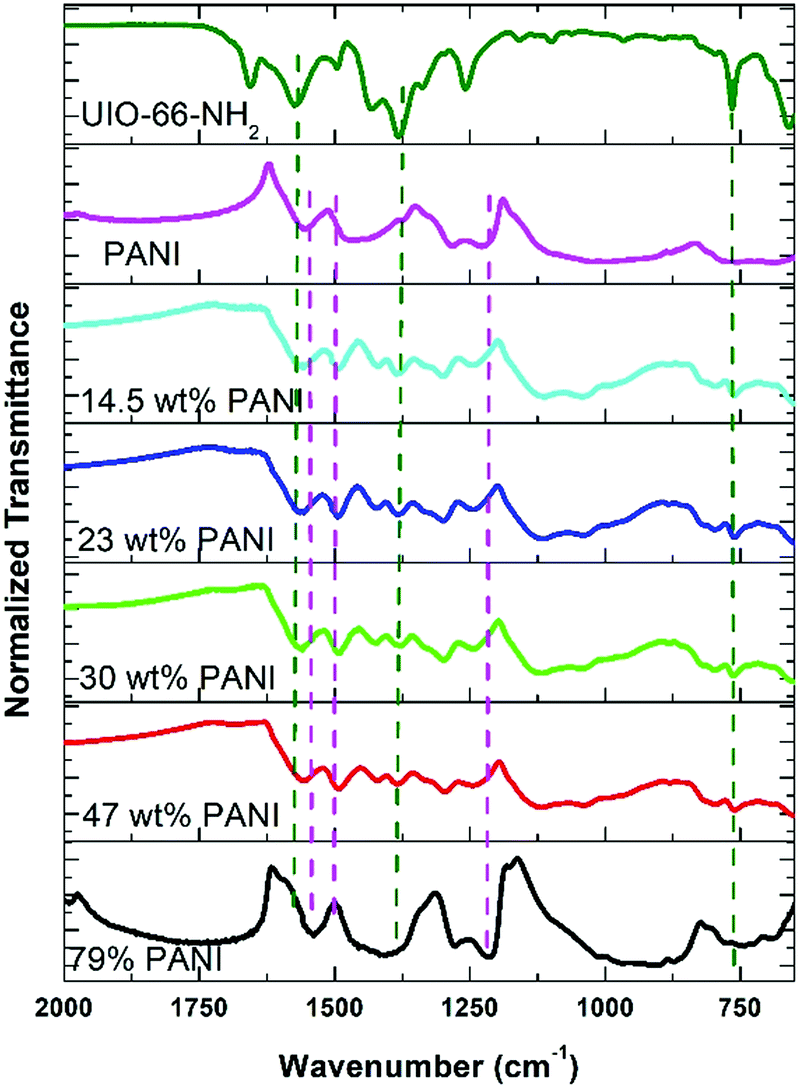
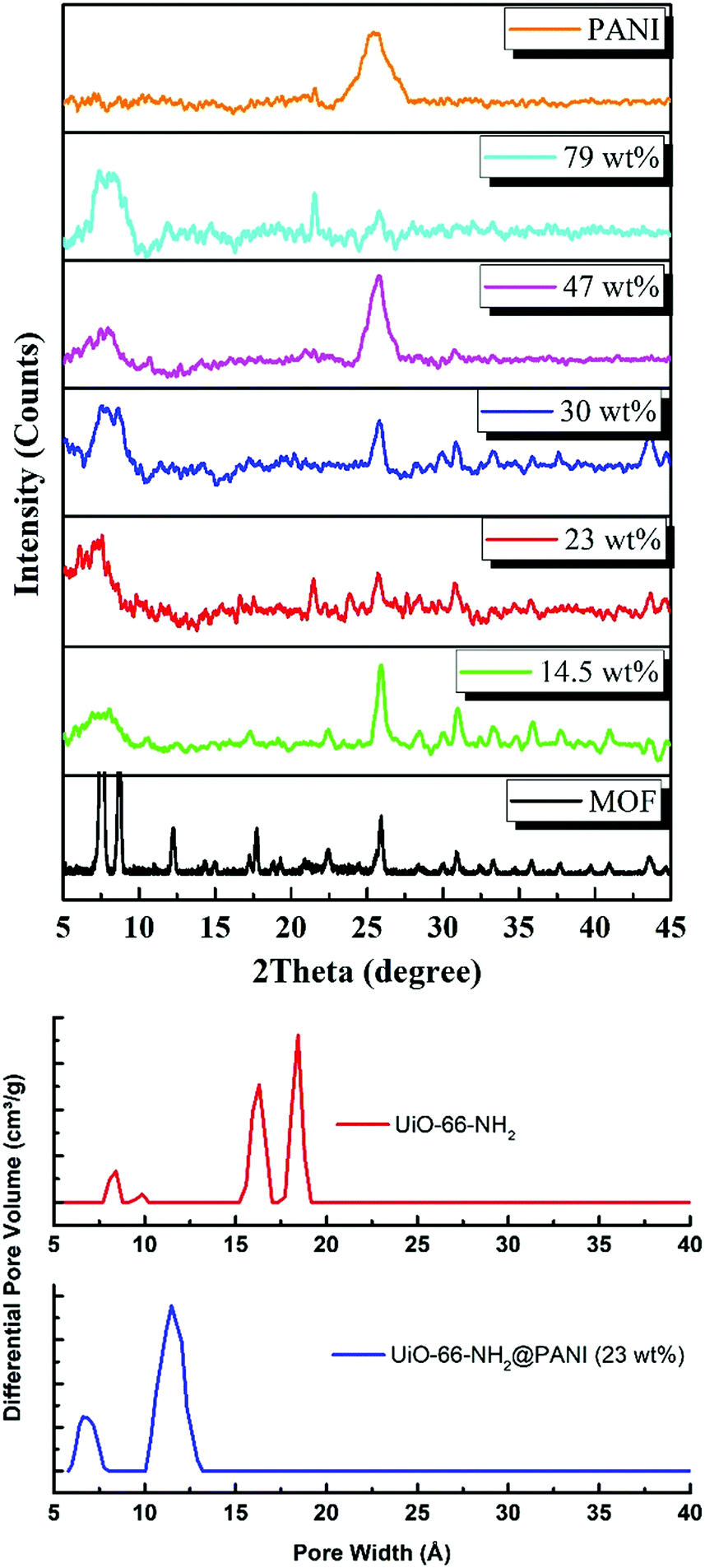
In the approach presented herein, we opted to utilize a specific MOF to be incorporated as a filler within the matrix of PANI. More specifically, the enhanced microporosity, chemical stability, and high surface area of the Zr-based MOF (UiO-66-NH2)41 were key to its selection for this study. In this design, the incorporation of homogeneously dispersed nanocrystallites of the MOF within the matrix of PANI was targeted to provide ion-conducting nano-channels imbedded in-between the PANI polymer chains (Scheme 1). By providing such action to facilitate ion migration from the electrolyte to reach deeper into the PANI chains and their subsequent electrosorption onto the polymer chains, the MOF can effectively be regarded as a filler for generating nanocavities, which we refer to here as nanogens. This is in analogy to the well-established concept of utilizing porogens in the fabrication of porous polymer membranes, where mostly nanoparticles of soluble salts are physically blended within a viscous solution of the polymer, which can subsequently then be leached out from the casted membrane to leave behind a uniform array of pores.42–44 In this design, we envisioned that two orthogonal properties, namely the microporosity of the MOF filler with its fairly low electrical conductivity, and the low porosity of the PANI with its high electrical conductivity, need to be optimized in order to realize the full potential of the nanogens. Therefore, to capture the saddle point at which the favorable impact of the MOF on the overall MOF–PANI composite is maximized, a systematic investigation was conducted to probe the optimal MOF composition that can result in enhanced ion mobility within the matrix of the composite, yet without drastically decreasing the electrical conductivity of the overall composite. As the former is a viable target to enhance diffusivity of electrolyte species to reach the PANI–electrolyte interface, the latter is the essential element to maintain, in order to retain good electronic properties for the supercapacitor electrode. The synthesis we report here is highly controllable, allowing for the isolation of different compositions with increasing concentration of the nanogen filler. This strategy is especially suited for the systematic study of the global variance in the MOF–PANI composition needed to result in the optimized performance of the PANI as a pseudosupercapacitor. The PANI wt% in the end product can readily be tuned by controlling the ratio between the MOF filler and the aniline–ammonium persulfate mixture at the beginning of the reaction. Suspending the MOF nanocrystals into the PANI precursor solution while maintaining mechanical stirring resulted in the nucleated growth and deposition of the PANI chains onto the MOF crystals, resulting in a textured morphology of the obtained composite, as shown in the scanning electron microscopy (SEM) images in Fig. 1. Five different MOF@PANI compositions were synthesized, namely those containing 14.5 wt%, 23 wt%, 30 wt%, 47 wt%, and 79 wt% of PANI within the composite. To further characterize the samples prepared, Fourier-transform infrared (FTIR) spectra of PANI, UiO-66-NH2, and the different MOF@PANI compositions were recorded and are shown in Fig. 2. The major characteristic peaks of the UiO-66-NH2 include the Zr–O stretching at 765 cm−1, the carboxylate C–O symmetric and asymmetric stretching (1380 cm−1 and 1574 cm−1, respectively), as well as the C![[double bond, length as m-dash]](https://www.rsc.org/images/entities/char_e001.gif) C stretching observed at 1432 cm−1.45 The FTIR spectrum of PANI exhibits characteristic peaks at 1560, 1472 and 1297 cm−1. The peaks at 1560 and 1478 cm−1 can be assigned to the CC stretching of quinoid and benzenoid rings, respectively, while the band observed at 1283 cm−1 can be assigned to C–N stretching vibrations.46 Interestingly, the composites with lower PANI wt% demonstrate mostly the characteristic peaks of the MOF, with a decrease in the intensity of the MOF peaks observed upon an increase in the mass% of the PANI in the composite, until the MOF peaks become barely noticeable in the spectrum of the composite containing 79 wt% PANI. Furthermore, Fig. 3 shows the powder X-ray diffraction (PXRD) patterns of PANI, UiO-66-NH2, and the different MOF@PANI composites. The PANI diffraction pattern features a broad peak at 2θ = 25.4° signifying its highly doped emeraldine salt form.47 All of the MOF@PANI composites show the characteristic peaks of UiO-66-NH2, whereas as the PANI content increases, the characteristic peaks for the MOF become less visible. The changes in the pore size distribution histograms, Fig. 3b, demonstrate that the pore systems centered at ∼1.6 and 1.8 nm in the UiO-66-NH2 MOF are lost in the PANI@MOF composite, indicating a buildup of the PANI molecules within the cages of the MOF.
C stretching observed at 1432 cm−1.45 The FTIR spectrum of PANI exhibits characteristic peaks at 1560, 1472 and 1297 cm−1. The peaks at 1560 and 1478 cm−1 can be assigned to the CC stretching of quinoid and benzenoid rings, respectively, while the band observed at 1283 cm−1 can be assigned to C–N stretching vibrations.46 Interestingly, the composites with lower PANI wt% demonstrate mostly the characteristic peaks of the MOF, with a decrease in the intensity of the MOF peaks observed upon an increase in the mass% of the PANI in the composite, until the MOF peaks become barely noticeable in the spectrum of the composite containing 79 wt% PANI. Furthermore, Fig. 3 shows the powder X-ray diffraction (PXRD) patterns of PANI, UiO-66-NH2, and the different MOF@PANI composites. The PANI diffraction pattern features a broad peak at 2θ = 25.4° signifying its highly doped emeraldine salt form.47 All of the MOF@PANI composites show the characteristic peaks of UiO-66-NH2, whereas as the PANI content increases, the characteristic peaks for the MOF become less visible. The changes in the pore size distribution histograms, Fig. 3b, demonstrate that the pore systems centered at ∼1.6 and 1.8 nm in the UiO-66-NH2 MOF are lost in the PANI@MOF composite, indicating a buildup of the PANI molecules within the cages of the MOF.
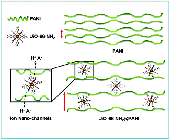 |
| | Scheme 1 Schematic representation of the effect of inclusion of the UiO-66-NH2 MOF to facilitate ion diffusion through the nanopores of the MOF acting as a nanogen between the PANI chains. | |
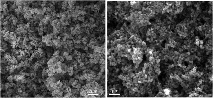 |
| | Fig. 1 SEM images of the UiO-66-NH2 MOF (left) and the MOF@PANI (right), showing the textured morphology of the MOF–PANI composite. | |
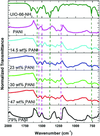 |
| | Fig. 2 FTIR spectra of the UiO-66-NH2, PANI, and the composites with different PANI compositions. The dotted lines show the characteristic peaks of UiO-66-NH2 (green) and PANI (violet). | |
 |
| | Fig. 3 (Top) XRD patterns of MOF, PANI, and their reported composites (the wt% refers to that of the PANI), and (below) the pore size distribution histogram of the MOF and PANI@MOF 23 wt% composite. | |
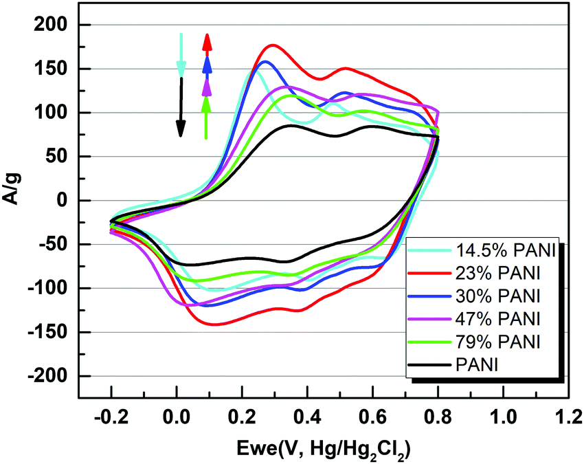
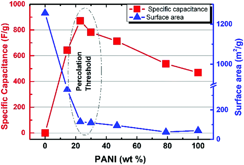
Overall, five different samples of varying PANI–MOF compositions were tested for their electrochemical response via cyclic voltammetry (CV) measurements, in addition to those of the pristine MOF and PANI, using a three electrode system in 1 M H2SO4 aqueous electrolyte, Fig. 4, to determine the specific capacitance of the PANI in each sample. The CV scans in Fig. 4 clearly demonstrate the initial enhancement in the PANI pseudo electrochemical capacitance upon introducing the MOF into the composite, where the composite with 79 wt% PANI demonstrated slightly enhanced specific capacitance (537 F g−1) compared to that of the pristine PANI (469 F g−1). Increasing the MOF content resulted in a further enhancement in the PANI specific capacitance, where the sample containing 47 wt% PANI showed a specific capacitance of 718 F g−1, increasing in the sample containing 30 wt% PANI (782 F g−1), and further increasing in the sample containing 23 wt% (872 F g−1), before dropping in the sample containing 14.5 wt% PANI (643 F g−1). Moreover, noticeable changes in the peak shape, comparing the sample of pristine PANI to those containing the MOF fillers, were noticeable. The CV scans of the samples containing the nanogens demonstrated a more pronounced diffusion-controlled redox process of the PANI, evident in the well-resolved double hump shape of the CV scans. This observation points towards facilitated ion diffusion from the electrolyte to reach deeper into the PANI chains in the presence of the nanogens. Plots of the specific capacitance and surface area of the obtained solids versus the PANI wt% are shown in Fig. 5. It is clear from this data that the increase in surface area as a result of the increased MOF wt% is accompanied by an increase in the specific capacitance of the PANI, reaching an inflection point beyond the sample containing 23 wt% PANI. Interestingly, this behavior is in agreement with a previous investigation on the charge percolation threshold of a graphene–MOF composite system, where a sudden increase in the overall electrical conductivity of the composite was attained at ∼30 wt% conductive filler composition.23 This charge percolation threshold, identified previously for a different MOF–graphene system seems to hold true in this case as well, taking into consideration the different nature of the conductive element in the composite.
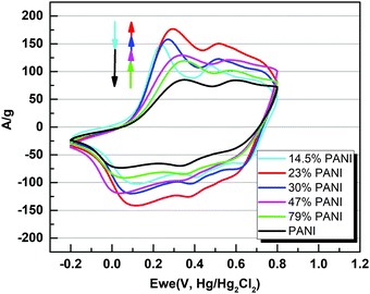 |
| | Fig. 4 Cyclic voltammetry (CV) plots of PANI and its composites deposited on glassy carbon electrodes at a scan rate of 10 mV s−1 in 1 M H2SO4. | |
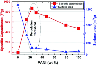 |
| | Fig. 5 Composite surface area and specific capacitance of PANI dependence on the wt% of the PANI in the MOF@PANI, showing the highest attained specific capacitance at an optimal composition of 23 wt% PANI. | |
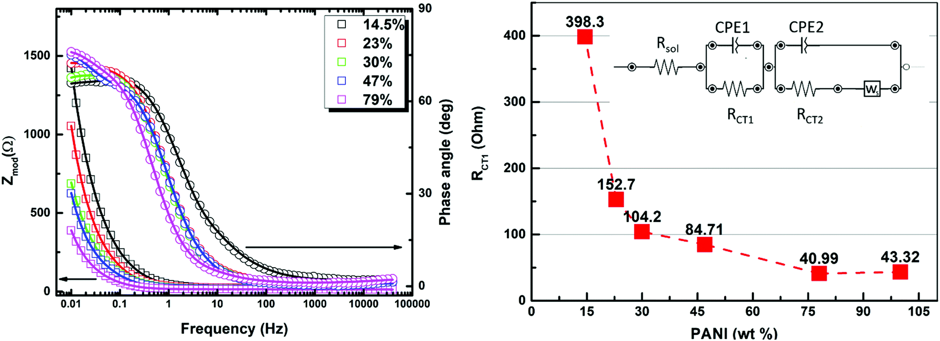
To gain deeper insight into the operating mechanism(s) resulting in the enhanced specific capacitance of the PANI in the prepared composites, electrochemical impedance spectroscopy (EIS) was utilized, with the results shown in Fig. 6. The EIS technique was employed in order to dissect the complex nature of the time-dependent processes using a complex frequency domain study. The Nyquist/Bode EIS data recorded within the frequency range of 50 kHz to 10 mHz at the open circuit potential with an AC perturbing signal of 10 mV were nicely fitted to an equivalent circuit with two time constants, using a modified Randle's circuit, as shown in Fig. 6. At relatively high frequency, the impedance of the system was found to be mostly dominated by the internal and interfacial resistances of the electrode along with the ohmic resistance of the electrolyte, represented by the resistor component (RSol) in the fitting parameters. In the medium to high frequency range, a distorted semicircle shape of the real versus imaginary components (Z′ and Z′′) of the impedance was noted, and was assigned to the charge-transfer resistance across the interface within the composite (RCT1) and the constant phase element (CPEDL) representing the double layer capacitance. Most significantly, the inter-chain charge transfer, represented by the RCT1 element, was found to drop significantly upon increasing the conducting PANI wt% (Table 1), matching the charge percolation threshold described earlier. This charge-transfer process, most likely representing charge hopping within the composite, is thought to dominate the overall charge transfer/storage mechanism within the composite and is in good agreement with the findings of the electrochemical CV section, vide supra. The two-sloped linear tail profile observed at relatively low frequency can be assigned to the short circuit terminus Warburg element, describing a finite length ion diffusion process across the electrode interface, accompanied with a second time constant. Such element is fairly utilized to describe the interlinked nature of the charge storage through an ion diffusion process within the voids of a porous film with finite thickness. The variations in the B parameter, which describes the diffusion time with relative concentration of the PANI within the composite matrix, reveals that the fastest diffusion process was recorded in the PANI concentration range of 30–47 wt%.
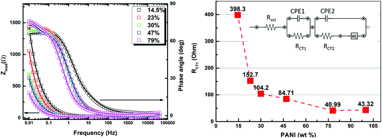 |
| | Fig. 6 EIS data and fitting of the samples containing different PANI wt% (left), and changes in the RCT2 element upon increased PANI wt% (right), where the inset shows the equivalent circuit used for fitting. | |
Table 1 The fitting parameters of the different elements of the equivalent circuit used in modeling the EIS data
| Composition (PANI wt%) |
14.5% |
23% |
30% |
47% |
79% |
100% |
Unit |
|
R
soln
|
10.63 |
17.81 |
16.46 |
15.24 |
9.666 |
10.69 |
Ohm |
|
R
CT1
|
398.3 |
152.7 |
104.2 |
84.71 |
40.99 |
43.32 |
Ohm |
|
C
CPE1
|
0.01047 |
0.02329 |
0.0353 |
0.02995 |
0.07901 |
0.07433 |
S*s^a |
|
n
CPE1
|
0.763 |
0.809 |
0.7858 |
0.8276 |
0.8498 |
0.7251 |
|
|
C
CPE2
|
0.0006259 |
0.00055 |
0.001813 |
0.00124 |
0.001104 |
0.001934 |
S*s^a |
|
n
CPE2
|
0.3714 |
0.3491 |
0.4446 |
0.5312 |
0.3702 |
0.4801 |
|
|
R
CT2
|
6. 105 |
5.496 |
1.554 |
1.106 |
3.701 |
2.002 |
Ohm |
|
Y
W|
|
0.0278 |
0.06563 |
0.1063 |
0.3411 |
0.1033 |
0.1047 |
S*s^(1/2) |
|
B
W|
|
0.3842 |
0.2168 |
0.1764 |
0.06827 |
0.3775 |
0.429 |
Sec^(1/2) |
The second charge transfer resistance (RCT2), was assigned to represent the charge transfer within the PANI chains. Considering the aforementioned fitted parameters, it is clear that the samples containing 23–30 wt% PANI seem to exhibit the optimum combination of low PANI–MOF interface resistance, low diffusion time, and moderate intra-chain charge transfer resistance within the PANI chains, making them the best candidates for maximizing the specific capacitance of the PANI. Indeed, this result is in close agreement with the demonstrated highest specific capacitance recorded for the 23 wt% composite in the CV measurements. Considering all such factors and the sudden drop in the porosity of the composite beyond the 23 wt% composition, it becomes evident that a delicate balance between establishing charge percolation pathways within the composite while simultaneously retaining good porosity is key to achieving targeted improvement in the specific capacitance of PANI.
Overall, it is clearly demonstrated that: (i) the presence of nanogens results in enhanced electrochemical performance most likely linked to facilitated ion diffusion impacting the shape of the CV scans, (ii) increasing the nanogen concentration results in an increase in the specific capacitance of PANI, and (iii) beyond the optimal composition, a drop in the specific capacitance is observed. Coupled with the results from EIS study, it is reasonable then to assume that increasing the nanogen concentration enhances ion diffusivity within the PANI matrix, thus resulting in a more accessible surface of the PANI chains for the electrolyte. However, increasing the concentration of the microporous, electrically non-conductive MOF beyond a certain saddle point results in an inflection in the specific capacitance. This drop in the specific capacitance upon an increase in the MOF content beyond an optimal value can be ascribed to tipping the balance between generating more accessible voids and decreasing the overall electrical conductivity of the composite. The decrease in the electrical conductivity of the composite when the MOF wt% increases is in agreement with the poor electrical conductivity of the MOF. This composition-electrical conductivity relationship was recently reported for the MOF doping of PANI, where electrical conductivity was found to drastically drop upon increasing the MOF wt% in the composite.29,53 It is worth noting that such previous attempts to prepare MOF–PANI composites were only concerned with the electrical conductivity of the composite or did not address the systematic variations in the MOF/PANI ratios and their impact on the specific capacitance of the PANI. Unwinding this tight entanglement between the porosity and electrical conductivity of the MOF–PANI composite was made possible by the systematic approach devised herein to result in the designable and controllable composition of the binary system PANI@MOF for successful improvement of the PANI specific capacitance. Noticeably, the highest specific capacitance value of 872 F g−1 for the composite with 23 wt% PANI is higher than other PANI forms prepared via wet chemistry methods, as shown in Table 2, and therefore presents a facile and tunable approach to enhance the pseudosupercapacitor characteristics of PANI, and is potentially a transferrable model to be exploited for other types of MOFs towards enhancing such properties of PANI and also other conductive polymers.
Table 2 Selected values of the PANI specific capacitance reported recently using wet chemistry polymerization techniques
| Sample |
Discharge rate |
Potential range (V) |
Specific capacitance (F g−1) |
Ref. |
| PANI@UiO-66-NH2 |
7 mV s−1 |
−0.1![[thin space (1/6-em)]](https://www.rsc.org/images/entities/char_2009.gif) :0.8 :0.8 |
872 |
This work |
| PANI |
10 mV s−1 |
−0.1:0.8 |
503 |
40
|
| PANI |
10 mV s−1 |
−0.2:1.0 |
283 |
48
|
| PANI |
5 mV s−1 |
0:0.85 |
187 |
49
|
| PANI–MnO2 |
|
|
330 |
|
| PANI nanofibers |
0.18 A g−1 |
0:0.8 |
548 |
50
|
| G/PANI nanoFiber |
100 mV s−1 |
−0.2:0.8 |
480 |
51
|
| De-doped PANI nanofibers |
2.5 A g−1 |
0–0.75 |
593 |
52
|
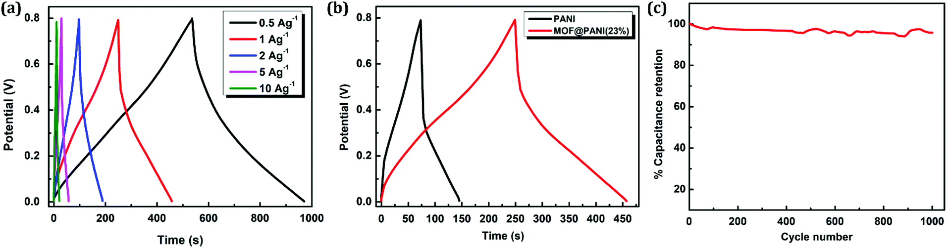
To further investigate the electrochemical performance of the composite, a two-electrode setup was assembled and analyzed using galvanostatic charge–discharge (GCD) measurements. The sample containing 23 wt% PANI was utilized in this supercapacitor characterization setup, where the material was drop cast on Ti electrodes separated by a porous membrane and 1 M H2SO4 was used as an electrolyte. The charge–discharge curves of the prepared supercapacitor were probed by varying the current density in the range of 0.5–10 A g−1, as shown in Fig. 7a, which demonstrates the nearly symmetric triangular shape of the GCD profile, indicating that the facilitated redox process is associated with the presence of nanogens in the matrix, facilitating ion diffusion from the bulk of the electrolyte to reach the solid–electrolyte interface. The specific capacitance of the electrode was calculated based on GCD data, where a normal dependence of the specific capacitance on the current density was observed with an obtained value of 345 F g−1 at a current density of 0.5 A g−1. Furthermore, comparison between the charge–discharge performance at the same current density between pristine PANI and the sample containing 23 wt% of the PANI clearly shows a longer time span for the GCD curve of the MOF@PANI composite, indicating a higher charge storage capacity for the MOF@PANI composite, as shown in Fig. 7b. Additionally, excellent retention of the specific capacitance over 1000 cycles at a current density of 1 A g−1 was demonstrated, as shown in Fig. 7c, where the MOF@PANI retained over 96% of its initial capacitance, even after 1000 cycles, indicating the robustness of the system, a performance that surpasses that of pristine PANI, which commonly shows quick decay in capacity over a relatively small number of cycles.54–57
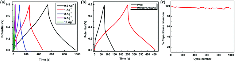 |
| | Fig. 7 Two-electrode setup characterization of the MOF@PANI (23 wt%) showing (a) the GCD profile at different charging current density for the MOF@PANI_23 wt%, (b) GCD response comparison with PANI at a current density of 1 A g−1, and (c) capacitance retention over 1000 cycles. | |
Conclusion
In conclusion, we report a facile and potentially transferrable model to enhance the pseudocapacitor behavior of PANI through the incorporation of MOF nanocrystals, as a microporous filler (nanogens), into the PANI matrix, providing ion-diffusion channels within the matrix to enhance the electrolyte diffusion to reach the PANI chains, as compared to bulk non-porous PANI prepared via a wet chemistry synthesis. Through a systematic investigation to probe the effect(s) of varying the MOF content within the MOF@PANI composites, an optimal composition was attained at a weight ratio of 23:67 (PANI:MOF), which demonstrated the highest specific capacitance for PANI among the investigated composites. It is argued that this optimal composition provides for enhanced diffusivity of the electrolyte species towards the PANI–electrolyte interface through the microporous MOF filler (nanogens), while maintaining good electrical conductivity of the overall composite (provided by the PANI chains). This approach paves the way for a large family of MOFs that demonstrate a wide variety of pore dimensions and chemistry, as well as stability in different electrolytes, to be directly implemented as nanogens to boost the electrochemical characteristics of another family of readily available conductive polymers, addressing the limitations of both types of drastically different materials to prepare well-designed composite materials that exhibit far-enhanced properties compared with their parents materials.
Experimental
All reagents were of commercial grade and used without further purification. Electrochemical measurements were carried out in a three-electrode system using a calomel electrode as the reference electrode (Hanna Instruments, HI 5412, 3.5 M KCl), glassy-carbon electrode as the working electrode, and Pt wire as the counter electrode. Measurements were recorded on a Bio-Logic SP-50 potentiostat/galvanostat and data were recorded using the EC-lab software. FTIR spectra were recorded on a ThermoScientific iS10 spectrophotometer. Activated carbon was purchased from Carlo Erba, aniline (99.5%, extra pure) was purchased from Acros Organics, ammonium persulfate (APS, acs reagent, >98%) was purchased from Sigma-Aldrich, ZrCl4 (anhydrous, >98%) was purchased from Acros, 2-aminoterephthalic acid (99%) was purchased from Acros organics, HCl (37%) was purchased from Honeywell, N-methyl-2-pyrrolidone (NMP) was purchased from Sisco Research Laboratories, N,N′-dimethylformamide (DMF, analytical reagent grade, 99.99%) and acetonitrile (ACN, HPLC gradient grade) was purchased from Fisher Chemical. Aniline was purified by distillation under reduced pressure prior to use.
Synthesis of PANI
In a clean glass vial, 15 mL of APS (100 mM in 1 M HCl) was added into 10 mL of aniline (100 mM in 1 M HCl) while vigorously stirring and was left to stir at room temperature for 20 h. The formed precipitate was filtered and washed with 50 mL of deionized water twice and left to dry under vacuum at room temperature to give the product in a yield of 40 mg.
Synthesis of the UiO-66-NH2 (MOF)
A previously published procedure for the synthesis of UiO-66-NH2 using HCl as a modulator was utilized.58
Synthesis of MOF@PANI_X
For the UiO-66-NH2@PANI composites, where X represents the PANI wt% in the composite, a similar procedure to the synthesis of PANI described above was used, but varying the weight of UiO-66-NH2 dry powder dispersed briefly in the aniline solution using ultrasonication for 15 minutes and the APS was added prior to leaving the mixture to stir at 550 rpm for 20 h at room temperature (Table 3).
Table 3 Amounts of precursor solutions and MOF filler used for the preparation of the MOF@PANI composites and their respective yields
| Sample |
Aniline (mL) |
APS (mL) |
UiO-66-NH2 (mg) |
Yield (mg) |
| MOF@PANI_14.5 |
10 |
10 |
122 |
142.8 |
| MOF@PANI_23 |
10 |
10 |
82 |
107.1 |
| MOF@PANI_30 |
10 |
10 |
62 |
88.7 |
| MOF@PANI_47 |
10 |
10 |
40 |
75.6 |
| MOF@PANI_79 |
10 |
10 |
10 |
47.1 |
General procedure for ink preparation
For each sample, ∼8.1 mg of the active material was well ground in an agate mortar, to which ∼2.6 mg of activated carbon was added and the resultant mixture was ground for 10 minutes. The solid mixture was then added to a solution of ∼0.8 mg of PVDF dissolved in 1 mL of NMP. The solution mixture was then sonicated for 15 minutes, then 10 μL was cast onto a polished glassy carbon electrode and left at 60 °C until dry. Another 10 μL was cast and dried before electrochemical testing. The reference electrode was a calomel electrode (3.5 M KCl), and a platinum wire was used as the counter electrode.
Specific capacitance calculations
CV measurements were performed from −0.2 to 0.8 V at scan rates ranging from 10 to 250 mV s−1. The specific capacitance (C) (F g−1) of the PANI in the different composites was calculated from the CV at a scan rate 10 mV s−1 and derived from the following equation:
where I (mA cm−2 V−1) is the integrated peak area, V is the potential window, A is the electrode surface area, SC is the scan rate, and m (mg) is the mass of PANI in the sample under investigation.
Two-electrode setup
Galvanostatic charge–discharge cycles were recorded on a Bio-Logic SP-50 potentiostat/galvanostat and the reported specific charge was calculated using the EC-lab software utilizing the mass of one electrode of the assembly. To prepare the ink, 8 mg of the MOF@PANI (23%) was ground with 2.6 mg of activated carbon and the solids were suspended in 1 mL of PVDF (0.79 mg) in NMP solution via ultrasonication. 200 μL of the ink was then cast on each of the Ti electrodes and left to dry at 60 °C for 2 h. 1 M H2SO4 was used as the electrolyte.
Electrochemical impedance spectroscopy (EIS) measurements
EIS measurements were conducted on similarly prepared ink as that used in the CV measurements using a PalmSens4 potentiostat galvanostat in a three-electrode system in 1 M HCl aqueous electrolyte, using GCE as the working electrode, a calomel reference electrode (3.5 M KCl), and a platinum wire as the counter electrode. All measurements were conducted at open circuit potential covering a frequency range from 10 mHz to 50 kHz, at an AC perturbing signal of 10 mV.
Conflicts of interest
There are no conflicts to declare.
Acknowledgements
We acknowledge the financial support of the Zewail City of Science and Technology (ZC001-19).
References
- O. K. Farha, I. Eryazici, N. C. Jeong, B. G. Hauser, C. E. Wilmer, A. A. Sarjeant, R. Q. Snurr, S. T. Nguyen, A. Ö. Yazaydın and J. T. Hupp, Metal–Organic Framework Materials with Ultrahigh Surface Areas: Is the Sky the Limit?, J. Am. Chem. Soc., 2012, 134(36), 15016–15021 CrossRef CAS PubMed.
-
J.-X. Jiang and A. I. Cooper, Microporous Organic Polymers: Design, Synthesis, and Function. in Functional Metal-Organic Frameworks: Gas Storage, Separation and Catalysis, Schröder, M., ed. Springer Berlin Heidelberg, Berlin, Heidelberg, 2010, pp 1–33 Search PubMed.
- A. P. Côté, A. I. Benin, N. W. Ockwig, M. Keeffe, A. J. Matzger and O. M. Yaghi, Porous, Crystalline, Covalent Organic Frameworks, Science, 2005, 310(5751), 1166 CrossRef.
- Y. Byun, S. H. Je, S. N. Talapaneni and A. Coskun, Advances in Porous Organic Polymers for Efficient Water Capture, Chem. – Eur. J., 2019, 25(44), 10262–10283 CrossRef CAS.
- M. Mon, R. Bruno, J. Ferrando-Soria, D. Armentano and E. Pardo, Metal–organic framework technologies for water remediation: towards a sustainable ecosystem, J. Mater. Chem. A, 2018, 6(12), 4912–4947 RSC.
- D. Farrusseng, S. Aguado and C. Pinel, Metal–Organic Frameworks: Opportunities for Catalysis, Angew. Chem., Int. Ed., 2009, 48(41), 7502–7513 CrossRef CAS PubMed.
- R. R. Haikal, M. H. Hassan and M. H. Alkordi, Microporous Solids En Route to Heterogeneous Electrocatalysis: The Oxygen Reduction Reaction, Energy Technol., 2020, 8(3), 1900964 CrossRef CAS.
- P. Kaur, J. T. Hupp and S. T. Nguyen, Porous Organic Polymers in Catalysis: Opportunities and Challenges, ACS Catal., 2011, 1(7), 819–835 CrossRef CAS.
- Z. Chang, D.-S. Zhang, Q. Chen and X.-H. Bu, Microporous organic polymers for gas storage and separation applications, Phys. Chem. Chem. Phys., 2013, 15(15), 5430–5442 RSC.
- Y. Lin, C. Kong, Q. Zhang and L. Chen, Metal-Organic Frameworks for Carbon Dioxide Capture and Methane Storage. Advanced Energy, Materials, 2017, 7(4), 1601296 Search PubMed.
- L. Wang, Y. Han, X. Feng, J. Zhou, P. Qi and B. Wang, Metal–organic frameworks for energy storage: Batteries and supercapacitors, Coord. Chem. Rev., 2016, 307, 361–381 CrossRef CAS.
- T. Nezakati, A. Seifalian, A. Tan and A. M. Seifalian, Conductive Polymers: Opportunities and Challenges in Biomedical Applications, Chem. Rev., 2018, 118(14), 6766–6843 CrossRef CAS PubMed.
- C. O. Baker, X. Huang, W. Nelson and R. B. Kaner, Polyaniline nanofibers: broadening applications for conducting polymers, Chem. Soc. Rev., 2017, 46(5), 1510–1525 RSC.
- P. Singh and S. K. Shukla, Advances in polyaniline-based nanocomposites, J. Mater. Sci., 2020, 55(4), 1331–1365 CrossRef CAS.
- T. Sen, S. Mishra and N. G. Shimpi, Synthesis and sensing applications of polyaniline nanocomposites: a review, RSC Adv., 2016, 6(48), 42196–42222 RSC.
- S. Grover, S. Goel, R. B. Marichi, V. Sahu, G. Singh and R. K. Sharma, Polyaniline All Solid-State Pseudocapacitor: Role of Morphological Variations in Performance Evolution, Electrochim. Acta, 2016, 196, 131–139 CrossRef CAS.
- T. Liu, L. Finn, M. Yu, H. Wang, T. Zhai, X. Lu, Y. Tong and Y. Li, Polyaniline and Polypyrrole Pseudocapacitor Electrodes with Excellent Cycling Stability, Nano Lett., 2014, 14(5), 2522–2527 CrossRef CAS PubMed.
- A. Eftekhari, L. Li and Y. Yang, Polyaniline supercapacitors, J. Power Sources, 2017, 347, 86–107 CrossRef CAS.
- L. Chen, J. Wu, A. Zhang, A. Zhou, Z. Huang, H. Bai and L. Li, One-step synthesis of polyhydroquinone–graphene hydrogel composites for high performance supercapacitors, J. Mater. Chem. A, 2015, 3(31), 16033–16039 RSC.
- R. R. Haikal, A. B. Soliman, M. Amin, S. G. Karakalos, Y. S. Hassan, A. M. Elmansi, I. H. Hafez, M. R. Berber, A. Hassanien and M. H. Alkordi, Synergism of carbon nanotubes and porous-organic polymers (POPs) in CO2 fixation: One-pot approach for bottom-up assembly of tunable heterogeneous catalyst, Appl. Catal., B, 2017, 207, 347–357 CrossRef CAS.
- M. H. Hassan, A. B. Soliman, W. A. Elmehelmey, A. A. Abugable, S. G. Karakalos, M. Elbahri, A. Hassanien and M. H. Alkordi, A Ni-loaded, metal–organic framework–graphene composite as a precursor for in situ electrochemical deposition of a highly active and durable water oxidation nanocatalyst, Chem. Commun., 2019, 55(1), 31–34 RSC.
- M. H. Hassan, M. H. Alkordi and A. Hassanien, Probing the conductivity of metal-organic framework-graphene nanocomposite, Mater. Lett., 2019, 246, 13–16 CrossRef CAS.
- M. E. A. Safy, R. R. Haikal, B. Elshazly, A. Hamdy, F. Ali, A. A. Maarouf and M. H. Alkordi, Charge percolation in metal-organic framework (HKUST-1)–graphene nanocomposites, Appl. Mater. Today, 2020, 19, 100604 CrossRef.
- W. Ye, K. Wang, W. Yin, W. Chai, Y. Rui and B. Tang, A novel Zr-MOF-based and polyaniline-coated UIO-67@Se@PANI composite cathode for lithium–selenium batteries, Dalton Trans., 2019, 48(27), 10191–10198 RSC.
- K. E. Ramohlola, G. R. Monana, M. J. Hato, K. D. Modibane, K. M. Molapo, M. Masikini, S. B. Mduli and E. I. Iwuoha, Polyaniline-metal organic framework nanocomposite as an efficient electrocatalyst for hydrogen evolution reaction, Composites, Part B, 2018, 137, 129–139 CrossRef CAS.
- S. Jia, Q. Wang and S. Wang, Ni-MOF/PANI-Derived CN-Doped NiO Nanocomposites for High Sensitive Nonenzymic Electrochemical Detection, J. Inorg. Organomet. Polym. Mater., 2021, 31(2), 865–874 CrossRef CAS.
- Q. Cheng, K. Tao, X. Han, Y. Yang, Z. Yang, Q. Ma and L. Han, Ultrathin Ni-MOF nanosheet arrays grown on polyaniline decorated Ni foam as an advanced electrode for asymmetric supercapacitors with high energy density, Dalton Trans., 2019, 48(13), 4119–4123 RSC.
- M. Z. Iqbal, M. M. Faisal, S. R. Ali, S. Farid and A. M. Afzal, Co-MOF/polyaniline-based electrode material for high performance supercapattery devices, Electrochim. Acta, 2020, 346, 136039 CrossRef CAS.
- L. Shao, Q. Wang, Z. Ma, Z. Ji, X. Wang, D. Song, Y. Liu and N. Wang, A high-capacitance flexible solid-state supercapacitor based on polyaniline and Metal-Organic Framework (UiO-66) composites, J. Power Sources, 2018, 379, 350–361 CrossRef CAS.
- L. Wang, X. Feng, L. Ren, Q. Piao, J. Zhong, Y. Wang, H. Li, Y. Chen and B. Wang, Flexible Solid-State Supercapacitor Based on a Metal–Organic Framework Interwoven by Electrochemically-Deposited PANI, J. Am. Chem. Soc., 2015, 137(15), 4920–4923 CrossRef CAS.
- P.-Y. Liu, J.-J. Zhao, Z.-P. Dong, Z.-L. Liu and Y.-Q. Wang, Interwoving polyaniline and a metal-organic framework grown in situ for enhanced supercapacitor behavior, J. Alloys Compd., 2021, 854, 157181 CrossRef CAS.
- Y.-D. Song, W. H. Ho, Y.-C. Chen, J.-H. Li, Y.-S. Wang, Y.-J. Gu, C.-H. Chuang and C.-W. Kung, Selective Formation of Polyaniline Confined in the Nanopores of a Metal–Organic Framework for Supercapacitors, Chem. – Eur. J., 2021, 27(10), 3560–3567 CrossRef CAS.
- X. Zhang, D. Li, C. Dong, J. Shi and Y. Xu, The synergistic supercapacitive performance of Mo-MOF/PANI and its electrochemical impedance spectroscopy investigation, Mater. Today Commun., 2019, 21, 100711 CrossRef CAS.
- A. J. Epstein, J. M. Ginder, F. Zuo, H. S. Woo, D. B. Tanner, A. F. Richter, M. Angelopoulos, W. S. Huang and A. G. MacDiarmid, Insulator-to-metal transition in polyaniline: Effect of protonation in emeraldine, Synth. Met., 1987, 21(1), 63–70 CrossRef CAS.
- C. Peng, D. Hu and G. Z. Chen, Theoretical specific capacitance based on charge storage mechanisms of conducting polymers: Comment on ‘Vertically oriented arrays of polyaniline nanorods and their super electrochemical properties’, Chem. Commun., 2011, 47(14), 4105–4107 RSC.
- F. Miao, C. Shao, X. Li, N. Lu, K. Wang, X. Zhang and Y. Liu, Polyaniline-coated electrospun carbon nanofibers with high mass loading and enhanced capacitive performance as freestanding electrodes for flexible solid-state supercapacitors, Energy, 2016, 95, 233–241 CrossRef CAS.
- H. Xu, X. Li and G. Wang, Polyaniline nanofibers with a high specific surface area and an improved pore structure for supercapacitors, J. Power Sources, 2015, 294, 16–21 CrossRef CAS.
- J. Li, Y. Ren, Z. Ren, S. Wang, Y. Qiu and J. Yu, Aligned polyaniline nanowires grown on the internal surface of macroporous carbon for supercapacitors, J. Mater. Chem. A, 2015, 3(46), 23307–23315 RSC.
- K. Zhang, L. L. Zhang, X. S. Zhao and J. Wu, Graphene/Polyaniline Nanofiber Composites as Supercapacitor Electrodes, Chem. Mater., 2010, 22(4), 1392–1401 CrossRef CAS.
- D. S. Dhawale, A. Vinu and C. D. Lokhande, Stable nanostructured polyaniline electrode for supercapacitor application, Electrochim. Acta, 2011, 56(25), 9482–9487 CrossRef CAS.
- M. Kandiah, M. H. Nilsen, S. Usseglio, S. Jakobsen, U. Olsbye, M. Tilset, C. Larabi, E. A. Quadrelli, F. Bonino and K. P. Lillerud, Synthesis and Stability of Tagged UiO-66 Zr-MOFs, Chem. Mater., 2010, 22(24), 6632–6640 CrossRef CAS.
- J. S. Tan, X. M. Liu, B. Yu, H. L. Cong, Z. J. Li, Y. C. Zhao, Y. C. Lian and X. Y. Guo, Fabrication of PAN Hollow Fiber Ultrafiltration Membrane with Salt Porogen, Adv. Mater. Res., 2013, 669, 185–188 Search PubMed.
- R. T. Tran, E. Naseri, A. Kolasnikov, X. Bai and J. Yang, A new generation of sodium chloride porogen for tissue engineering, Biotechnol. Appl. Biochem., 2011, 58(5), 335–344 CrossRef CAS.
- A.-C. Chao, S.-H. Yu and G.-S. Chuang, Using NaCl particles as porogen to prepare a highly adsorbent chitosan membranes, J. Membr. Sci., 2006, 280(1), 163–174 CrossRef CAS.
- M. E. A. Safy, M. Amin, R. R. Haikal, B. Elshazly, J. Wang, Y. Wang, C. Wöll and M. H. Alkordi, Probing the Water Stability Limits and Degradation Pathways of Metal–Organic Frameworks, Chem. – Eur. J., 2020, 26(31), 7109–7117 CrossRef CAS PubMed.
- S. Wang, L. Ma, M. Gan, S. Fu, W. Dai, T. Zhou, X. Sun, H. Wang and H. Wang, Free-standing 3D graphene/polyaniline composite film electrodes for high-performance supercapacitors, J. Power Sources, 2015, 299, 347–355 CrossRef CAS.
- Q. Wang, L. Shao, Z. Ma, J. Xu, Y. Li and C. Wang, Hierarchical porous PANI/MIL-101 nanocomposites based solid-state flexible supercapacitor, Electrochim. Acta, 2018, 281, 582–593 CrossRef CAS.
- M. Liu, Y.-E. Miao, C. Zhang, W. W. Tjiu, Z. Yang, H. Peng and T. Liu, Hierarchical composites of polyaniline–graphene nanoribbons–carbon nanotubes as electrode materials in all-solid-state supercapacitors, Nanoscale, 2013, 5(16), 7312–7320 RSC.
- X. Zhang, L. Ji, S. Zhang and W. Yang, Synthesis of a novel polyaniline-intercalated layered manganese oxide nanocomposite as electrode material for electrochemical capacitor, J. Power Sources, 2007, 173(2), 1017–1023 CrossRef CAS.
- H. Guan, L.-Z. Fan, H. Zhang and X. Qu, Polyaniline nanofibers obtained by interfacial polymerization for high-rate supercapacitors, Electrochim. Acta, 2010, 56(2), 964–968 CrossRef CAS.
- P. Sivaraman, R. K. Kushwaha, K. Shashidhara, V. R. Hande, A. P. Thakur, A. B. Samui and M. M. Khandpekar, All solid supercapacitor based on polyaniline and crosslinked sulfonated poly[ether ether ketone], Electrochim. Acta, 2010, 55(7), 2451–2456 CrossRef CAS.
- C. Bian and A. Yu, De-doped polyaniline nanofibres with micropores for high-rate aqueous electrochemical capacitor, Synth. Met., 2010, 160(13), 1579–1583 CrossRef CAS.
- J. Shanahan, D. S. Kissel and E. Sullivan, PANI@UiO-66 and PANI@UiO-66-NH2 Polymer-MOF Hybrid Composites as Tunable Semiconducting Materials, ACS Omega, 2020, 5(12), 6395–6404 CrossRef CAS.
- Z. Hou, L. Kong, S. Zou, L. Zhao and L. Yang, Microstructure and electrochemical performance of 3D hierarchical porous graphene/polyaniline composites, RSC Adv., 2020, 10(5), 2989–2997 RSC.
- Y. Xi, G. Wei, X. Liu, M. Pang, L. Liu, Y. Yang, Y. Ji, V. Y. Izotov, N. I. Klyui and W. Han, Enhancing the cycling stability of the polyaniline hybrids benefited from the hollow manganese dioxide/acetylene black skeleton, Chem. Eng. J., 2016, 290, 361–370 CrossRef CAS.
- X. Wang, D. Liu, J. Deng, X. Duan, J. Guo and P. Liu, Improving cyclic stability of polyaniline by thermal crosslinking as electrode material for supercapacitors, RSC Adv., 2015, 5(96), 78545–78552 RSC.
- K. Wang, L. Li, Y. Liu, C. Zhang and T. Liu, Constructing a “Pizza-Like” MoS2/Polypyrrole/Polyaniline Ternary Architecture with High Energy Density and Superior Cycling Stability for Supercapacitors, Adv. Mater. Interfaces, 2016, 3(19), 1600665 CrossRef.
- M. J. Katz, Z. J. Brown, Y. J. Colón, P. W. Siu, K. A. Scheidt, R. Q. Snurr, J. T. Hupp and O. K. Farha, A facile synthesis of UiO-66, UiO-67 and their derivatives, Chem. Commun., 2013, 49(82), 9449–9451 RSC.
Footnote |
| † These authors contributed equally to this work. |
|
| This journal is © The Royal Society of Chemistry 2022 |
Click here to see how this site uses Cookies. View our privacy policy here. 
 Open Access Article
 This Open Access Article is licensed under a Creative Commons Attribution-Non Commercial 3.0 Unported Licence
 a,
Aya Mohamed
Ali
a,
Ahmed B.
Soliman
b,
Mady
ElBahri
b and
Mohamed H.
Alkordi
a,
Aya Mohamed
Ali
a,
Ahmed B.
Soliman
b,
Mady
ElBahri
b and
Mohamed H.
Alkordi