Grass-like NixSey nanowire arrays shelled with NiFe LDH nanosheets as a 3D hierarchical core–shell electrocatalyst for efficient upgrading of biomass-derived 5-hydroxymethylfurfural and furfural†
Yan
Zhong
 a,
Ru-Quan
Ren
a,
Jian-Bo
Wang
a,
Yi-Yi
Peng
a,
Qiang
Li
a,
Ru-Quan
Ren
a,
Jian-Bo
Wang
a,
Yi-Yi
Peng
a,
Qiang
Li
 *b and
Yong-Ming
Fan
 *a
*a
aKey Laboratory of Lignocellulosic Chemistry, College of Material Science and Technology, Beijing Forestry University, Beijing, 100083, China. E-mail: fanym@bjfu.edu.cn; Tel: +86 185 15301003
bCollege of Science, Beijing Forestry University, Beijing 100083, China. E-mail: liqiang@bjfu.edu.cn; Tel: +86 137 18679671
First published on 5th November 2021
Abstract
Electrocatalytic upgrading of biomass represents a promising way for the green synthesis of value-added fine chemicals. Rational construction of highly active and low-cost electrocatalysts with superior durability is of great importance for promoting this electrochemical process. In this work, we reported a novel 3D hierarchical NixSey–NiFe layered double hydroxide (LDH) core–shell nanostructure in situ grown on Ni foam (NixSey–NiFe@NF) for efficient electrocatalytic oxidation of biomass-derived 5-hydroxymethylfurfural (HMF) to 2,5-furandicarboxylic acid (FDCA) and furfural (FUR) to furoic acid (FurAc), respectively. By virtue of the excellent electrical conductivity and good mechanical strength of the NixSey nanowire core, abundant exposed active sites of the NiFe LDH nanosheet shell, and the open structure of the hierarchical nanoarrays, the integrated core–shell NixSey–NiFe LDH@NF electrode exhibited outstanding catalytic performance for HMF and FUR oxidation by obtaining considerable yields of FDCA (99.3%) and FurAc (99.7%) with high faradaic efficiency (FE) for FDCA (98.9%) and FurAc (99.5%), as well as superior stability retaining 96.7% FE for FDCA and 97.1% FE for FurAc after six successive electrolysis cycles. This work offers an effective approach to engineer novel electrocatalysts towards efficient upgrading of biomass-derived platform chemicals.
1. Introduction
The rapid depletion of limited fossil fuels has led to growing interest in the utilization of biomass which is a renewable feedstock for production of fuels and chemicals.1,2 As versatile bio-derived C6 and C5 platform molecules, 5-hydroxymethylfurfural (HMF) and furfural (FUR) have been considered as the key precursors for producing liquid fuels, fine chemicals, plastics and pharmaceuticals.3,4 Among the high-value derivatives from oxidation of HMF and FUR, 2,5-furandicarboxylic acid (FDCA) and furoic acid (FurAc) have gained considerable attention, as FDCA is a vital monomer for producing bio-based polyesters (alternatives to petrochemical-based polyethylene terephthalate (PET))5 while FurAc can work as an excellent feedstock for synthetic resins, medicines, and pesticides as well as fine chemicals.6 The conventional route for FDCA and FurAc synthesis is through selective oxidation of HMF or FUR in thermo-catalytic systems, which is typically carried out by utilizing oxidants or noble metal catalysts (e.g., Pt, Au, Pd, Ru) at elevated temperature with high-pressure O2.7–11 These high-cost and energy-demanding approaches prompt considerable efforts to develop alternative methods for efficiently producing FDCA and FurAc.Electrocatalytic oxidation is an appealing green technology which can be performed in aqueous solution by tuning the applied potential under ambient conditions without requiring extra O2 or oxidants.12 As a result, electrocatalytic oxidation of HMF and FUR has attracted increasing attention in recent years and enormous efforts have been made to develop efficient electrocatalysts to facilitate this electrooxidation process. For example, some noble metal-based catalysts including Au, Pt and Pd were found to be active for electrochemical oxidation of HMF or FUR,13,14 but due to their high costs and limited reserves, an increasing number of studies on non-noble metal-based catalysts have been reported. Recently, some transition metal catalysts such as NiOOH,15 Ni2P,16 MnOx,17 NiCo2O4,18 and CuCo2O4 (ref. 19) were developed and they exhibited high activity towards HMF or FUR electrooxidation, which was comparable with that of some reported precious metal catalysts. However, due to the relatively low electrical conductivity of these materials, high overpotential was usually required for reaching the desired current density in the electrochemical process.20 On the other hand, they usually showed poor catalytic durability due to the aggregation of nanoparticles or structural instability.21 Achieving high catalytic activity and stability simultaneously remains challenging and there is an urgent need for improvement of electrocatalysts for HMF and FUR oxidation.
Layered double hydroxides (LDHs), consisting of positively charged host layers (brucite-like M(OH)6 octahedra) and interlayer anions, have been regarded as promising two-dimensional (2D) materials in the heterogeneous catalysis field owing to their favorable activity, tunable composition, low cost, and ease of scale-up.22 Notably, NiFe LDHs were found to have outstanding OER activity in alkaline electrolyte and they also exhibited tremendous potential for efficient electrocatalytic oxidation of HMF.23–25 However, their performance is limited by their sparse exposed active sites and poor electrical conductivity. To improve the intrinsic activity of LDH-based catalysts, several strategies such as exfoliation to obtain ultrathin nanosheets, modulation of the surface/interface defect structure, and ion intercalation have been employed and demonstrated to be effective.26 But these synthetic methods are either time consuming and expensive or require polymer binders or conductive additives, which are not favorable for large-scale application.22 Recent research has indicated that coupling LDHs with other conductive nanomaterials such as metallic sulfides,27,28 metallic phosphides29 and carbon-based materials30 to construct a self-supporting electrode is a simple and cost-effective way to improve the active surface area of LDHs and enhance their conductivity. From this viewpoint, transition metal selenides (MxSey, M = Ni, Fe, Co) have been investigated as a fascinating type of electroactive material because of their desirable electrical conductivity (the electronic conductivity of elemental Se is 1 × 10⁻³ S m−1) compared to transition metal oxides or sulfides.31 Among them, nickel selenides have attracted extensive research interest owing to their metal-like electrical conductivity, high theoretical specific capacitance, and high catalytic activity in water splitting.32 Various synthetic methods endowed nickel selenides with a controllable morphology and structure, which enable them to combine with other active materials. On the other hand, hierarchical architectures constructed from different materials are of great interest since the enlarged surface area can provide more active sites, the nanointerfaces between the coupling materials can facilitate the charge transfer, and unique nanostructures can enhance the long-term stability.33 Therefore, given the excellent conductivity of nickel selenides and the impressive activity of NiFe LDHs for HMF oxidation, it is highly desired to rationally design a hierarchical nanostructure integrating a nickel selenide with a NiFe LDH to further improve the catalytic activity and stability of electrocatalysts for HMF and FUR electrooxidation.
Herein, we design and successfully fabricate a novel 3D hierarchical NixSey–NiFe LDH core–shell architecture in situ grown on Ni foam (denoted as NixSey–NiFe LDH@NF) by assembling thin NiFe LDH nanosheets on grass-like NixSey nanowire arrays. As a non-precious electrocatalyst, the core–shell NixSey–NiFe LDH@NF exhibited excellent catalytic performance for HMF and FUR oxidation by obtaining considerable yields of FDCA (99.3%) and FurAc (99.7%) with high faradaic efficiency (FE) for FDCA (98.9%) and FurAc (99.5%), as well as superior stability retaining 96.7% FE for FDCA and 97.1% FE for FurAc after six successive electrolysis cycles, which could be attributed to the excellent electrical conductivity and good mechanical strength of the NixSey nanowire core, abundant exposed active sites of the NiFe LDH nanosheet shell, and the open structure of the hierarchical nanoarrays. This work provides a rational strategy to design efficient and durable electrocatalysts for green synthesis of high value-added products from biomass-derived platform chemicals.
2. Experimental
2.1. Chemicals and materials
All chemicals were used as received without further purification. 5-Hydroxymethylfurfural (HMF, 99%), 5-hydroxymethyl-2-furancarboxylic acid (HMFCA, 98%), 5-formylfuran-2-carboxylic acid (FFCA, 98%), 2,5-diformylfuran (DFF, 98%), 2,5-furandicarboxylic acid (FDCA, 98%), furfural (FUR, 99%), furoic acid (FurAc, 98%), selenium powder (99%), sodium borohydride (NaBH4, 98%), nickel nitrate (Ni(NO3)2·6H2O, 98%) and iron sulfate heptahydrate (FeSO4·7H2O, 99%) were purchased from Shanghai Aladdin Biochemical Technology Co., Ltd. Anhydrous ethanol was purchased from Shanghai Titan Scientific Co., Ltd. Commercial nickel foam (NF) was obtained from Shenzhen Kejing Star Technology Co., Ltd. Water was deionized (18.2 MΩ cm−1) with a PALL Cascada I system and used throughout the experiments.2.2. Synthesis of grass-like NixSey nanowire arrays on NF
The grass-like NixSey nanowire arrays grown on Ni foam (NixSey@NF) were synthesized by in situ selenization of Ni foam. Typically, a large piece of Ni foam (NF) was cut into the desired sizes (1.0 cm × 1.5 cm) and then cleaned ultrasonically in acetone, 3 mol L−1 HCl solution, deionized water, and absolute ethanol sequentially. Afterward, the pre-treated NF was dried in a vacuum and stored for further use. To prepare NaHSe solution, 110 mg Se powder was carefully added into 6 mL deionized water containing 130 mg NaBH4, and after gentle stirring under a N2 flow for several minutes, a clear NaHSe solution was obtained. Then, 34 mL absolute ethanol was added into the NaHSe solution under the protection of a N2 flow, and as soon as the mixture became a diluted milk-like liquid, it was transferred into a 50 mL Teflon-lined stainless-steel autoclave with a piece of pre-treated NF. The autoclave was then sealed and heated at 140 °C for 12 h, and afterward, it was naturally cooled to room temperature. Finally, the NF was taken out and cleaned with deionized water and absolute ethanol several times and then dried in a vacuum at 60 °C for 12 h. The loading mass of NixSey on NF was about 7.2 mg cm−2.2.3. Synthesis of the 3D core–shell NixSey–NiFe LDH@NF
The 3D core–shell NixSey–NiFe LDH@NF electrocatalyst was fabricated by direct electrodeposition of NiFe LDH on the as-prepared NixSey nanowire arrays.34,35 Briefly, 0.15 mol L−1 Ni(NO3)2·6H2O and 0.15 mol L−1 FeSO4·7H2O were dissolved in 50 mL deionized water to form a green mixture solution as electrolyte. The electrodeposition was conducted in a three-electrode system by using NixSey@NF, a Pt sheet, and a saturated calomel electrode (SCE) as the working, counter, and reference electrodes, respectively. The electrodeposition potential was −1.0 V (vs. SCE), and different deposition times of 30 s, 60 s, and 90 s were used to control the morphology of the samples, which were marked as NixSey–NiFe LDH@NF-30s, NixSey–NiFe LDH@NF-60s, and NixSey–NiFe LDH@NF-90s, respectively. After electrodeposition, the samples were carefully rinsed several times with deionized water and absolute ethanol and then dried in a vacuum at 60 °C for 12 h. In contrast, pure NiFe LDH was also grown on Ni foam by the same electrodeposition method. The loading mass of NixSey–NiFe LDH-60s on NF was about 8.3 mg cm−2 and that of NiFe LDH on NF was about 1.8 mg cm−2.2.4. Characterization
The X-ray diffraction (XRD) data of the as-prepared samples were collected on a Bruker D8 Advance X-ray diffractometer with Cu Kα radiation in a range of 10° to 80°. The morphology, chemical composition and crystal structure of the samples were investigated by using a ZEISS Gemini 300 scanning electron microscope (SEM) and a JEOL JEM 2200FS transmission electron microscope (TEM) capable of a high-resolution transmission electron microscopy (HRTEM) study, energy dispersive spectroscopy (EDS) analysis and selected area electron diffraction (SAED). The X-ray photoelectron spectroscopy (XPS) data of the samples were acquired on a Thermo Scientific K-Alpha spectrometer with Al Kα radiation, and all binding energy values were charge-corrected to the C1s signal (284.6 eV).2.5. Electrochemical methods
Electrochemical tests were performed at room temperature in a standard three-electrode system with the as-synthesized electrocatalysts, a Pt sheet, and Hg/HgO used as working, counter, and reference electrodes, respectively. The data were recorded using a CHI 660E electrochemical workstation (CH Instruments, Inc., Shanghai, China). The anode and cathode compartments were separated by an anion exchange membrane (Fumasep® FAA-3-PK-130 from Fumatech). All the potentials presented versus Hg/HgO in this work were calibrated to a reversible hydrogen electrode (RHE) based on the Nernst equation:36| Evs.RHE = Evs.Hg/HgO + 0.095 + 0.059 pH | (1) |
Linear sweep voltammetry (LSV) tests were carried out at a scan rate of 5 mV s−1 in 1.0 M KOH electrolyte with and without HMF or FUR. The LSV curves were reported with iR compensation. The electrochemically active surface area (ECSA) of the electrodes was evaluated from electrochemical double-layer capacitance through cyclic voltammetry (CV) measurements from 1.1 to 1.2 V (vs. RHE) at 20, 40, 60, 80, 100, and 120 mV s−1, respectively. Electrochemical impedance spectroscopy (EIS) tests were performed in 1.0 M KOH solution in the frequency range of 0.1–100 kHz. The current densities in this work were calculated using the geometric exposed area of the electrode (1.0 cm2).
2.6. Product identification and quantification
100 μL of liquid samples were collected from the anode chamber during the electrolysis and diluted to 1.5 mL with 0.1 M sulfuric acid solution to make the pH below 7.0. Then, 20 μL of the diluted sample was analyzed using a high-performance liquid chromatograph (HPLC, Agilent 1100) equipped with a variable wavelength detector (VWD, G1328B) at 261 nm. The column for analyzing the anode samples (Bio-Rad Aminex HPX-87H) was operated at room temperature with a 5 mM aqueous H2SO4 mobile phase at a constant flow rate of 0.6 mL min−1. One hour of equilibration was required before each first injection. The identification and quantification of each compound were determined from the calibration curve by applying standard solutions with known concentrations of the commercially purchased pure samples. The conversion (%) of HMF and FUR and the yield (%) of their oxidation products were calculated using the following equations: | (2) |
 | (3) |
 | (4) |
 | (5) |
The faradaic efficiency (FE) of FDCA or FurAc was calculated by the equation below:
 | (6) |
![[thin space (1/6-em)]](https://www.rsc.org/images/entities/char_2009.gif) 485 C mol−1) and n is the number of electrons transferred for each product formation (n = 6 for HMF to FDCA; n = 2 for FUR to FurAc).
485 C mol−1) and n is the number of electrons transferred for each product formation (n = 6 for HMF to FDCA; n = 2 for FUR to FurAc).
3. Results and discussion
3.1. Synthesis and characterization of electrocatalysts
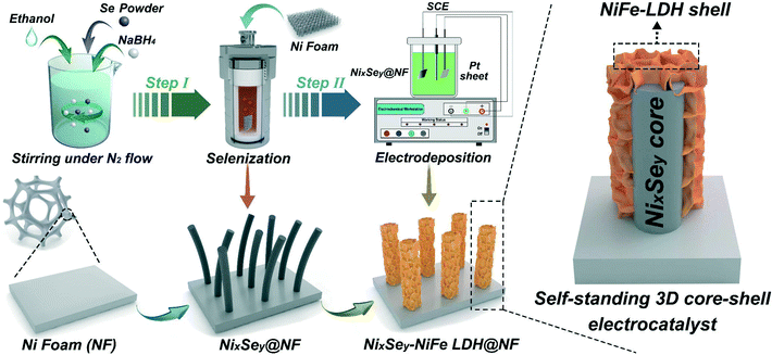
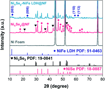
The synthetic process of the 3D hierarchical core–shell NixSey–NiFe LDH@NF electrocatalyst is briefly shown in Fig. 1, which includes the selenization process of NF and the subsequent electrodeposition. First, the grass-like NixSey nanowire arrays were in situ grown on NF by a one-step hydrothermal process utilizing NF and NaHSe as Ni and Se sources, respectively. This in situ growth pattern avoided unevenness of the surface arrays and endowed the arrays with robust mechanical strength. Then, NiFe LDH nanosheets were assembled on the NixSey nanowire arrays by a controlled electrodeposition method to construct the novel 3D hierarchical core–shell NixSey–NiFe LDH@NF electrocatalyst with a yellow surface (Fig. S1†). The NixSey nanowire arrays in situ grown on NF can work as an excellent electronic conductor for charge transfer without using polymer binders and conductive agents, and they also increase the surface area of NF, which could provide more space for growth of NiFe LDH nanosheets.X-ray diffraction (XRD) was first utilized to study the crystalline phases of the samples at each of the processing stages. As shown in Fig. 2, the three intense diffraction peaks at 44.5°, 51.8°, and 76.3° in all the samples arise from the NF substrate (JCPDS No. 04-0580). After in situ selenization of NF, the diffraction peaks at 17.7°, 31.0°, 34.1°, 38.7°, 46.5°, 48.0°, 50.4°, 53.5°, 55.1°, 56.0°, 62.7°and 64.4°can be ascribed to the (110), (300), (021), (211), (131), (410), (401), (321), (330), (012), (122) and (600) planes of NiSe, respectively (JCPDS No. 18-0887).37 Note that the additional peaks at 20.9°, 29.5°, 37.1°, 42.6° and 52.7° could be ascribed to the (101), (110), (003), (202) and (122) planes of Ni3Se2 (JCPDS No. 19-0841),38 suggesting the mixed crystalline phases of NiSe and Ni3Se2 in the NixSey@NF sample. For the NixSey–NiFe LDH@NF pattern, the weak diffraction peaks at 11.5°, 23.3°, 60.3°, and 61.3° can be indexed to the (003), (006), (110), and (113) planes of the hydrotalcite-structured NiFe LDH (JCPDS No. 51-0463).39 This confirms that the prepared sample is a composite of NixSey and NiFe LDH.
The morphologies of the obtained samples were revealed by scanning electron microscopy (SEM). The bare NF, as the substrate, shows a 3D macroporous skeleton with a smooth surface (Fig. S2 and 3a), which could facilitate rapid internal infiltration of the electrolyte and high mass loading of the electroactive material. Fig. 3b shows the low-magnification SEM image of NF after selenization, indicating that its surface is fully covered with a densely packed NixSey film. The high-magnification SEM images (Fig. 3c and d, and S4†) show the formation of disordered NixSey nanowire arrays on NF, which are like grass growing on the ground. These grass-like 1D NixSey nanowires, usually 40–80 nm in diameter and up to several micrometers in length, exhibited interconnected and twisted structures, greatly enhancing the specific surface area of the NF substrate and thus providing more space for secondary growth of NiFe LDH nanosheets. After electrodeposition of NiFe LDH, as shown in Fig. 3e and S5,† the grass-like NixSey nanowires were decorated with a large number of NiFe LDH nanosheets, which exhibited a unique 3D hierarchical core–shell nanostructure. The high magnification SEM image of NixSey–NiFe LDH@NF in Fig. 3f shows that the curved NiFe LDH nanosheets were uniformly and vertically grown around the surface of the NixSey nanowires, forming a 3D ordered network with abundant exposed edges. As a contrast, the NiFe LDH@NF was synthesized by directly electrodepositing NiFe LDH on the NF substrate, which shows typical nanosheet arrays on the surface of the NF (Fig. S3†). The elemental mapping analysis for NixSey–NiFe LDH@NF in Fig. S6 and S7† confirmed that Ni, Se, Fe, and O elements were homogeneously distributed throughout the core–shell nanoarrays and their atomic ratio was about 1![[thin space (1/6-em)]](https://www.rsc.org/images/entities/char_2009.gif) :
:![[thin space (1/6-em)]](https://www.rsc.org/images/entities/char_2009.gif) 0.3
0.3![[thin space (1/6-em)]](https://www.rsc.org/images/entities/char_2009.gif) :
:![[thin space (1/6-em)]](https://www.rsc.org/images/entities/char_2009.gif) 0.2
0.2![[thin space (1/6-em)]](https://www.rsc.org/images/entities/char_2009.gif) :
:![[thin space (1/6-em)]](https://www.rsc.org/images/entities/char_2009.gif) 2.2.
2.2.
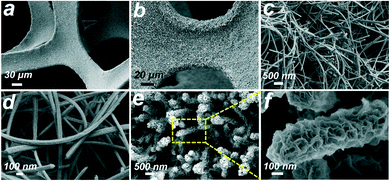 | ||
| Fig. 3 SEM images of (a) bare Ni foam (NF), (b–d) NixSey nanowire arrays on NF at low and high magnifications, and (e and f) NixSey–NiFe LDH core–shell structure arrays on NF. | ||
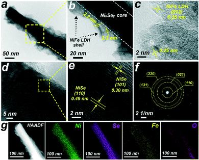
The structure of the hierarchical NixSey–NiFe LDH core–shell architecture is further shown in the transmission electron microscopy (TEM) images (Fig. 4a and b). The NiFe LDH nanosheets, homogeneously wrapping the NixSey core, are interconnected with each other and their average thickness is 2.2–2.3 nm. Further observing the edge of the nanosheets by employing high-resolution transmission electron microscopy (HRTEM) technology (Fig. 4c), we can find a typical (012) plane of NiFe LDH with an interplanar spacing of 0.25 nm.28 The HRTEM images taken from the NixSey core (Fig. 4d and e) show well-resolved lattice fringes with interplanar distances of 0.30 nm and 0.49 nm indexed to the (101) and (110) planes of NiSe, respectively.40,41 The selected-area electron-diffraction (SAED) pattern in Fig. 4f shows discrete spots indexed to the (110), (021), (131), and (330) planes of the NiSe phase,37 in accordance with the XRD results. The energy dispersive X-ray (EDX) elemental mapping images (Fig. 4g) and line scanning results (Fig. S8†) confirmed the successful synthesis of the core–shell nanostructure, which distinctly demonstrated that the Se element is in the central part while both Ni and Fe elements are homogeneously distributed throughout the whole composite.
X-ray photoelectron spectroscopy (XPS) measurements were used to determine the chemical composition and valence states of the catalysts. The full survey spectrum shown in Fig. S9† indicated the presence of Ni, Fe, O, Se, and C elements in the sample. The high-resolution spectrum of Ni 2p (Fig. 5a) was best fitted with two main spin–orbit doublets of Ni 2p3/2 and Ni 2p1/2 at 855.7 eV and 873.4 eV along with two shake-up satellite peaks (indicated as “Sat.”) at 861.0 eV and 879.4 eV, indicating that the Ni species are in the +2 oxidation state in the sample.37,39 For the spectrum of Fe 2p (Fig. 5b), two prominent peaks located at 711.8 eV and 724.9 eV are assigned to Fe 2p3/2 and Fe 2p1/2, respectively, and two satellite peaks are located at 717.6 eV and 733.2 eV, which implied the presence of the Fe3+ state.39,42 The fitting peaks of Se 3d at 53.8 eV and 54.7 eV in Fig. 5c were assigned to Se 3d5/2 and Se 3d3/2, respectively, reflecting the typical features of metal–selenium bonds.43 And the weak peak at 58.5 eV was ascribed to the Se–O bonding structures at the surface, indicating the surface oxidation state of the Se species.37 Additionally, the high-resolution O 1s spectrum (Fig. 5d) showed two characteristic peaks at 531.4 eV and 533.6 eV corresponding to the metal-hydroxyl binding and physically adsorbed H2O molecules, respectively.44,45 All these features indicated the Ni2+ and Fe3+ oxidation states on the surface of the core–shell NixSey–NiFe LDH@NF.
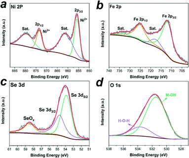 | ||
| Fig. 5 High-resolution XPS spectra of (a) Ni 2p, (b)Fe 2p, (c) Se 3d and (d) O 1s of the core–shell NixSey–NiFe LDH@NF electrode. | ||
3.2. The electrochemical performance of NixSey–NiFe LDH@NF
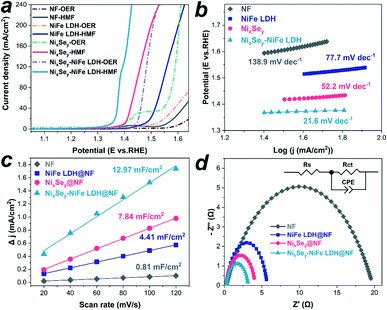
The as-synthesized catalysts were selected as the anodes to evaluate the electrochemical performance by using a typical three-electrode setup. Fig. 6a shows the linear sweep voltammetry (LSV) curves of NF, NiFe LDH@NF, NixSey@NF, and NixSey–NiFe LDH@NF electrodes in 1.0 M KOH with and without HMF. For the oxygen evolution reaction (OER) behaviors on the three electrodes in pure 1.0 M KOH electrolyte (dashed curves), NixSey–NiFe LDH@NF displayed a lower onset potential of ∼1.45 V vs. RHE than NixSey@NF (∼1.55 V vs. RHE), NiFe LDH@NF (∼1.53 V vs. RHE) and NF (∼1.58 V vs. RHE). Note that the oxidation peak at 1.45 V vs. RHE for NixSey@NF is ascribed to Ni2+ to Ni3+, and the onset potential of NixSey@NF for the OER is about 1.55 V vs. RHE.37,40 After introducing 10 mM HMF, a negative shift could be observed on the onset catalytic potentials of the NiFe LDH@NF, NixSey@NF and NixSey–NiFe LDH@NF electrodes (solid curves), indicating that HMF oxidation on these electrodes occurred with lower potential than water oxidation. Besides, the potential of NixSey–NiFe LDH@NF required to reach a current density of 50 mA cm−2 for HMF oxidation is ∼1.37 V vs. RHE, which is lower than those of NixSey@NF (∼1.42 V vs. RHE) and NiFe LDH@NF (∼1.52 V vs. RHE), suggesting the highest activity of NixSey–NiFe LDH@NF for HMF oxidation among the as-synthesized catalysts. As a control sample, the NF also showed an increase of current density in the presence of HMF at ∼1.55 V vs. RHE, indicating that HMF oxidation on the bare NF is also more favorable than the OER. In addition, we studied the influence of the electrodeposition time on the electrocatalytic activity of NixSey–NiFe LDH@NF towards HMF oxidation. The results in Fig. S11† showed that either shortened or prolonged deposition time leads to an increased potential value for HMF oxidation, indicating that NixSey–NiFe LDH@NF-60s is an optimized catalyst in this work. This was further confirmed by the SEM images presented in Fig. S10;† the loading mass of NiFe LDH on NixSey–NiFe LDH@NF-30s was too low to observe the nanosheets while that on NixSey–NiFe LDH@NF-90s was so high that the nanowire arrays were wholly covered by the nanosheets, leading to their lower activity compared with NixSey–NiFe LDH@NF-60s. Therefore, NixSey–NiFe LDH@NF-60s was chosen to be studied in the whole experiment. To investigate the kinetics for HMF oxidation, the Tafel slopes of the as-prepared electrocatalysts were obtained from the LSV curves. As shown in Fig. 6b, NixSey–NiFe LDH@NF has the smallest Tafel slope of 21.6 mV dec−1 in comparison with NixSey@NF (52.2 mV dec−1) and NiFe LDH@NF (77.7 mV dec−1) and NF (138.9 mV dec−1), suggesting the fastest HMF oxidation reaction kinetics of NixSey–NiFe LDH@NF. The activity of the four electrodes for FUR oxidation was also assessed by LSV in 1.0 M KOH electrolyte containing 20 mM FUR. As shown in Fig. S12,† NixSey–NiFe LDH@NF still exhibited the earliest onset potential (∼1.37 V vs. RHE), a rapid current increase and the smallest Tafel slope (29.8 mV dec−1) for FUR oxidation among the as-synthesized catalysts, indicating the excellent catalytic activity of NixSey–NiFe LDH@NF towards FUR oxidation.To gain further insight into the differences in the activity of NF, NiFe LDH@NF, NixSey@NF and NixSey–NiFe LDH@NF for HMF and FUR oxidation, the electrochemically active surface area (ECSA) was estimated from the double-layer capacitance (Cdl) by carrying out cyclic voltammetry (CV) tests at different scanning rates in the non-faradaic region (Fig. S13†).25 As shown in Fig. 6c, the core–shell NixSey–NiFe LDH@NF exhibited the largest Cdl of 12.97 mF cm−2, which was more than 1.6 times that of NixSey@NF (7.84 mF cm−2), 2.9 times that of NiFe LDH@NF (4.41 mF cm−2) and 16.0 times that of NF (0.81 mF cm−2), suggesting that the rational design of 3D hierarchical core–shell architectures endows NixSey–NiFe LDH@NF with increased ECSA and more exposed active sites, which could contribute to the enhanced catalytic activity. To further investigate the intrinsic activity of the electrodes towards HMF oxidation, ECSA-normalized LSV curves were also obtained as shown in Fig. S14.† The result indicates that NixSey–NiFe LDH@NF still has the best catalytic activity for HMF oxidation among the three electrodes. Moreover, the charge transfer capacity is also an important factor that influences the catalytic activity of the electrode, which was evaluated by the electrochemical impedance spectroscopy (EIS) test. As observed in the Nyquist plots with an equivalent circuit shown in Fig. 6d, NixSey–NiFe LDH@NF exhibited a much smaller charge transfer resistance (Rct) of 2.99 Ω than NixSey@NF (3.95 Ω), NiFe LDH@NF (5.58 Ω) and NF (19.90 Ω), indicating that the core–shell NixSey–NiFe LDH@NF has faster electron transport kinetics at the interface between the electrodes and electrolyte. The excellent electrical conductivity of the core–shell NixSey–NiFe LDH@NF is mainly attributed to the in situ growth pattern of the NixSey nanowire arrays on the NF, which is not only beneficial for the strong connection between the active materials and the conductive substrate, but also ensures good electrical contact for the integrated structure after electrodeposition of NiFe LDH nanosheets on the surface of NixSey.
3.3. Electrocatalytic oxidation of HMF
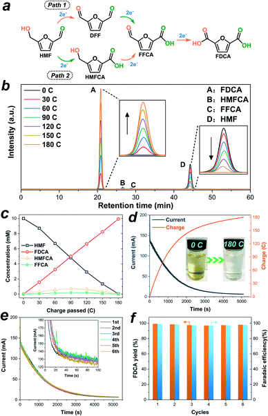
The constant potential electrolysis test of HMF was performed by using NixSey–NiFe LDH@NF as an anode in a divided cell where the anode compartment was separated from the cathode compartment by an anion exchange membrane. A potential of 1.423 V vs. RHE was applied for electrolysis based on the LSV results since high current density could contribute to HMF oxidation while water oxidation would not occur at this potential. As shown in Fig. S15 and S16,† with slight magnetic stirring, the anode cell contained 31 mL of 1.0 M KOH solution with 10 mM HMF, and the cathode cell contained 31 mL of pure 1.0 M KOH electrolyte. The half-reaction at each cell and overall reaction are summarized in the ESI.† Theoretically, the amount of charge required to completely convert the given HMF to FDCA was ∼180 C as it is a six-electron reaction. In the process of electrolysis, HPLC was employed to identify and quantify the products in the liquid samples collected from the anode cell after every 30 C of charge passed (Fig. 7b). Since two different intermediates could be produced from the selective oxidation of the aldehyde group and hydroxyl group of HMF, there are two possible pathways for electrooxidation of HMF to FDCA (Fig. 7a).12,20 Note that the concentration changes of 5-hydroxymethyl-2-furancarboxylic acid (HMFCA) and 5-formylfuran-2-carboxylic acid (FFCA) were detectable in this reaction while the concentration of 2,5-diformylfuran (DFF) was undetected (Fig. 7b), indicating that FDCA was formed following path 2 in Fig. 7a. According to the calibration curves of standard products (Fig. S17–S21†), the actual concentration value of each compound during the electrolysis is shown in Fig. 7c, suggesting that the concentration of HMF decreased while the amount of FDCA increased with increasing charge passed. Besides, after around 180 C charge was consumed (Fig. 7d), the final electrolyte solution became colorless compared to the initial yellow solution (the inset image in Fig. 7d). At the end of electrolysis, 99.6% conversion of HMF, 99.3% FDCA yield, and 98.9% FE were obtained. The stability of the NixSey–NiFe LDH@NF electrode for HMF oxidation was also investigated by carrying out six successive cycles of the constant potential electrolysis test by utilizing the same electrode. As shown in Fig. 7e, no obvious decay was observed in the current–time curves for HMF oxidation in the six continual measurements. And the yield of FDCA and the corresponding FE could be retained above 97.0% and 96.7%, respectively (Fig. 7f). The above results strongly demonstrated the high activity and durability of the NixSey–NiFe LDH@NF electrode for HMF oxidation, which make it stand out from most of the reported transition metal-based electrocatalysts (Table S1†).3.4. Electrocatalytic oxidation of FUR
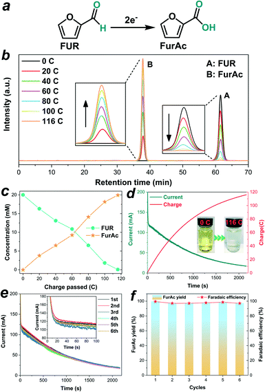
Given the excellent performance of NixSey–NiFe LDH@NF for HMF oxidation, we further explored its applicability for efficient conversion of FUR to FurAc in the same electrolyte (1.0 M KOH). The controlled potential (1.423 V vs. RHE) electrolysis test was also conducted in a three-electrode configuration with a two-compartment cell separated by an anion-exchange membrane. The relevant reactions in the anode cell and cathode cell are summarized in the ESI.† Since the oxidation of FUR to FurAc is a two-electron process (Fig. 8a), the complete conversion of 20 mM FUR (30 mL) to FurAc requires about 116 C charge based on our calculation. As shown in Fig. 8b, the concentration variations of FUR and FurAc were quantified by means of HPLC in the process of electrolysis based on the pre-established calibration curves (Fig. S22 and S23†). As increasing charge was consumed, the concentration of FUR decreased along with increasing concentration of FurAc (Fig. 8c), suggesting the continuous conversion of FUR into FurAc. After passing a charge of 116 C (Fig. 8d), the color of the electrolyte solution changed from yellow to colorless (the inset image in Fig. 8d), and nearly complete conversion of FUR (99.7%) was obtained with a 99.7% yield of FurAc and 99.5% FE. Moreover, in six successive electrolysis cycles, the current–time curves for electrolysis of FUR showed negligible degradation (Fig. 8e), and the yield of FurAc and the FE were maintained in the range of 99.7% to 97.3% and 99.5% to 97.1%, respectively (Fig. 8f), demonstrating that NixSey–NiFe LDH@NF was a promising electrocatalyst with high efficiency and robust stability compared with most of the reported electrocatalysts for FUR oxidation (Table S2†).In addition, to compare the activities of the NixSey–NiFe LDH@NF electrode and NF substrate for HMF and FUR oxidation, electrolysis tests by using the pure NF were also performed. As revealed by Fig. S24,† during four successive electrolysis cycles, only 11.7–10.9% conversion of HMF with 2.2–1.9% FDCA yield and 12.1–11.4% conversion of FUR with 2.4–2.0% FurAc yield were obtained on NF. The poor activity of NF for HMF and FUR oxidation further confirmed that the electrocatalytic performance of NixSey–NiFe LDH@NF was mainly attributed to the NixSey–NiFe LDH core–shell nanostructure.
3.5. Performance analysis of the NixSey–NiFe LDH@NF electrode for HMF and FUR electrooxidation
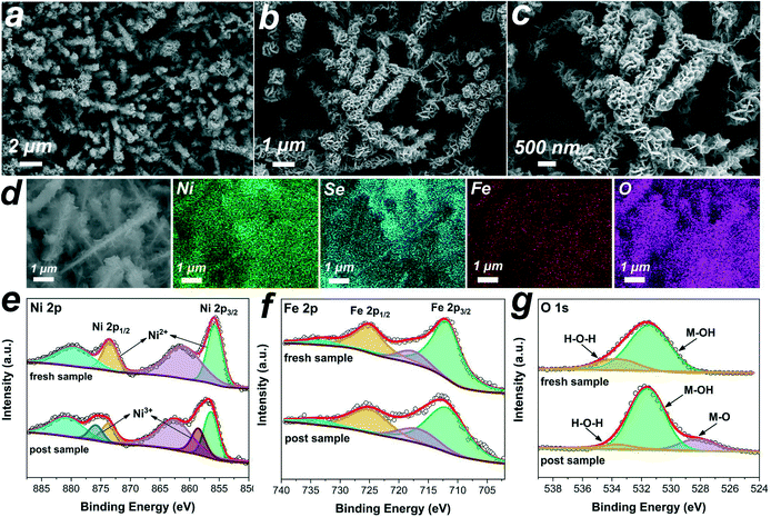
The component, morphology and electronic structure of NixSey–NiFe LDH@NF after electrolysis tests were further investigated by detailed characterization. As shown in Fig. 9a–d, the SEM images and elemental mapping results demonstrated the well-maintained nanostructure arrays with homogeneous distribution of the elements. Besides, the TEM image and the corresponding elemental mapping and line scanning results (Fig. S25†) further confirmed that the core–shell nanostructure of NixSey–NiFe LDH was preserved. Moreover, the XRD pattern (Fig. S26†) of NixSey–NiFe LDH@NF after the stability test was almost the same as that of the fresh sample, suggesting no composition and phase changes. Undoubtedly, the in situ synthesis of NixSey on the NF improved the mechanical strength of the NixSey core and further ensured the structural stability of NixSey–NiFe LDH@NF, which are crucial for the durability of the electrode during the successive electrolysis cycles. On the other hand, compared to the fresh sample of NixSey–NiFe LDH@NF, the high-resolution Ni 2p XPS spectrum of the post-electrolysis sample shows apparent increasing peaks at 858.5 eV and 875.8 eV (corresponding to Ni3+), indicating that Ni2+ was oxidized to NiOOH under alkaline conditions. Recent DFT calculation showed that the high valence state of Ni species (NiOOH) exhibited optimized adsorption configuration/energy and enhanced chemical interactions (electron transfer) with HMF.46 And previous studies also suggested that NiOOH could oxidize HMF and reduce itself to Ni(OH)2, and subsequently, the electrochemical oxidation prompted the regeneration of NiOOH from Ni(OH)2, leading to the continuous oxidation of HMF.15,20 From the Fe 2p XPS spectra of the two samples (Fig. 9f), no apparent differences were found before and after the electrolysis tests, suggesting the invariability for the Fe valence state. The O 1s XPS spectrum in Fig. 9g shows a new peak at 528.3 eV (attributed to the metal–oxygen bond) in the post-electrolysis sample, which was correlated to the formation of NiOOH species.27,47,48 It should be noted that although no obvious changes of the Fe valence state were observed, numerous studies have shown that the introduction of Fe enables high activity of Ni(OH)2/NiOOH for the OER or other small molecule oxidation.24,49–53 However, it remains unclear whether or not Fe in mixed LDH is active towards the oxidation of HMF or FUR at present. Several results showed that Fe incorporation may result in partial-charge transfer from Fe sites to activate Ni centers, thus enhancing the catalytic activity. In addition, Fe exposed on the surface of hydroxide layers contributes to an improved conductivity.52–54 Based on the previous studies, we cautiously speculated that Ni3+ acts as the dominant active site in NixSey–NiFe LDH@NF while Fe may modulate the electronic structure of Ni by inducing partial-charge transfer, thereby facilitating the oxidation of HMF and FUR.Based on the obtained experimental evidence and discussion, the superior catalytic performance of the core–shell NixSey–NiFe LDH@NF nanostructure could be mainly attributed to the following aspects (Fig. 10). Firstly, the NixSey nanowire arrays with a large surface area not only served as the physical support for thin NiFe LDH nanosheets but also ensured the fast charge carrier transfer from the conductive substrate (NF) to the surface of the shell catalytic layer. Secondly, by well wrapping around the NixSey nanowires, the NiFe-LDH nanosheets could expose more catalytically active sites, which consequently improves the ECSA of NixSey–NiFe LDH@NF. Besides, the open spaces between the neighboring composite branches could accelerate the infiltration of electrolytes as well as the adsorption/desorption of ions. Thirdly, as the dominant active species, NiOOH (from the oxidation of Ni2+) played an important role in HMF and FUR oxidation through the conversion between Ni(OH)2 and NiOOH under alkaline conditions.15 The presence of Fe in the catalyst layer might modulate the electronic structure of Ni by inducing partial-charge transfer, thus improving the catalytic activity. Finally, the binder-free nature of NixSey–NiFe LDH@NF avoided the increase of charge transfer resistance, the blockage of active sites, and the inhibition of diffusion. More importantly, the in situ growth pattern was advantageous for enhancing the mechanical strength of the NixSey nanowire core compared with epitaxial growth, preventing the collapse of the nanoarrays and agglomeration of the NiFe LDH nanosheets during electrolysis, which is key to the superior durability of NixSey–NiFe LDH@NF.
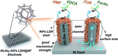 | ||
| Fig. 10 The mechanism proposed for the electrooxidation of HMF and FUR by the NixSey–NiFe LDH@NF electrode. | ||
4. Conclusions
In summary, a novel 3D hierarchical core–shell NixSey–NiFe LDH@NF electrocatalyst was successfully fabricated by assembling thin NiFe LDH nanosheets on grass-like NixSey nanowire arrays in situ grown on Ni foam for HMF and FUR electrooxidation. Our results showed that the highly conductive NixSey nanowire core ensured fast charge transfer and exhibited good mechanical strength, the thin NiFe LDH nanosheet shell with a large surface area provided abundant exposed active sites, the open structure of the hierarchical nanoarrays facilitated electrolyte diffusion, NiOOH acted as the dominant active site and the presence of Fe may improve the catalytic activity by modulating the electronic structure of Ni. Benefiting from the above advantages, the NixSey–NiFe LDH@NF core–shell catalyst exhibited superior catalytic performance for HMF and FUR oxidation by achieving considerable yields of FDCA (99.3%) and FurAc (99.7%) and high FE towards FDCA (98.9%) and FurAc (99.5%), as well as good durability retaining 96.7% FE for FDCA and 97.1% FE for FurAc after six successive electrolysis cycles. This work is expected to be useful for further rational design of structure-optimized electrocatalysts for efficient conversion of biomass-derived platform chemicals to high value-added products.Author contributions
Yan Zhong: conceptualization, methodology, validation, formal analysis, data curation, drawing and writing. Ru-Quan Ren, Jian-Bo Wang and Yi-Yi Peng: drawing and writing – review. Qiang Li and Yong-Ming Fan: methodology, supervision, funding acquisition and writing – editing. All authors reviewed the manuscript.Conflicts of interest
There are no conflicts to declare.Acknowledgements
This work was supported by the National Natural Science Foundation of China (No. 21671021), the State Key Research Project (2017YFD0600203) and Scientific and Technological Innovation Projects by Shandong Province (2019JZZY020223).Notes and references
- P. Gallezot, Chem. Soc. Rev., 2012, 41, 1538–1558 RSC.
- A. Corma, S. Iborra and A. Velty, Chem. Rev., 2007, 107, 2411–2502 CrossRef CAS.
- C. Xu, E. Paone, D. Rodriguez-Padron, R. Luque and F. Mauriello, Chem. Soc. Rev., 2020, 49, 4273–4306 RSC.
- S. Chen, R. Wojcieszak, F. Dumeignil, E. Marceau and S. Royer, Chem. Rev., 2018, 118, 11023–11117 CrossRef CAS PubMed.
- Z. Zhang and K. Deng, ACS Catal., 2015, 5, 6529–6544 CrossRef CAS.
- Z. Ren, Y. Yang, S. Wang, X. Li, H. Feng, L. Wang, Y. Li, X. Zhang and M. Wei, Appl. Catal., B, 2021, 295, 120290 CrossRef CAS.
- Y. Wang, K. Yu, D. Lei, W. Si, Y. Feng, L.-L. Lou and S. Liu, ACS Sustainable Chem. Eng., 2016, 4, 4752–4761 CrossRef CAS.
- F. Liguori, P. Barbaro and N. Calisi, ChemSusChem, 2019, 12, 2558–2563 CrossRef CAS.
- X. Xiang, B. Zhang, G. Ding, J. Cui, H. Zheng and Y. Zhu, Catal. Commun., 2016, 86, 41–45 CrossRef CAS.
- F. Kerdi, H. Ait Rass, C. Pinel, M. Besson, G. Peru, B. Leger, S. Rio, E. Monflier and A. Ponchel, Appl. Catal., A, 2015, 506, 206–219 CrossRef CAS.
- T. Pasini, M. Piccinini, M. Blosi, R. Bonelli, S. Albonetti, N. Dimitratos, J. A. Lopez-Sanchez, M. Sankar, Q. He, C. J. Kiely, G. J. Hutchings and F. Cavani, Green Chem., 2011, 13, 2091 RSC.
- H. G. Cha and K. S. Choi, Nat. Chem., 2015, 7, 328–333 CrossRef CAS.
- D. J. Chadderdon, L. Xin, J. Qi, Y. Qiu, P. Krishna, K. L. More and W. Li, Green Chem., 2014, 16, 3778–3786 RSC.
- A. M. Román, J. C. Hasse, J. W. Medlin and A. Holewinski, ACS Catal., 2019, 9, 10305–10316 CrossRef.
- B. J. Taitt, D.-H. Nam and K.-S. Choi, ACS Catal., 2018, 9, 660–670 CrossRef.
- N. Jiang, X. Liu, J. Dong, B. You, X. Liu and Y. Sun, ChemNanoMat, 2017, 3, 491–495 CrossRef CAS.
- S. R. Kubota and K. S. Choi, ChemSusChem, 2018, 11, 2138–2145 CrossRef CAS.
- M. J. Kang, H. Park, J. Jegal, S. Y. Hwang, Y. S. Kang and H. G. Cha, Appl. Catal., B, 2019, 242, 85–91 CrossRef CAS.
- Y. Lu, C.-L. Dong, Y.-C. Huang, Y. Zou, Z. Liu, Y. Liu, Y. Li, N. He, J. Shi and S. Wang, Angew. Chem., Int. Ed., 2020, 59, 19215–19221 CrossRef CAS.
- L. Gao, Z. Liu, J. Ma, L. Zhong, Z. Song, J. Xu, S. Gan, D. Han and L. Niu, Appl. Catal., B, 2020, 261, 118235 CrossRef.
- B. Liu, S. Xu, M. Zhang, X. Li, D. Decarolis, Y. Liu, Y. Wang, E. K. Gibson, C. R. A. Catlow and K. Yan, Green Chem., 2021, 23, 4034–4043 RSC.
- M. Xu and M. Wei, Adv. Funct. Mater., 2018, 28, 1802943 CrossRef.
- W.-J. Liu, L. Dang, Z. Xu, H.-Q. Yu, S. Jin and G. W. Huber, ACS Catal., 2018, 8, 5533–5541 CrossRef CAS.
- M. Zhang, Y. Liu, B. Liu, Z. Chen, H. Xu and K. Yan, ACS Catal., 2020, 10, 5179–5189 CrossRef CAS.
- S. Sirisomboonchai, S. Li, A. Yoshida, X. Li, C. Samart, A. Abudula and G. Guan, ACS Sustainable Chem. Eng., 2019, 7, 2327–2334 CrossRef CAS.
- L. Yu, H. Zhou, J. Sun, I. K. Mishra, D. Luo, F. Yu, Y. Yu, S. Chen and Z. Ren, J. Mater. Chem. A, 2018, 6, 13619–13623 RSC.
- X. Deng, X. Kang, M. Li, K. Xiang, C. Wang, Z. Guo, J. Zhang, X.-Z. Fu and J.-L. Luo, J. Mater. Chem. A, 2020, 8, 1138–1146 RSC.
- J. Zhou, L. Yu, Q. Zhu, C. Huang and Y. Yu, J. Mater. Chem. A, 2019, 7, 18118–18125 RSC.
- W. Tian, J. Zhang, H. Feng, H. Wen, X. Sun, X. Guan, D. Zheng, J. Liao, M. Yan and Y. Yao, Sustainable Energy Fuels, 2021, 5, 391–395 RSC.
- X. Yu, M. Zhang, W. Yuan and G. Shi, J. Mater. Chem. A, 2015, 3, 6921–6928 RSC.
- B. Ameri, A. M. Zardkhoshoui and S. S. Hosseiny Davarani, Sustainable Energy Fuels, 2020, 4, 5144–5155 RSC.
- X. Shi, H. Wang, P. Kannan, J. Ding, S. Ji, F. Liu, H. Gai and R. Wang, J. Mater. Chem. A, 2019, 7, 3344–3352 RSC.
- R. Yang, Y. Zhou, Y. Xing, D. Li, D. Jiang, M. Chen, W. Shi and S. Yuan, Appl. Catal., B, 2019, 253, 131–139 CrossRef CAS.
- Z. Li, M. Shao, H. An, Z. Wang, S. Xu, M. Wei, D. G. Evans and X. Duan, Chem. Sci., 2015, 6, 6624–6631 RSC.
- S. Bai, H. Chu, X. Xiang, R. Luo, J. He and A. Chen, Chem. Eng. J., 2018, 350, 148–156 CrossRef CAS.
- L. L. Feng, G. Yu, Y. Wu, G. D. Li, H. Li, Y. Sun, T. Asefa, W. Chen and X. Zou, J. Am. Chem. Soc., 2015, 137, 14023–14026 CrossRef CAS PubMed.
- C. Tang, N. Cheng, Z. Pu, W. Xing and X. Sun, Angew. Chem., Int. Ed., 2015, 54, 9351–9355 CrossRef CAS PubMed.
- Y. Zhong, B. Chang, Y. Shao, C. Xu, Y. Wu and X. Hao, ChemSusChem, 2019, 12, 2008–2014 CrossRef CAS PubMed.
- Z. Cai, X. Bu, P. Wang, W. Su, R. Wei, J. C. Ho, J. Yang and X. Wang, J. Mater. Chem. A, 2019, 7, 21722–21729 RSC.
- K. Xu, H. Ding, K. Jia, X. Lu, P. Chen, T. Zhou, H. Cheng, S. Liu, C. Wu and Y. Xie, Angew. Chem., Int. Ed., 2016, 55, 1710–1713 CrossRef CAS.
- C. Lu, Y. Yan, T. Zhai, Y. Fan and W. Zhou, Batteries Supercaps, 2020, 3, 534–540 CrossRef CAS.
- L. Yu, H. Zhou, J. Sun, F. Qin, F. Yu, J. Bao, Y. Yu, S. Chen and Z. Ren, Energy Environ. Sci., 2017, 10, 1820–1827 RSC.
- L. Quan, T. Liu, M. Yi, Q. Chen, D. Cai and H. Zhan, Electrochim. Acta, 2018, 281, 109–116 CrossRef CAS.
- C. Liu, Y. Han, L. Yao, L. Liang, J. He, Q. Hao, J. Zhang, Y. Li and H. Liu, Small, 2021, 17, e2007334 CrossRef.
- H. Sun, W. Zhang, J.-G. Li, Z. Li, X. Ao, K.-H. Xue, K. K. Ostrikov, J. Tang and C. Wang, Appl. Catal., B, 2021, 284, 119740 CrossRef CAS.
- X. Lu, K. H. Wu, B. Zhang, J. Chen, F. Li, B. J. Su, P. Yan, J. M. Chen and W. Qi, Angew. Chem., Int. Ed., 2021, 60, 14528–14535 CrossRef CAS PubMed.
- H. Zhang, X. Li, A. Hähnel, V. Naumann, C. Lin, S. Azimi, S. L. Schweizer, A. W. Maijenburg and R. B. Wehrspohn, Adv. Funct. Mater., 2018, 28, 1706847 CrossRef.
- S. Duan, Z. Liu, H. Zhuo, T. Wang, J. Liu, L. Wang, J. Liang, J. Han, Y. Huang and Q. Li, Nanoscale, 2020, 12, 21743–21749 RSC.
- P. Babar, A. Lokhande, V. Karade, I. J. Lee, D. Lee, S. Pawar and J. H. Kim, J. Colloid Interface Sci., 2019, 557, 10–17 CrossRef CAS PubMed.
- S. Klaus, Y. Cai, M. W. Louie, L. Trotochaud and A. T. Bell, J. Phys. Chem. C, 2015, 119, 7243–7254 CrossRef CAS.
- M. W. Louie and A. T. Bell, J. Am. Chem. Soc., 2013, 135, 12329–12337 CrossRef CAS.
- L. Trotochaud, S. L. Young, J. K. Ranney and S. W. Boettcher, J. Am. Chem. Soc., 2014, 136, 6744–6753 CrossRef CAS.
- S. L. Candelaria, N. M. Bedford, T. J. Woehl, N. S. Rentz, A. R. Showalter, S. Pylypenko, B. A. Bunker, S. Lee, B. Reinhart, Y. Ren, S. P. Ertem, E. B. Coughlin, N. A. Sather, J. L. Horan, A. M. Herring and L. F. Greenlee, ACS Catal., 2016, 7, 365–379 CrossRef.
- W. Ma, R. Ma, C. Wang, J. Liang, X. Liu, K. Zhou and T. Sasaki, ACS Nano, 2015, 9, 1977–1984 CrossRef CAS PubMed.
Footnote |
| † Electronic supplementary information (ESI) available. See DOI: 10.1039/d1cy01816g |
| This journal is © The Royal Society of Chemistry 2022 |

