
Revealing long-lived electron–hole migration in core–shell α/γ-Fe2O3/FCP for efficient photoelectrochemical water oxidation†
Yinyin
Li
a,
Yifan
Chen
b,
Qiannan
Wu
c,
Rui
Zhang
a,
Mingjie
Li
b,
Yanhong
Lin
a,
Dejun
Wang
a and
Tengfeng
Xie
 *a
*a
aInstitute of Physical Chemistry, College of Chemistry, Jilin University, Changchun 130012, P. R. China. E-mail: xietf@jlu.edu.cn
bDepartment of Applied Physics, The Hong Kong Polytechnic University, Hung Hom, Kowloon, Hong Kong
cState Key Laboratory of Inorganic Synthesis and Preparative Chemistry, College of Chemistry, Jilin University, Changchun 130012, P. R. China
First published on 5th November 2021
Abstract
The oxygen evolution reaction (OER) of Fe2O3 is limited by its low photocarrier separation efficiency in photoelectrochemical (PEC) water splitting. How to construct an effective photocarrier transmission route in Fe2O3 has become an important bottleneck for enhancing OER performance. Herein, we exploit a core–shell nanorod structure loaded with FeCo Prussian blue (FCP) to boost the water oxidation kinetics and charge transfer efficiency for the first time. As expected, the optimal γ-Fe2O3/α-Fe2O3 photoanode exhibits a remarkable photocurrent density of 2.4 mA cm−2 at 1.23 V vs. RHE; when a cocatalyst FCP is introduced as a hole-transport layer, it shows a photocurrent density of 3.5 mA cm−2 at 1.23 V vs. RHE, which is 8.7 times higher than that of the pure α-Fe2O3. The outstanding photochemical performance could be attributed to the highest separation efficiency. A further study on the carrier lifetime was performed and clarified that the photocarrier lifetime of the γ-Fe2O3/α-Fe2O3/FCP photoanode is prolonged (∼50.64 ps) as compared to that of the pure α-Fe2O3 photoanode (∼21.00 ps) using femtosecond time-resolved absorption spectroscopy (fs-TAS). This work successfully explains the photocatalytic water oxidation mechanism in the γ-Fe2O3/α-Fe2O3/FCP photoanode and provides an effective insight into designing a photocarrier delivery channel for the outstanding water oxidation.
1. Introduction
Photoelectrochemical (PEC) water splitting is regarded as the promising strategy to solve the energy crisis.1–3 However, the rate of the photoanode reaction is lower than that of the water reduction reaction.4,5 Therefore, improving the efficiency of the water oxidation reaction is the key to optimize the process of water splitting. In particular, α-Fe2O3 is an excellent candidate for sunlight-driven PEC water oxidation with good sunlight harvesting capability, outstanding stability and nontoxic nature.6–8 Theoretically, hematite possesses a high solar-to-hydrogen efficiency (16.8%) and a maximum photocurrent of 12.6 mA cm−2.9–11 However, the strong recombination of photo-generated carriers and the short hole-diffusion length of pure α-Fe2O3 make it have poor water oxidation ability to meet practical applications. Therefore, various remarkable strategies have been progressed to achieve effective water oxidation kinetics and charge separation and these involve ion doping (Ti4+, Ta4+, Sn4+, etc.),12–15 heterojunctions,16–18 morphology control, oxygen vacancies,19 and oxygen-evolution cocatalysts (InOOH, Fh, and CoPi).20–23Among these strategies, constructing heterojunctions is able to make use of the interfacial electric field for further enhancing spatial charge separation, such as Co3O4/Ti–Fe2O3,24 Fe2O3/CdS,25,26 Fe2O3/g-C3N4,27 and V2O5/ZnO.28 However, the interfacial charge transfer in heterojunctions is hindered due to the presence of lattice matching with different degrees between different semiconductors. As an alternative, formation of phase junctions with the same composition was found to be an effective strategy to improve efficient charge separation. Accordingly, like WO3,29 TiO230 and poly(1,4-diethynylbenzene)31 have been successfully fabricated and showed excellent charge separation efficiency. Moreover, few research studies provided an in-depth explanation on the dynamic electron and hole transfer processes using fs-TAS. Therefore, fs-TAS is necessary to study the role of phase junctions and cocatalysts in the photocatalytic OER process.
In this work, a Ti4+-doped phase junction with a hydrophilic ultrathin FeCo Prussian blue (FCP) photoanode was synthesized via a simple hydrothermal method.10,32 As expected, the optimal γ-Fe2O3/α-Fe2O3/FCP photoanode exhibits a photocurrent density of 3.5 mA cm−2 at 1.23 V vs. RHE, which is 8.7 times higher than that of pure α-Fe2O3. More importantly, the fs-TAS results demonstrate that the excellent synergies between the phase junction and FCP could not only facilitate the photoexcited hole transfer, but also maintain long-lived charge separation states (∼50.64 ps). This work provides distinct insights into designing excellent catalysts in water oxidation.
2. Experimental section
2.1 Materials
Ferric chloride hexahydrate (FeCl3·6H2O; 97.0–102%) was bought from Alfa Aesar. Potassium ferricyanide (K3[Fe(CN)6]), titanium tetrachloride (TiCl4) and sodium nitrate (NaNO3) were purchased from Sinopharm Reagent. Cobalt chloride (CoCl2) and cobalt nitrate hexahydrate (Co(NO3)2·6H2O) were bought from Shanghai Reagent. All materials were used without further purification.2.2 Synthesis of the Ti–Fe2O3 bottom layer
According to the previous report, Ti–Fe2O3 nanorod arrays could be successfully hydrothermally prepared on FTO substrates.33 The FTO glass was ultrasonically cleaned with acetone and ethanol to make its surface clean. To obtain the hydrothermal precursor solution, 0.5063 g FeCl3·6H2O and 1.0625 g NaNO3 were mixed in deionized water (100 mL) under stirring for 20 min. Subsequently, different volume amounts of TiCl4 solution (75 μL, 175 μL, and 275 μL) were added to the precursor solution. Then, the mixed aqueous solutions with different doping volumes of TiCl4 solution were transferred into a 50 mL Teflon-lined autoclave inserted with FTO, and then heated to 100 °C for 12 h in an oven. After the oven was cooled down to room temperature, the obtained Ti–FeOOH was taken out and annealed at 550 °C for two hours under an air atmosphere. On the basis of different Ti doping volumes, the samples were denoted as 75Fe2O3 (75 μL), 175Fe2O3 (175 μL) and 275Fe2O3 (275 μL). The main reactions are listed as follows:34| Fe3+ + 2H2O = FeOOH + 3H+ |
| 2FeOOH = α-Fe2O3 + H2O |
2.3 Synthesis of the γ-Fe2O3/α-Fe2O3 phase junction
2.025 g FeCl3·6H2O and 4.25 g NaNO3 were dissolved in deionized water, and the TiCl4 ethanol solution (75 μL) was mixed with the above solution (100 mL) to form a hydrothermal precursor solution. Then, a piece of the Ti–Fe2O3 bottom layer was placed into the autoclave with its conducting side facing down. The autoclave was maintained at 100 °C for 12 h and allowed to cool naturally. Subsequently, the obtained samples were washed by water several times and annealed at 550 °C for 2 h. Interestingly, several nano-sized γ-Fe2O3 formed during the second calcination process, and the conversion mechanism was evaluated using the equations below:35| α-Fe2O3 + 6H+ → 2Fe3+ + 3H2O |
| 2Fe3+ + 6NO3− → 2γ-Fe2O3 + 6NOx |
| Fe3+ + 2H2O → FeOOH + 3H+ |
| γ-Fe2O3/FeOOH → γ-Fe2O3/α-Fe2O3 + H2O |
2.4 Synthesis of the γ-Fe2O3/α-Fe2O3/FCP photoanode
The amorphous FeCo Prussian blue (FCP) cocatalyst was loaded by sequentially dipping the γ-Fe2O3/α-Fe2O3 phase junction in 0.02 M K3[Fe(CN)6] aqueous solution and 0.04 M CoCl2 aqueous solution through a method described previously.36 First, the phase junction was immersed in K3[Fe(CN)6]3− solution for 15 min and CoCl2 solution for another 15 min, alternately, followed by rinsing with deionized water and drying in air. It is necessary to repeat this step several times (two to five) to obtain the optimized photoanode. Furthermore, the obtained samples are heated at 25, 75 and 300 °C to generate the best performance.2.5 Synthesis of the γ-Fe2O3/α-Fe2O3/Co-Pi photoanode
A representative three-electrode system was used for the electrodeposition of cobalt phosphate (CoPi) on γ-Fe2O3/α-Fe2O3.22 Herein, this electrodeposition process was carried out at a constant potential of 1 V (vs. Ag/AgCl), in which the obtained γ-Fe2O3/α-Fe2O3 substrate served as the working electrode, a Pt sheet as the counter electrode, and Ag/AgCl as the reference electrode. In addition, the electrolyte was prepared by dissolving 0.1 M potassium phosphate and 0.5 mM Co(NO3)2·6H2O in water (pH = 7). In this work, the electrodeposition time was 200 s to obtain the photoanode.2.6 Structural characterization
X-ray diffraction with Cu Kα radiation (XRD, D/MAX2250 diffractometer) was applied to analyse the crystal structure from 10° to 80° at a scan rate of 10° min−1. Field-emission scanning electron microscopy (SEM; Hitachi Company) was conducted to examine the surface morphology and film thickness. High-resolution transmission electron microscopy (HR-TEM; FEI Tecnai G2 F20) and the related energy-dispersive X-ray spectrometry (EDX) were used to further analyse the elemental composition. X-ray photoelectron spectroscopy (XPS) was performed to explore the surface chemical state of elements by using the C 1s peak as a correction. A UV-vis-NIR spectrophotometer (Shimadzu UV-3600) recorded the UV-vis absorption spectrum of the samples with BaSO4 as the reference. The lock-in-based SPV measurements and TPV measurements on home-made equipment were applied to measure the separation and kinetic behaviours of photogenerated charge carriers.A Helios pump/probe setup (Ultrafast Systems LLC) could be used to perform transient absorption (TA) spectroscopy. 800 nm fs laser pulses were generated from the amplifier (Coherent Libra, 50 fs, 1 kHz). Besides, we use a 3 mm sapphire crystal to product the white light continuum probe, and use a BBO crystal with frequency doubling the 800![[thin space (1/6-em)]](https://www.rsc.org/images/entities/char_2009.gif) nm to produce 400 nm pump pulses. In addition, the diameter of the pump beam spot is 2mm, the pump power is 30 μW, and probe beam is 50 μm. The probe beam passing through the sample was collected using a UV-vis detector (CCD sensor).
nm to produce 400 nm pump pulses. In addition, the diameter of the pump beam spot is 2mm, the pump power is 30 μW, and probe beam is 50 μm. The probe beam passing through the sample was collected using a UV-vis detector (CCD sensor).
2.7 PEC measurements
The PEC measurements of the composite phase junction were evaluated in a standard three-electrode system. The working electrode, counter electrode and reference electrode are the as-synthesized phase junction, the Pt sheet, and Ag/AgCl, respectively, which make up the CHI 660E electrochemical workstation. The illuminated area was controlled to 0.283 cm2, and 1 M KOH aqueous solution (pH = 13.6) was applied as the electrolyte. A 300 W xenon lamp (Microsolar 300, Beijing Perfect light) was used to simulate AM 1.5 G illumination (100 mW cm−2).The applied potential versus Ag/AgCl was translated into potential versus RHE based on the Nernst equation:
| ERHE = EAg/AgCl + 0.059 pH + EθAg/AgCl |
Applied bias photon to current efficiency (ABPE) was calculated via the following equation:
The injection efficiency of the photoanodes was obtained through employing 0.5 M H2O2 as a hole scavenger in the 1 M KOH electrolyte, and the oxidation of H2O2 is thermodynamically and kinetically more favorable than that of water. The injection efficiency (ηinj) was determined by using the following equation:
| ηinj = JH2O/JH2O2 |
The separation efficiency of photogenerated charge carriers during the reaction was characterized by the difference values of open circuit potential between the dark and illumination conditions.
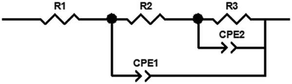
Electrochemical impedance spectroscopy (EIS) was conducted with a frequency range of 105 Hz–0.05 Hz at 1.0 V vs. RHE under illumination (100 mW cm−2) to ascertain the charge transport of the photoanode. The EIS spectrum was fitted using the ZView software according to the following fitted model:
Mott–Schottky analysis: in the M–S plot, the flat band potential of the photoelectrode is measured according to following equation:
in which C is the space charge capacitance, e is the electron charge, ε is the vacuum permittivity (8.85 × 10⁻¹² F m−1), ε0 is the relative dielectric constant of hematite (ε0 = 80), ND is the charge donor density (cm−3), E is the electrode applied potential, EFB is the flat band potential, κ is the Boltzmann constant (1.38 × 10⁻²³ J K−1) and T is the absolute temperature (in K).
3. Results and discussion
3.1 Composition and chemical state
X-ray diffraction (XRD) patterns could be measured to examine the crystalline structure of the samples (Fig. 1a). After the first hydrothermal treatment, the typical diffraction peaks located at 35.6° and 64° are indexed to the pure α-Fe2O3 (JCPDS No. 33-0664).37 After the second hydrothermal reaction, besides the characteristic peaks of α-Fe2O3, a new characteristic peak of 31.2° could be found from the enlarged XRD pattern as shown in Fig. 1b, which could be attributed to the characteristic peak of γ-Fe2O3 (JCPDS No. 39-1346).38 To further confirm the crystalline structure of γ-Fe2O3, the XRD pattern of the sample powder fabricated by the same method was obtained. The powder XRD patterns of γ-Fe2O3/α-Fe2O3 were obtained as shown in Fig. S1,† and the major diffraction peaks at 35.5° (311), 43.5° (400), 57.5° (511), and 63° (440) are in good agreement with γ-Fe2O3 (JCPDS No. 39-1346). Nevertheless, there is no evident diffraction peaks corresponding to the FeCo Prussian blue (FCP), which may result from its amorphous structure and ultrathin thickness. In order to further study the chemical states, X-ray photoelectron spectroscopy (XPS) is carried out. Fig. 1c reveals that there are two characteristic peaks at 710.5 eV and 724.1 eV, which correspond to Fe 2p3/2 and Fe 2p1/2. For pure α-Fe2O3, four characteristic peaks (709.9, 710.7, 711.5 and 713.4 eV) of Fe 2p3/2 could be fitted, while two new characteristic peaks (713.1 and 711.4 eV) belonging to γ-Fe2O3 are present. After loading FCP on the γ-Fe2O3/α-Fe2O3 sample, another peak (714.2 eV) could be assigned to an Fe–Co bond that emerged.22,39–41 In Fig. 1d, the spectrum of the O 1s region exhibits two peaks (531.6 and 529.5 eV) corresponding to the lattice oxygen (OH−) and hydroxyl oxygen (O2−).42 Moreover, the peaks located at 796.7 and the six characteristic peaks (779.9, 782.0, 783.8, 786.2, 788.4 and 790.7 eV) of γ-Fe2O3/α-Fe2O3/FCP and γ-Fe2O3/α-Fe2O3 are found to be the splitting signals of Co 2p1/2 and Co 2p3/2 (Fig. 1e), respectively.43 As illustrated in Fig. 1f, two peaks located at 464.3 eV (Ti 2p1/2) and 458.3 eV (Ti 2p3/2) for Ti 2p are observed, which can correspond to Ti4+.44 In addition, the survey scan spectrum of the γ-Fe2O3/α-Fe2O3/FCP and γ-Fe2O3/α-Fe2O3 photoanodes is shown in Fig. S2,† revealing that Fe, O, Co, and Ti are all detected. Moreover, the Raman spectra of γ-Fe2O3/α-Fe2O3 and α-Fe2O3 were measured as shown in Fig. S3,† and this also confirms the existence of γ-Fe2O3.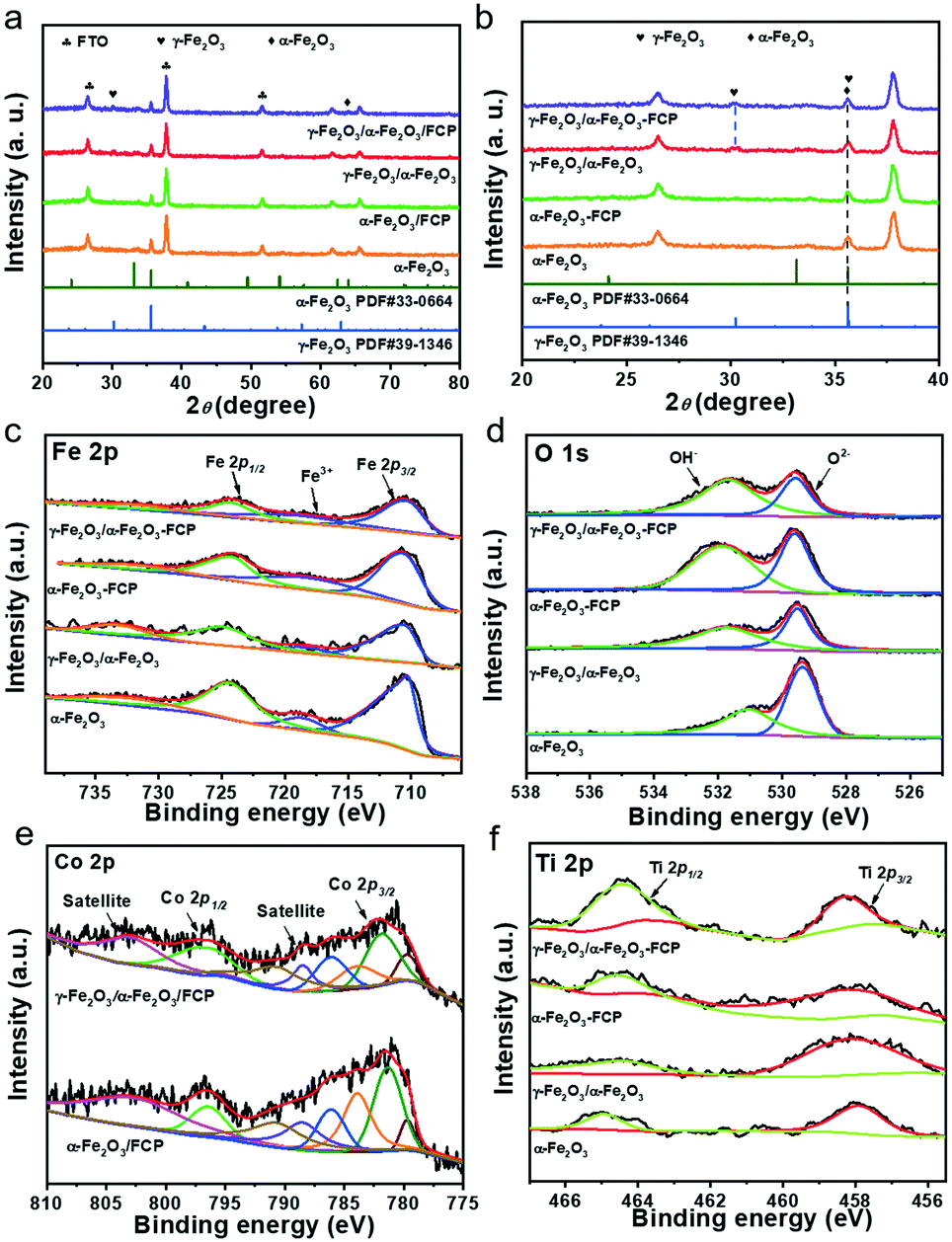 | ||
| Fig. 1 (a) XRD patterns of the α-Fe2O3-based photoanodes; (b) enlarged XRD patterns in the range of 20–40°. XPS spectra of the α-Fe2O3-based photoanodes: Fe 2p (c); O 1s (d); Co 2p (e); Ti 2p (f). | ||
Fig. 2a shows the schematic of the overall hydrothermal procedure of the core–shell structure. To study the morphologies of the as-prepared samples, the top-view and cross-sectional images from scanning electron microscopy (SEM) are shown in Fig. 2b and c; herein, the γ-Fe2O3/α-Fe2O3/FCP sample is made up of uniform and homogeneous nanorod arrays. There is no change in the surface morphology between γ-Fe2O3/α-Fe2O3 and the pristine α-Fe2O3 (Fig. S4).† Moreover, the high-resolution transmission electron microscopy (HR-TEM) image clearly reveals that the obtained photoanodes possess a core–shell structure, and the amorphous FCP was simultaneously formed on their surfaces (Fig. 2d). The typical lattice fringes of the phase junction (0.24 nm) belong to the (110) plane of γ-Fe2O3, while another lattice fringe (0.22 nm) could correspond to the (113) plane of α-Fe2O3 (Fig. 2e).45 In addition, the Fe, O, Co and Ti elements in γ-Fe2O3/α-Fe2O3/FCP demonstrate that the FCP nanoparticles were uniformly dispersed in the γ-Fe2O3/α-Fe2O3 sample (Fig. 2f).
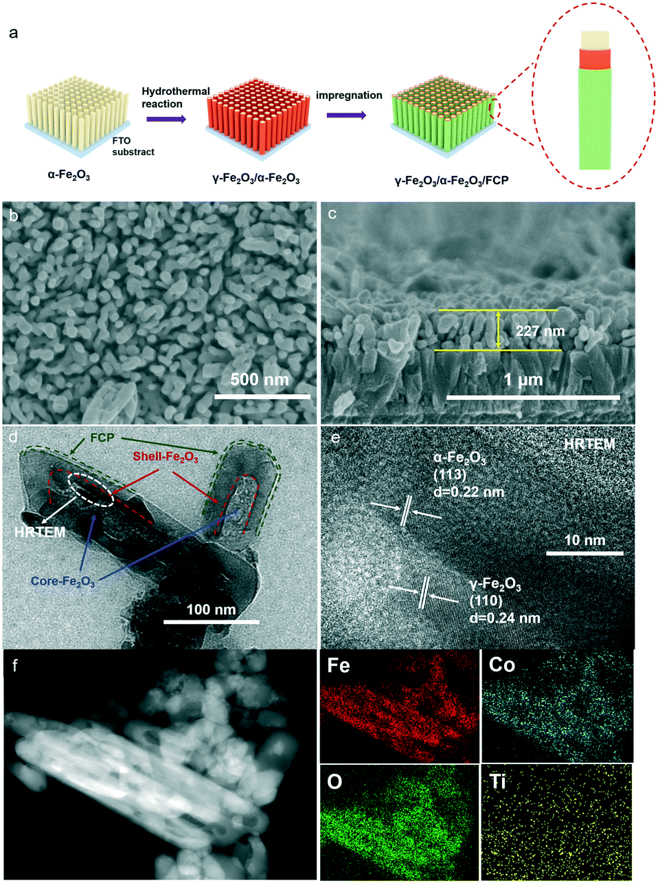 | ||
| Fig. 2 (a) Fabrication diagram of the nanoarrays. (b) Superficial SEM image of γ-Fe2O3/α-Fe2O3/FCP. (c) Cross-sectional image of γ-Fe2O3/α-Fe2O3/FCP. (d) Magnified image of the core–shell structure of γ-Fe2O3/α-Fe2O3/FCP. (e) HR-TEM image of γ-Fe2O3/α-Fe2O3/FCP. (f) EDX elemental mapping of γ-Fe2O3/α-Fe2O3/FCP. | ||
3.2 The synergistic effect of the phase junction and FCP in PEC water-oxidation performance
The PEC measurement is a basic strategy to systematically investigate the performance of the photoanode with the solar simulated light illumination (AM 1.5 G, 100 mW cm−2). Firstly, to verify the photocatalysis potential, the photoanodes are optimized by adjusting different Ti-doping volumes in the Fe2O3 bottom layer. As shown in Fig. S5a,† the core–shell phase junction with the 175 μL doping volume of Ti4+ in the Fe2O3 bottom layer possesses the best photocurrent response (denoted as γ-Fe2O3/α-Fe2O3). In addition, the ABPE and IPCE measurements (Fig. S5b and c†) also indicate that this phase junction exhibits the highest IPCE value (58% at 390 nm) and ABPE value (0.169%). Particularly, when modifying with the ultrathin FCP layer (Fig. 3a), the γ-Fe2O3/α-Fe2O3/FCP sample achieves excellent PEC performance; it is worth noting that the reaction time and temperature of FCP were optimized to obtain the optimal sample (Fig. S6);† the optimized current could reach 3.5 mA cm−2 at 1.23 V vs. RHE, which is 8.5 times greater than that of pure α-Fe2O3. And the sample exhibits a ∼90 mV cathodic shift of the onset potential (Fig. S7†). In addition, FCP has a better photocatalytic performance than cobalt phosphate (CoPi) (Fig. S8†). The above analysis implies that the synergistic effect of the phase junction and FCP could optimize the performance in water oxidation. In order to comprehensively understand the role of the phase junction and FCP in improving the PEC performance, transient photocurrent response measurements under chopped light with a frequency of 0.25 Hz are employed (Fig. 3b). It shows that the photocurrent densities follow the trend γ-Fe2O3/α-Fe2O3/FCP > γ-Fe2O3/α-Fe2O3 > α-Fe2O3/FCP > α-Fe2O3, suggesting that the surface decoration of FCP and γ-Fe2O3 is unable to improve the water oxidation capacity. Further, chronoamperometric measurements based on i–t curves at 1.23 V vs. RHE are also performed (Fig. 3c), which is also consistent with the LSV results. Meanwhile, γ-Fe2O3/α-Fe2O3/FCP shows the highest ABPE as compared to others, and its value could reach up to 0.38% at 1.02 VRHE (Fig. 3d). And the γ-Fe2O3/α-Fe2O3/FCP sample exhibits the highest IPCE value of 87% at 390 nm (Fig. 3e). Moreover, after 2 h photostability measurements, the γ-Fe2O3/α-Fe2O3/FCP and γ-Fe2O3/α-Fe2O3 samples could maintain about 94% and 97% of the initial photocurrent density (Fig. 3f), respectively. Interestingly, the contact angle of γ-Fe2O3/α-Fe2O3/FCP and α-Fe2O3 (Fig. 3f) was also measured to elucidate the liquid surface adhesion. Herein, a relatively smaller contact angle is obtained for γ-Fe2O3/α-Fe2O3/FCP, indicating that γ-Fe2O3/α-Fe2O3/FCP possesses the outstanding hydrophilic properties in the observed excellent PEC performance.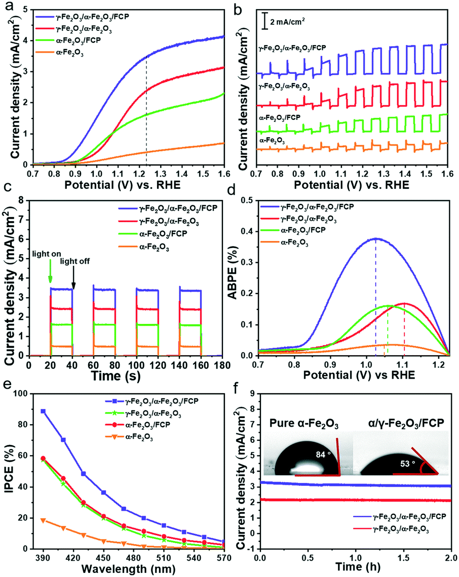 | ||
| Fig. 3 (a) Current density–potential curves. (b) LSV curves under chopped light. (c) i–t curves at 1.23 VRHE. (d) ABPE spectra. (e) IPCE plots at 1.23 V vs. RHE. (f) Results of the PEC OER stability test at 1.23 V vs. RHE in KOH electrolyte. The inset shows the water contact angle under ambient conditions. | ||
Typically, three key factors in developing suitable photocatalysts could be attributed to solar light harvesting, photocarrier separation and injection efficiency.46,47 First, the UV-vis diffuse reflectance spectra of the photoanode are measured (Fig. S9a),† and the light absorption wavelength edge of all the samples is around 600 nm. The bandgaps (Eg) of α-Fe2O3 could be estimated to be 2.11 eV based on the corresponding Tauc analysis (Fig. S9b).† These results indicate that both phase junction and FCP have no significant effect on the absorption properties. Consequently, it is reasonable to deduce that the enhanced charge separation and injection efficiency are the main reasons for the enhanced PEC performance.
Based on the above analysis and assumptions, open-circuit photovoltage (OCP) measurements are carried out to verify the effects on the behaviour of generated charges (Fig. 4a). In this work, the open circuit voltage (OCP) is the difference value between the open circuit voltage in the dark state (Vdark) and the open circuit voltage under the light state (Vlight). The open circuit voltages in the dark state and the light state used here are both stable voltage values. The γ-Fe2O3/α-Fe2O3/FCP sample exhibits the highest OCP values, suggesting that the composite photoanode could offer an additional intrinsic built-in electric field to boost the driving force of charge separation. Besides, the injection efficiency of the photoanodes in 1 M KOH with or without 0.5 M H2O2 could be used to estimate the charge transfer efficiency at the interface between the phase junction and FCP (Fig. 4b). The hole injection efficiency is significantly improved when the phase junction and FCP are introduced. Meanwhile, M–S plot analysis is conducted to obtain underlying information about the charge transfer process, in which a much flatter slope for γ-Fe2O3/α-Fe2O3/FCP could be achieved as shown in Fig. 4c. Particularly, the ND values of α-Fe2O3 and γ-Fe2O3/α-Fe2O3/FCP are 4 × 1019 cm−3 and 1.15 × 1020 cm−3, respectively (see the inset in Fig. 4c). This result implies a substantially higher charge carrier density, which leads to the effective charge separation and transfer. Moreover, we investigate the driving force at the interfacial electric field between α-Fe2O3 and the FCP through the WF measurements (Fig. S10),† which directly reveals the contact potential difference (CPD) between the sample and the Au probe. The WF values are calculated based on the following equation:
| Φsample = ΦAu + eCPD (ΦAu = 4.8 eV) |
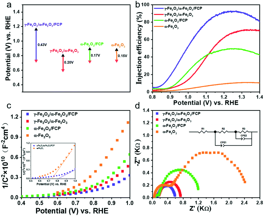 | ||
| Fig. 4 (a) Open circuit potentials (OCPs) in 1 M KOH electrolyte. (b) Injection efficiencies. (c) M–S plots. The inset shows the enlarged Mott–Schottky curves. (d) Nyquist plots at 1.0 V vs. RHE. | ||
Herein, the WF values of α-Fe2O3 and the FCP were determined to be 4.71 and 5.07 eV, respectively. The results indicated that the Fermi level of α-Fe2O3 is higher than that of FCP, and the free electrons would transfer from α-Fe2O3 to FCP until the Fermi level is aligned when FCP is deposited on α-Fe2O3. It has been clearly demonstrated earlier that the interfacial electric field is oriented from α-Fe2O3 to FCP, which could facilitate the hole transfer from α-Fe2O3 to FCP.
To further illustrate the impressive role of the phase junction and FCP in the charge transfer process, electrochemical impedance spectroscopy (EIS) analysis was conducted. It should be noted that the small and the large semicircle are relative to the charge transfer resistance (R2) at the solid/solid interface and the charge injection resistance (R3) at the photoanode/electrolyte interface, respectively.48,49 As shown in Fig. 4d, the typical EIS Nyquist plots of the obtained four photoanodes are fitted using the equivalent circuit model. Their results are listed in Table S1† and the equivalent circuit is shown in Fig. S11.† It is worth mentioning that the charge transfer resistance (R2) at the interface of γ-Fe2O3 and α-Fe2O3 dramatically lowered, which suggests that the phase junction is expected to accelerate the charge separation. It is apparent that a drastically decreased radius of γ-Fe2O3/α-Fe2O3/FCP is found relative to γ-Fe2O3/α-Fe2O3, which means that the R3 of photogenerated holes is dramatically reduced due to the superior catalytic properties of FCP.
3.3 The charge carrier dynamics of the α-Fe2O3-based photoanodes
To deeply understand the transfer and separation of photogenerated charges, a surface/transient photovoltage (SPV/TPV) test is conducted (introduction of instruments in the ESI†). Theoretically, the SPV signal could be used to deduce the separation efficiency of the photocatalyst. And the stronger signal indicates better separation efficiency.50–53 As shown in Fig. 5a, pure α-Fe2O3 exhibits a relatively weak SPV signal while γ-Fe2O3/α-Fe2O3/FCP shows the strongest SPV values. Besides, the conventional TPV signal of the phase junctions under 532 nm laser pulse is implemented to confirm the transfer processes of photogenerated charge carriers. The increasing signal suggests the outstanding separation efficiency. As shown in Fig. 5b, the γ-Fe2O3/α-Fe2O3/FCP photoanode prolongs the lifetime of photogenerated charges and effectively suppresses charge recombination. Moreover, we employed photoluminescence (PL) spectroscopy to further explore the charge recombination behaviors. The peaks at 633 nm (Fig. 5c) indicated that the synergistic effect of FCP and the core–shell phase junction was effective in suppressing the charge recombination. In addition, time-resolved photoluminescence (TRPL) was conducted to further understand the role of FCP and the phase junction in the dynamics of charge carriers. And the PL decay spectrum (Fig. 5d) was fitted using the biexponential function for obtaining the first fast decay and the later slow decay (inset in Fig. 5d). Herein, the fast lifetime (τ1) of the samples decreased from 0.42 to 0.32 ns when γ-Fe2O3/α-Fe2O3/FCP was formed, and the slow lifetime (τ2) of the γ-Fe2O3/α-Fe2O3/FCP photoanode drastically reduced from 4.96 to 4.52 ns; double-exponential fitting is suitable for the PL decay curve probed at 485 nm (Fig. S12).† These results fully explained that the introduction of FCP and the phase junction could effectively improve the charge separation efficiency.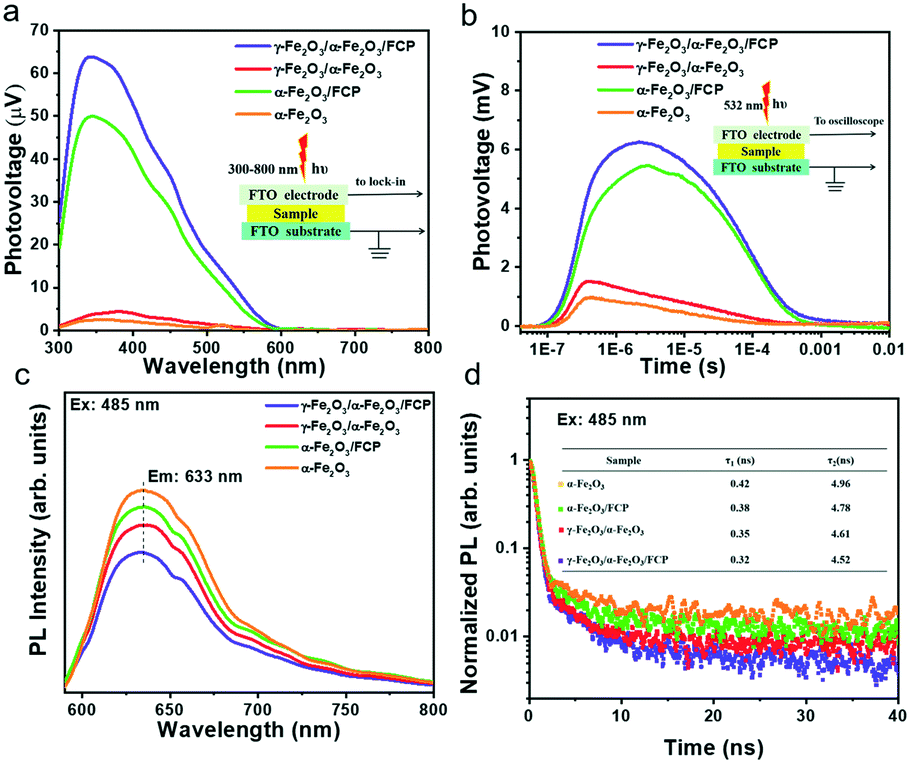 | ||
| Fig. 5 (a) SPV signal. The inset shows the schematic of the SPV measurements. (b) TPV signal from front side illumination. The inset shows the schematic of the TPV measurements. (c) Steady-state photoluminescence (PL) spectra at the excitation wavelength of 485 nm produced by a xenon lamp. (d) Results of time-resolved photoluminescence (TRPL) excited by a 485 nm pumped pulsed laser. | ||
Femtosecond time-resolved transient absorption spectroscopy (fs-TAS) is applied to investigate the electron–hole separation efficiency and understand the kinetics process of oxygen production on the PEC performance. Herein, fs-TAS is used to track the real-time photogenerated hole dynamics under 400 nm excitation.13,54–57 All samples obtained a broad negative absorption band as shown in Fig. 6a–d, due to the presence of the state filling of photobleaching and the stimulated emission. Compared with pure α-Fe2O3, the more intensive negative signal of γ-Fe2O3/α-Fe2O3 suggests that more photogenerated holes in the phase junction could be extracted from bulk. Moreover, the further improvement of the signal is mainly due to the ultrathin catalyst FCP; it is obvious that the FCP has a positive effect on the PEC performance. In addition, as shown in Fig. 6e–i, double-exponential fitting is suitable for the TAS decay curve probed at 585 nm in order to study the decay kinetics of photo-generated holes, and the related parameters are shown in Table S2.† Theoretically, the short lifetime (τ1) and long lifetime (τ2) components could be used to estimate the recombination degree. The prolonged lifetimes of the γ-Fe2O3/α-Fe2O3 and γ-Fe2O3/α-Fe2O3/FCP photoanodes are largely increased (τ1: 0.94 ± 0.014 ps; τ2: 33.45 ± 0.50 ps and τ1: 1.31 ± 0.029 ps; τ2: 50.64 ± 0.78 ps, respectively), as compared to that of pure α-Fe2O3 (τ1: 0.81 ± 0.019 ps; τ2: 21.00 ± 0.58 ps). As we know, during the PEC water splitting reaction, more longer-lived photogenerated holes on the surface are more beneficial for the PEC water splitting reaction, and the lifetimes of the different photoanodes follow the order γ-Fe2O3/α-Fe2O3/FCP > γ-Fe2O3/α-Fe2O3 > α-Fe2O3/FCP > α-Fe2O3, which is consistent with the results of the PEC performance. In addition, the pseudocolor TA plots (Fig. S13†) of the α-Fe2O3-based photoanodes indicate that the active ultralong lived charge separation state facilitates the water oxidation.
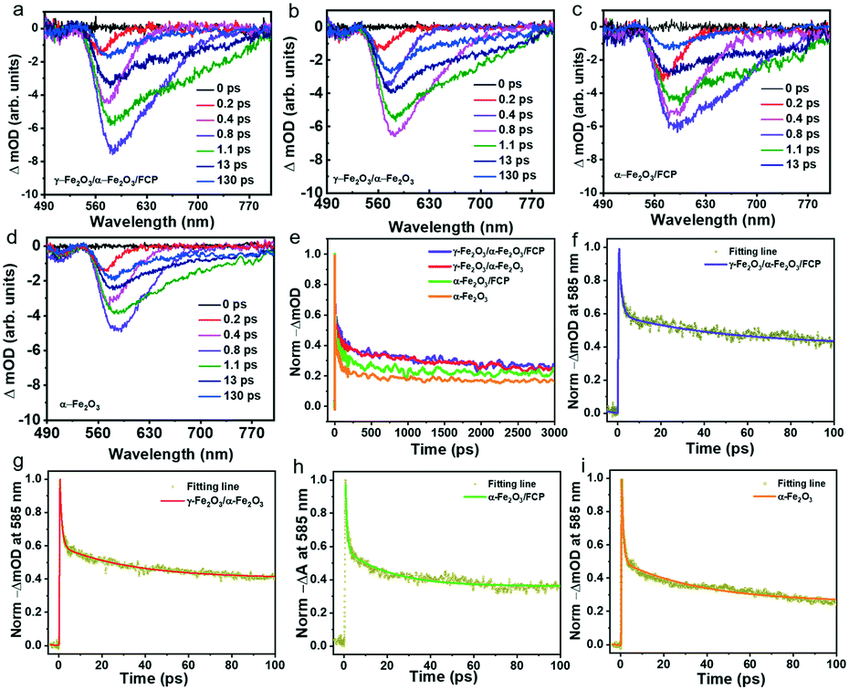 | ||
| Fig. 6 TAS spectra of a) γ-Fe2O3/α-Fe2O3/FCP, b) γ-Fe2O3/α-Fe2O3, c) α-Fe2O3/FCP, and d) α-Fe2O3 pumped by a 400 nm femtosecond laser. e) Time profiles of the normalized TAS at 585 nm. Experimental decay kinetics fitted at 585 nm: f) γ-Fe2O3/α-Fe2O3/FCP, g) γ-Fe2O3/α-Fe2O3, h) α-Fe2O3/FCP and i) α-Fe2O3. | ||
According to the above conclusion, Scheme 1 shows the schematic band diagram of the γ-Fe2O3/α-Fe2O3/FCP composite photoanode for water oxidation. In this system, benefitting from the enhanced charge separation, the holes of γ-Fe2O3 could timely transfer to α-Fe2O3 at the γ-Fe2O3/α-Fe2O3 interface. Meanwhile, the holes on α-Fe2O3 quickly captured by FCP could further participate in the water splitting reaction.
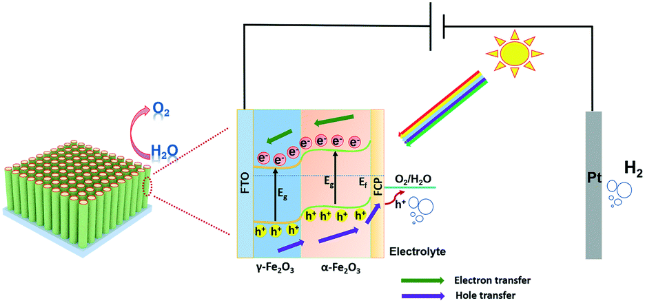 | ||
| Scheme 1 The schematic band diagram illustrating the γ-Fe2O3/α-Fe2O3/FCP photoanode architecture with directions of charge separation and transportation. | ||
4. Conclusions
In this study, it is demonstrated that both phase junction and FCP in γ-Fe2O3/α-Fe2O3/FCP could optimize the kinetics in water oxidation and improve the interfacial charge transfer for PEC water splitting. As a result, the optimal γ/α-Fe2O3/FCP composite photoanode exhibits the fast surface kinetics of α-Fe2O3 and a considerably negative onset potential, achieving a remarkable photocurrent density of up to 3.5 mA cm−2 at 1.23 V vs. RHE, which is 8.7 times higher than that of pure α-Fe2O3. The excellent bi-functional effects originate from the rapid interfacial hole injection and long-lived charge separation states (∼50.64 ps) as investigated by fs-TAS, indicating that the core–shell nanorod structure loaded with FeCo Prussian blue (FCP) could boost the water oxidation kinetics and charge transfer efficiency. This work provides an effective insight into designing an outstanding water splitting photoanode.Conflicts of interest
There are no conflicts to declare.Acknowledgements
We are grateful to the National Natural Science Foundation of China (No. 21773086, 21872063).Notes and references
- D. Zhang, W. He, J. Ye, X. Gao, D. Wang and J. Song, Small, 2021, 2005149 CrossRef CAS.
- Y. Xu, Z. Zhang, C. Qiu, S. Chen, X. Ling and C. Su, ChemSusChem, 2021, 14, 582–589 CrossRef CAS PubMed.
- X. Ren, Y. Ji, Y. Zhai, N. Yuan, J. Ding, Y. Li, J. Yan and S. F. Liu, J. Energy Chem., 2021, 60, 512–521 CrossRef.
- W. Fu, X. Guan, Y. Si and M. Liu, Chem. Eng. J., 2021, 410, 128391 CrossRef CAS.
- S. Lin, H. Ren, Z. Wu, L. Sun, X.-G. Zhang, Y.-M. Lin, K. H. L. Zhang, C.-J. Lin, Z.-Q. Tian and J.-F. Li, J. Energy Chem., 2021, 59, 721–729 CrossRef.
- H. Li, M. Yin, X. Li and R. Mo, ChemSusChem, 2021, 1–11 Search PubMed.
- Y. Fan, X. Ning, Q. Zhang, H. Zhao, J. Liu, P. Du and X. Lu, ChemSusChem, 2021, 14, 1414–1422 CrossRef CAS PubMed.
- C. Li, T. Wang, Z. Luo, S. Liu and J. Gong, Small, 2016, 12, 3415–3422 CrossRef CAS.
- T. H. Jeon, G.-h. Moon, H. Park and W. Choi, Nano Energy, 2017, 39, 211–218 CrossRef CAS.
- F. Feng, C. Li, J. Jian, F. Li, Y. Xu, H. Wang and L. Jia, J. Power Sources, 2020, 449, 227473 CrossRef CAS.
- T. Jiao, C. Lu, D. Zhang, K. Feng, S. Wang, Z. Kang and J. Zhong, Appl. Catal., B, 2020, 269, 118768 CrossRef CAS.
- C. Li, Z. Luo, T. Wang and J. Gong, Adv. Mater., 2018, 30, e1707502 CrossRef PubMed.
- H. Zhang, D. Li, W. J. Byun, X. Wang, T. J. Shin, H. Y. Jeong, H. Han, C. Li and J. S. Lee, Nat. Commun., 2020, 11, 4622 CrossRef.
- M. Li, Y. Yang, Y. Ling, W. Qiu, F. Wang, T. Liu, Y. Song, X. Liu, P. Fang, Y. Tong and Y. Li, Nano Lett., 2017, 17, 2490–2495 CrossRef CAS.
- Y. L. Tong, B. Q. Chi, D. L. Qi and W. Zhang, RSC Adv., 2021, 11, 1233–1240 RSC.
- R. Kant, S. Pathak and V. Dutta, Sol. Energy Mater. Sol. Cells, 2018, 178, 38–45 CrossRef CAS.
- A. Helal, F. A. Harraz, A. A. Ismail, T. M. Sami and I. A. Ibrahim, Appl. Catal., B, 2017, 213, 18–27 CrossRef CAS.
- P. I. Kyesmen, N. Nombona and M. Diale, J. Alloys Compd., 2021, 863, 158724 CrossRef CAS.
- Y. Makimizu, N. T. Nguyen, J. Tucek, H. J. Ahn, J. Yoo, M. Poornajar, I. Hwang, S. Kment and P. Schmuki, Chemistry, 2020, 26, 2685–2692 CrossRef CAS.
- S. Zhang, P. Shangguan, S. Tong, Z. Zhang and W. Leng, J. Phys. Chem. C, 2019, 123, 24352–24361 CrossRef CAS.
- Q. Bu, S. Li, Q. Wu, L. Bi, Y. Lin, D. Wang, X. Zou and T. Xie, ChemSusChem, 2018, 11, 3486–3494 CrossRef CAS.
- Q. Bu, S. Li, K. Zhang, Y. Lin, D. Wang, X. Zou and T. Xie, ACS Sustainable Chem. Eng., 2019, 7, 10971–10978 CrossRef CAS.
- Z. Wang, J. Rong, J. Lv, R. Chong, L. Zhang, L. Wang, Z. Chang and X. Wang, J. Energy Chem., 2021, 56, 152–161 CrossRef.
- S.-S. Yi, B.-R. Wulan, J.-M. Yan and Q. Jiang, Adv. Funct. Mater., 2019, 29, 1801902 CrossRef.
- R. Shen, L. Zhang, X. Chen, M. Jaroniec, N. Li and X. Li, Appl. Catal., B, 2020, 266, 118619 CrossRef CAS.
- Y. Li, Q. Wu, Q. Bu, K. Zhang, Y. Lin, D. Wang, X. Zou and T. Xie, Chin. J. Catal., 2021, 42, 762–771 CrossRef CAS.
- R. Zhang, L. Bi, D. Wang, Y. Lin, X. Zou and T. Xie, Catal. Commun., 2020, 142, 106028 CrossRef CAS.
- T.-F. Hou, M. A. Johar, R. Boppella, M. A. Hassan, S. J. Patil, S.-W. Ryu and D.-W. Lee, J. Energy Chem., 2020, 49, 262–274 CrossRef.
- Y. Li, Z. Tang, J. Zhang and Z. Zhang, Appl. Catal., B, 2017, 207, 207–217 CrossRef CAS.
- H. Zhang, L. Ma, J. Ming, B. Liu, Y. Zhao, Y. Hou, Z. Ding, C. Xu, Z. Zhang and J. Long, Appl. Catal., B, 2019, 243, 481–489 CrossRef CAS.
- H. Sun, C. Neumann, T. Zhang, M. Loffler, A. Wolf, Y. Hou, A. Turchanin, J. Zhang and X. Feng, Adv. Mater., 2019, 31, e1900961 CrossRef.
- J. H. Kim, J. H. Kim, J. H. Kim, Y. K. Kim and J. S. Lee, Sol. RRL, 2019, 4, 1900328 CrossRef.
- Q. Wu, Q. Bu, S. Li, Y. Lin, X. Zou, D. Wang and T. Xie, J. Alloys Compd., 2019, 803, 1105–1111 CrossRef CAS.
- D. Chen, Z. Liu and S. Zhang, Appl. Catal., B, 2020, 265, 118580 CrossRef CAS.
- D. Cao, H. Li, L. Pan, J. Li, X. Wang, P. Jing, X. Cheng, W. Wang, J. Wang and Q. Liu, Sci. Rep., 2016, 6, 32360 CrossRef CAS.
- B. Moss, F. S. Hegner, S. Corby, S. Selim, L. Francàs, N. López, S. Giménez, J.-R. Galán-Mascarós and J. R. Durrant, ACS Energy Lett., 2018, 4, 337–342 CrossRef.
- Y. Zhang, J. He, Q. Yang, H. Zhu, Q. Wang, Q. Xue and L. Yu, J. Power Sources, 2019, 440, 227120 CrossRef CAS.
- C. Yang, J. Zhang, X. Zhu, Y. Liu, Y. Chen and C. Wang, Appl. Surf. Sci., 2020, 529, 147060 CrossRef CAS.
- H. Lan, A. Wei, H. Zheng, X. Sun and J. Zhong, Nanoscale, 2018, 10, 7033–7039 RSC.
- M. C. Biesinger, B. P. Payne, A. P. Grosvenor, L. W. M. Lau, A. R. Gerson and R. S. C. Smart, Appl. Surf. Sci., 2011, 257, 2717–2730 CrossRef CAS.
- J. L. Ortiz-Quinonez, U. Pal and M. S. Villanueva, ACS Omega, 2018, 3, 14986–15001 CrossRef CAS PubMed.
- B. Sun, W. Zhou, H. Li, L. Ren, P. Qiao, F. Xiao, L. Wang, B. Jiang and H. Fu, Appl. Catal., B, 2018, 221, 235–242 CrossRef CAS.
- K. Fan, H. Chen, B. He and J. Yu, Chem. Eng. J., 2020, 392, 123744 CrossRef CAS.
- S. Li, Q. Zhao, D. Meng, D. Wang and T. Xie, J. Mater. Chem. A, 2016, 4, 16661–16669 RSC.
- Y. Jin, L. Dang, H. Zhang, C. Song, Q. Lu and F. Gao, Chem. Eng. J., 2017, 326, 292–297 CrossRef CAS.
- A. Govind Rajan, J. M. P. Martirez and E. A. Carter, ACS Catal., 2020, 10, 11177–11234 CrossRef CAS.
- S. Cao, J. Low, J. Yu and M. Jaroniec, Adv. Mater., 2015, 27, 2150–2176 CrossRef CAS PubMed.
- B. Zhang, L. Chou and Y. Bi, Appl. Catal., B, 2020, 262, 258–265 Search PubMed.
- C. Feng, Q. Zhou, B. Zheng, X. Cheng, Y. Zhang and Y. Bi, J. Mater. Chem. A, 2019, 7, 22274–22278 RSC.
- T. Jiang, T. Xie, W. Yang, L. Chen, H. Fan and D. Wang, J. Phys. Chem. C, 2013, 117, 4619–4624 CrossRef CAS.
- T. Jiang, T. Xie, L. Chen, Z. Fu and D. Wang, Nanoscale, 2013, 5, 2938–2944 RSC.
- L. Bi, X. Gao, Z. Ma, L. Zhang, D. Wang and T. Xie, ChemCatChem, 2017, 9, 3779–3785 CrossRef CAS.
- Y. Li, Q. Wu, K. Zhang, B. Hu, Y. Lin, D. Wang and T. Xie, Chem. Res. Chin. Univ., 2020, 36, 1059–1067 CrossRef CAS.
- W. Wang, Y. Tao, L. Du, Z. Wei, Z. Yan, W. K. Chan, Z. Lian, R. Zhu, D. L. Phillips and G. Li, Appl. Catal., B, 2021, 282, 119568 CrossRef CAS.
- F. Liu, R. Shi, Z. Wang, Y. Weng, C. M. Che and Y. Chen, Angew. Chem., Int. Ed., 2019, 58, 11791–11795 CrossRef CAS.
- M. Sachs, J. S. Park, E. Pastor, A. Kafizas, A. A. Wilson, L. Francas, S. Gul, M. Ling, C. Blackman, J. Yano, A. Walsh and J. R. Durrant, Chem. Sci., 2019, 10, 5667–5677 RSC.
- Y. Li, Q. Wu, Y. Chen, R. Zhang, C. Li, K. Zhang, M. Li, Y. Lin, D. Wang, X. Zou and T. Xie, Appl. Catal., B, 2021, 290, 120058 CrossRef CAS.
Footnote |
| † Electronic supplementary information (ESI) available. See DOI: 10.1039/d1cy01628h |
| This journal is © The Royal Society of Chemistry 2022 |