Mass production of thermally stable Pt single-atom catalysts for the catalytic oxidation of sulfur dioxide
Wang
Jianchen
,
Kang
Yong
 * and
Fangkuan
Sun
School of Chemical Engineering and Technology, Tianjin University, Tianjin 300350, China. E-mail: ykang@tju.edu.cn
First published on 5th November 2021
Abstract
Owing to the 100% atom utilization and the potential in bridging the gap between homogeneous catalysis and heterogeneous catalysis, single-atom catalysts (SACs) have doubtlessly obtained broad attention from both academia and industry. However, the thermal stability and the simple and scalable production of single-atom catalysts remain an arduous project for their applications from laboratory curiosity to a practical solution of industrial chemical processes. Here, we report the synthesis of Pt SACs from commercial PtO2 powders by calcining a physical mixture of PtO2 aggregates with α-Fe2O3 or Fe-containing supports at high temperature. The thorough dispersion of PtO2 powders into isolated Pt single atoms is attributed to the anti-Ostwald ripening process promoted by a strong covalent metal–support interaction between Pt and Fe via high-temperature calcination. The as-prepared pellet Pt SACs were tested for the catalytic oxidation of sulfur dioxide, a key process unit in sulphuric acid production and environmental protection, and demonstrated good catalytic activity and excellent thermal stability.
1. Introduction
In recent decades, environmental protection and sustainable development have aroused extensive attention worldwide. Sulfur dioxide emission to the atmosphere is an increasing problem all over the world. The catalytic oxidation of sulfur oxides followed by absorption is a key method in industrial fuel gas treatment. Laws and regulations to decrease the release of sulfur oxides with the aim of achieving a cleaner environment have resulted in increasing research efforts to develop more efficient catalysts. Supported platinum-metal-group (PGM) materials are commonly utilized as the most advanced catalysts to eliminate gaseous pollutants.1 Owing to 100% atom efficiency and unique catalytic performance towards various reactions, SACs have gained overwhelming interest in catalysis and made remarkable progress in the catalytic elimination of pollutants, including CO,2–9 NOx,10–16 formaldehyde (HCHO),17,18 methane oxidation,19–22 hydrogen evolution,23–27 carbon dioxide,28–31 toluene,32 benzene,33 and so on. Chances are that SACs can obtain better thermal stability than their nanoparticle counterparts,34,35 promoting their practical application in industrial processes.To date, various approaches have been developed to produce SACs, such as impregnation, atomic layer deposition and pyrolysis-involved processes. Impregnation processes are common in laboratory-scale catalyst synthesis and must be performed under controlled conditions such as low treatment temperature, low metal loadings and using expensive organometallic precursors, etc., which is not appliable for industrial mass production and the resulting SACs have poor thermal stability.36 Atomic layer deposition (ALD) is an appropriate approach to prepare SACs and offers precise and controllable synthesis of well-designed SACs.37 However, a problem emerges when it comes to large-scale fabrication because of high production costs, low catalyst yields and weak sintering-resistance. Pyrolysis-involved processes are effective methods to produce thermally stable SACs.38 Both non-noble and noble M1–N–C SACs can be successfully produced by applying pyrolysis-involved processes.39–42 However, these methods are mainly limited to carbon or N-doped carbon carriers and require NH3 or HCl, which is not environment-friendly.
In this work, we report a simple and scalable route to fabricate Pt SACs from commercial PtO2 powders by calcining a physical mixture of PtO2 aggregates with α-Fe2O3 or Fe-containing supports at high temperature. The thorough transformation of PtO2 powders into isolated Pt single atoms after calcination arises from an anti-Ostwald ripening process promoted by a strong covalent metal–support interaction. The resulting Pt SACs have outstanding thermal stability and improved activity for the catalytic oxidation of sulfur dioxide. This work provides a practical and universal method for the mass production of high metal-loading Pt SACs with excellent thermal stability for industrial chemical processes.
2. Experimental
2.1. Reagents
Iron nitrate nonahydrate and polyethylene–polypropylene glycol were purchased from Shanghai Macklin Biochemical Co., Ltd. (China). Potassium hydroxide was obtained from Shanghai Yien Chemical Technology Co., Ltd. (China). Tetraisopropoxytitanium as a precursor was supplied by Shanghai Titan Scientific Co., Ltd. (China). Platinum(IV) oxide, iodide and potassium iodide were received from Tianjin Heowns Biochemical Co., Ltd. (China). Concentrated hydrochloric acid, concentrated sulfuric acid, soluble starch and phosphorus pentoxide from Tianjin Jiangtian Chemical Technology Co., Ltd were applied in this work. Deionized water was purchased from Tianjin Yongqingyuan deionized water management department. All reagents were used without further purification. Nitrogen (99.999%) and sulfur dioxide (99.9%) were used in the catalytic activity tests and were brought from Tianjin Dongxiang Special Gas Co., Ltd.2.2. Catalyst preparation
2.3. Catalyst characterization
HAADF-STEM images were obtained on a transmission electron microscope (JEM-F200, JEOL, Japan) operated at 200 kV. AC-HAADF-STEM images were obtained on a transmission electron microscope (JEM-ARM200F, JEOL, Japan) operated at 200 kV. TEM specimens were prepared by depositing a suspension of the powdered sample on a lacey carbon-coated copper grid. XRD patterns were recorded on an X-ray powder diffractometer (Rigaku D/max 2500, Rigaku, Japan) equipped with a Cu Kα radiation source (λ = 0.15405 nm), operating at 40 kV and 30 mA. X-ray photoelectron spectroscopy data were determined with a Physical Electronics PHI 1600 ESCA XPS system using a monochromated aluminium Kα X-ray source at a pass energy of 187.85 eV, where the C 1s peak at 284.6 eV was taken as an internal standard. The platinum content was determined by inductively coupled plasma-optical emission spectroscopy analysis. The BET surface area was measured using a Builder 4200 instrument (Micromeritics, USA) at liquid nitrogen temperature.Diffuse reflectance infrared Fourier-transform (DRIFT) spectroscopy was performed for CO adsorption using a Nicolet IS-50 (Thermo Scientific, USA). 15 mg of the catalyst was mixed with 135 mg of KBr powder and finely ground. The mixed sample was placed in a DRIFT sample cup which was then placed inside the instrument. The sample and DRIFT cell were purged with a He flow at 200 °C for 0.5 h to remove water and impurities and cooled to room temperature under a stream of a He flow. CO gas (1 vol%) with He balance was flowed at room temperature for 10 min, and DRIFT spectra were collected under vacuum to exclude gaseous CO peaks.
2.4. Catalyst activity
All procedures for the catalytic oxidation of sulfur dioxide experiments were carried out according to Test method of activity for oxidizing sulphuric dioxide into sulphuric acid catalyst (HG/T 2089-2014, the chemical industry standard of the People's Republic of China). The experiments were performed in a continuous flow fixed-bed tube microreactor (Φ32 mm × 620 mm, stainless steel 304L) under atmospheric pressure. The tubular reactor was heated using an electric muffle furnace coupled with separate thermocouples. The pellet catalyst with the size of Φ5 mm × (6.0–6.5) mm was charged for each reaction and placed in the central section of the tubular reactor. At atmospheric pressure, a commercial feed gas (10 ± 0.1% SO2 (99.98%) and 90% air) with the gas hourly space velocity (GHSV) of 3600 h−1 was used in the catalytic activity tests. All gases were dried through P2O5 columns. The feed gas concentration and velocity remain constant in all tests. The catalyst activity was measured in the temperature range of 300–700 °C in the step of 50 °C. Then, the volume concentration change of SO2 between the inlet and outlet of the reactor was measured and calculated according to the iodometry method. The SO2 conversion (X) is defined in eqn (1): | (1) |
3. Results and discussion
3.1. Synthesis and characterization of the Pt1/α-Fe2O3 SACs
Recently, it has been reported that Ru SACs can be easily obtained by calcining a physical mixture of commercially available RuO2 powders with Fe-containing supports. The thorough transformation of RuO2 powders into isolated Ru single atoms after high-temperature calcination arises from an anti-Ostwald ripening process promoted by a strong covalent metal–support interaction.45 Considering the chemical similarity of Pt group metals, the fabrication of Pt SACs from a physical mixture of PtO2 with α-Fe2O3 and Fe-containing supports was investigated to test the generality of this strategy.In heterogeneous catalysis, it is well known that support characteristics pose a great effect on the active metal sizes and metal–support interaction, further affecting catalyst performance. Herein, we apply a facile template-free hydrothermal method to prepare single-crystalline mesoporous α-Fe2O3 nanorods as carriers for Pt SACs. The mesoporous α-Fe2O3 has a well-developed and ordered pore structure and a high specific surface area (88.07 m2 g−1), providing the possibility of stabilizing more metal atoms and enhancing catalytic performance.
A single-atom Pt1/α-Fe2O3 with a theoretical Pt loading of 0.3% weight percent (wt) was fabricated by high temperature calcination (at 700 °C for 5 h) of the physical mixture of commercial PtO2 and mesoporous α-Fe2O3 powders (denoted as 0.3Pt1/α-Fe2O3-C700). To evaluate the effect of calcination temperature and Pt loading on the structure and performance of the final catalysts, two other similar catalysts with a Pt loading of 0.3 wt% (at 550 °C for 5 h, denoted as 0.3Pt/α-Fe2O3-C550) or with a Pt loading of 0.2 wt% (at 700 °C for 5 h, denoted as 0.2Pt1/α-Fe2O3-C700) were also prepared, characterized and tested.
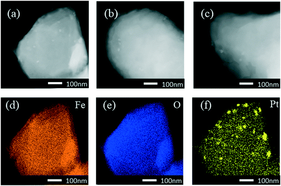
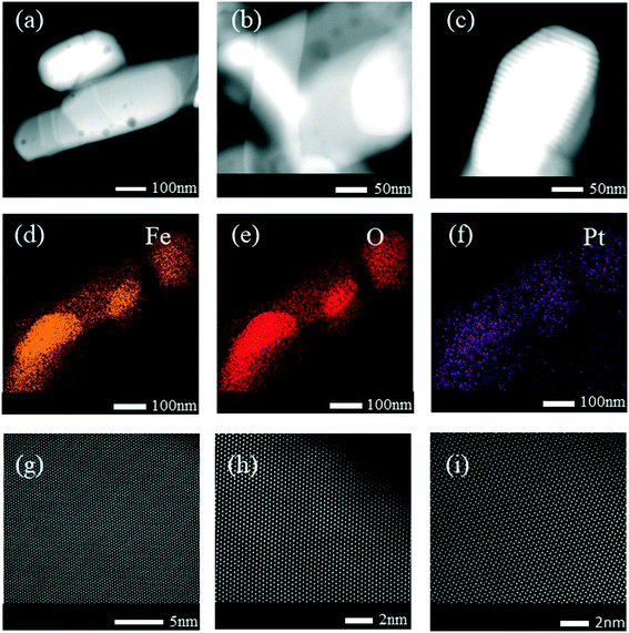
High-angle annular dark-field scanning transmission electron microscopy (HAADF-STEM) revealed small Pt nanoparticles in the sample of 0.3Pt/α-Fe2O3-C550 as shown in Fig. 1. The sample of 0.3Pt/α-Fe2O3-C550 failed to make Pt SACs owing to the lack of necessary high temperature calcination >600 °C, which was consistent well with the DFT calculation in which the evaporation free energy of PtO2 at 600 °C is virtually thermo-neutral or slightly endothermic (0.07 eV) and the experimental results in which the dispersion of Pt nanoparticles into single atoms only occurred by calcination >600 °C.46 However, no obvious Pt nanoparticles or nanoclusters were found by low-magnification HAADF-STEM in the 0.3Pt1/α-Fe2O3-C700 sample as shown in Fig. 2(a–c), despite the fact that elemental analysis ensures the existence of Pt and ICP-OES definitely corroborates the presence of 0.3 wt% Pt. The disappearance of the nanoparticles or nanoclusters of Pt in the 0.3Pt1/α-Fe2O3-C700 sample definitely hints at dispersion and not the loss of Pt element, consistent with the result that only an infinitesimal mass loss of the mixture was observed after applying high-temperature calcination. Aberration-corrected (AC) HAADF-STEM was also performed, and the results are shown in Fig. 2(g–i). However, it failed to detect the single Pt atoms possibly due to the low Pt loading and/or uneven dispersion. But we also found no nanoclusters or particles in the 0.3Pt1/α-Fe2O3-C700 sample by AC HAADF-STEM, conforming with the formation of Pt SACs in a way of elimination. It is noteworthy that the single Pt atoms were mainly located on the surface/subsurface rather than infiltrating into the crystal lattice of α-Fe2O3 to form an interstitial solid solution because Pt and Fe have a similar atomic radius.
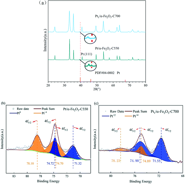
The X-ray diffraction (XRD) results as shown in Fig. 3(a) were consistent with the preceding HAADF-STEM observations. The sample of 0.3Pt/α-Fe2O3-C550 exhibits the reflection characteristics of the rutile structure of α-Fe2O3 carriers and Pt nanoparticles. However, the characteristic reflection of the Pt nanoparticles completely disappeared in the 0.3Pt1/α-Fe2O3-C700 sample, accompanied with the obviously sharpened characteristic reflection of the rutile structure of Fe2O3 carriers, implying severe carrier sintering, in consistence with the huge decrease in the BET specific surface area after indispensable 700 °C calcination. Fig. 3(b and c) show the Pt 4f XPS spectra of 0.3Pt/α-Fe2O3-C550 and 0.3Pt1/α-Fe2O3-C700. In the 0.3Pt/α-Fe2O3-C550 sample, the Pt peaks were deconvoluted into peaks representing Pt0 and Pt4+; Pt4+ possibly comes from the surface oxidation of Pt NPs during calcination, while there are no peaks representing Pt2+. The Pt0 fraction of 0.3Pt/α-Fe2O3-C550 was 40% and the Pt4+ fraction was 60%, estimated from the area ratios. In the 0.3Pt1/α-Fe2O3-C700 sample, the Pt 4f peaks were deconvoluted into peaks representing Pt2+ and Pt4+, while there were no peaks representing Pt0. The Pt2+ fraction of 0.3Pt1/α-Fe2O3-C700 was 81% and the Pt4+ fraction was 19%, estimated from the area ratios, indicating that those Pt single-atoms were quite oxidized.47
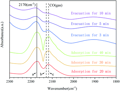
The adsorption of carbon monoxide followed by infrared spectroscopy has often been used to characterize supported transition metals.48 A further investigation on the CO adsorption of 0.3Pt1/α-Fe2O3-C700 using Fourier-transform infrared spectroscopy (FTIR) was carried out to provide additional information about the dispersion and oxidation state of Pt, and the results are shown in Fig. 4. For the adsorption of CO on the sample of 0.3Pt1/α-Fe2O3-C700, only a single band appeared at 2170 cm−1, which can be ascribed to CO adsorbed on the highly oxidized Pt single atoms. Obviously, the band position of CO adsorbed on the highly oxidized Pt was almost unchanged during the adsorption and evacuation processes, consistent with a lack of interaction between the adsorbed CO molecules on Pt because of the isolation of single Pt atoms in 0.3Pt1/α-Fe2O3-C700. Note that the CO vibration wavenumbers (2170 cm−1) of the prepared SACs of 0.3Pt1/α-Fe2O3-C700 are much higher than those of Pt SACs reported,3 consistent with the much higher oxidation state of Pt in this catalyst.
Metal dispersion is vital in catalyst lifetime and activity. Accurate determination of metal dispersion is highly desired for the quantitative evaluation and estimation of degradation.49 Considering the support effect, the application of conventional CO chemisorption may not provide a reliable indication of Pt metal dispersion. However, HAADF-STEM combined with XRD and XPS has been considered a powerful tool to determine the metal dispersion. By applying a combination of these technologies above, we can definitely come to an objective conclusion that the Pt in 0.3Pt1/α-Fe2O3-C700 could be dispersed as atoms, showing almost 100% dispersion.
In a word, though we didn't manage to detect the single Pt atoms in the sample of 0.3Pt1/α-Fe2O3-C700 through the most intuitionistic imaging by AC HAADF-STEM, along with other persuasive characterization data discussed above, we drew a conclusion that this catalyst sample was composed of only isolated, positively charged single Pt atoms. The Pt SACs can be obtained from commercial PtO2 powders by calcining a physical mixture of sub-micron PtO2 aggregates with α-Fe2O3 powders at high temperature.
3.2. Synthesis and characterization of the Pt1/TiO2–α-Fe2O3 SACs
It is no doubt that iron oxides have outstanding efficiency for dispersing commercial PtO2 aggregates into single Pt atoms state at high temperatures, which has a lot to do with their reducibility. But suffering from necessary high-temperature calcination, the mesoporous α-Fe2O3 carriers undergo severe sintering (the BET specific surface area decreases from 88.07 m2 g−1 down to 6.3 m2 g−1 after calcination at 700 °C for 5 hours), having negative effects on the maximum loading and catalytic performance. Here, we fabricated a highly stable and mesoporous anatase by using a simple surfactant sulfuric acid carbonization method. The ordered mesoporous TiO2 materials obtained have excellent thermal stability and a high surface area which is near to 100 m2 g−1 after the calcination at 700 °C for 5 hours. Therefore, the synthesis of Pt SACs from an Fe-substituted TiO2 (TiO2–α-Fe2O3) was investigated to verify the generality of this strategy.The single-atom catalyst of Pt1/TiO2–α-Fe2O3 with a theoretical Pt loading of 4 wt% was fabricated by high temperature calcination (at 700 °C for 5 h) of the physical mixture of commercial PtO2 and a TiO2–α-Fe2O3 complex (denoted as 4Pt1/TiO2–α-Fe2O3-C700). To exclude the possibility of mesoporous TiO2 materials in dispersing commercial PtO2 aggregates into single atom state at high temperatures, other similar catalysts with the Pt loading of 4 wt% and 2 wt% (at 700 °C for 5 h, denoted as 4Pt/TiO2-C700 and 2Pt/TiO2-C700) were also prepared and characterized.
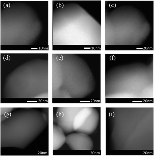
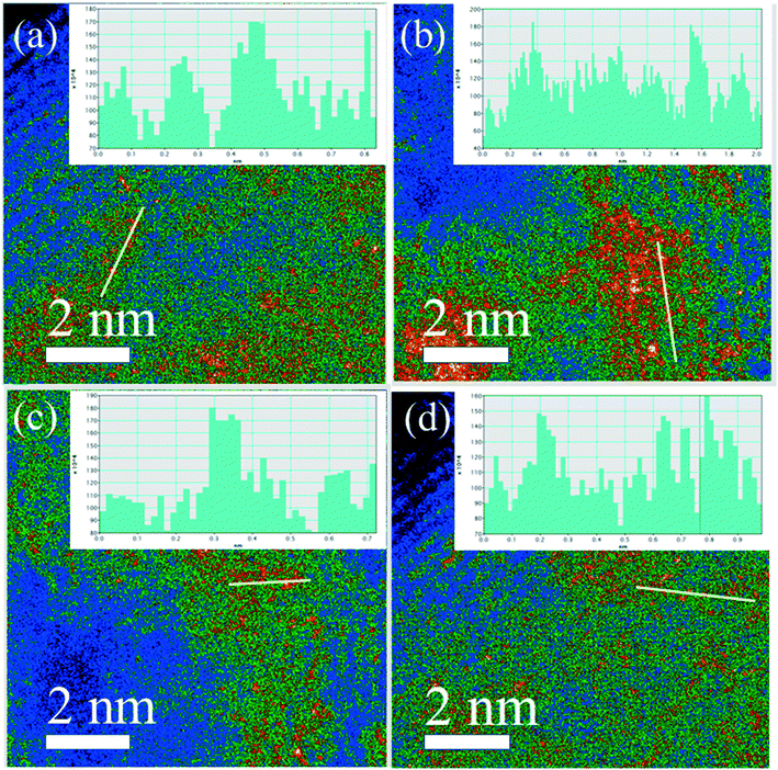
Obviously, the resulting samples of 4Pt/TiO2-C700 and 2Pt/TiO2-C700 contained visible small Pt nanoparticles as shown in Fig. 5(a–f), confirming that mesoporous TiO2 materials were not able to disperse PtO2 clusters into single Pt atom state after calcination at 700 °C. However, no obvious nanoparticles or nanoclusters of Pt were found by low-magnification HAADF-STEM in the sample of 4Pt1/TiO2–α-Fe2O3-C700 as seen in Fig. 5(g–i). ICP-OES definitely corroborates the presence of 4 wt% Pt in the 4Pt1/TiO2–α-Fe2O3-C700 sample. Aberration-corrected (AC) HAADF-STEM was also performed and the intuitionistic imaging of single Pt atoms in the 4Pt1/TiO2–α-Fe2O3-C700 sample was done by AC HAADF-STEM, and the results are shown in Fig. 6(a–d). A conclusion can be drawn that almost all the PtO2 aggregates were dispersed into the single Pt atom state across the TiO2–α-Fe2O3 carrier after the calcination at 700 °C.
3.3. Catalytic performance
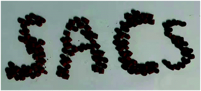
The catalytic oxidation of sulfur dioxide was performed in a microreactor at atmospheric pressure, and the catalytic activities of the as-prepared catalysts as shown in Fig. 7 were measured over a wide temperature range. Blank experiments were performed in the presence of pure α-Fe2O3 or a TiO2–α-Fe2O3 complex. The conversion of SO2 to SO3 as a function of the reaction temperature T is plotted in Fig. 8 and 9 for the different synthesized catalysts.As shown in Fig. 8(a), the catalytic activities of the Pt1/α-Fe2O3 SACs with different Pt loadings and the Pt nanocatalyst are compared in the temperature range of 350–700 °C for the catalytic oxidation of sulfur dioxide. The Pt1/α-Fe2O3 SACs were calcined at 700 °C, the 0.3Pt/α-Fe2O3 nanocatalyst was calcined at 550 °C, and α-Fe2O3 was calcined at 400 °C as the blank reference sample.
Obviously, the blank reference sample α-Fe2O3 had a certain catalytic activity for SO2 oxidation and the ignition temperature was not beyond 550 °C. 0.3Pt/α-Fe2O3-C550 had better catalytic activity than the blank reference sample within the given temperature range, exhibiting a lower light-off temperature, ∼500 °C. The SACs of Pt1/α-Fe2O3 demonstrated greater catalytic activity than the 0.3Pt/α-Fe2O3-C550 sample, suggesting the high atomic efficiency of the SACs. And the catalyst of 0.3Pt1/α-Fe2O3 displayed a higher maximum activity of 46% than 0.2Pt1/α-Fe2O3 (42%), indicating that the catalyst activity can be improved by increasing the Pt loading properly without changing the single atom structure. The SACs of 0.3 Pt1/α-Fe2O3 also exhibited outstanding stability at 600 °C for SO2 oxidation, with a conversion of ∼39% for 1200 min on-stream as seen in Fig. 8(b).
Fig. 9(a) shows the catalytic activity of Pt1/TiO2–α-Fe2O3 with different Pt loadings in the temperature range of 300–700 °C for the catalytic oxidation of sulfur dioxide. The catalyst sample of Pt1/TiO2–α-Fe2O3 was calcined at 700 °C, and TiO2–α-Fe2O3 as the blank reference sample was calcined at 600 °C. Similar to the preceding regularity of the Pt1/α-Fe2O3 SACs, the SACs of Pt1/TiO2–α-Fe2O3 exhibited better catalytic activity than the blank reference sample TiO2–α-Fe2O3 within the given temperature range. And in accordance with the aforesaid observations about the Pt1/α-Fe2O3 SACs, 4Pt1/TiO2–α-Fe2O3-C700 displayed an extremely higher maximum activity (72% at the first cycle) than 2Pt1/TiO2–α-Fe2O3-C700 (32%), which suggested the ultra-high atom efficiency in SACs.
An inquiry into the thermal stability of 4Pt1/TiO2–α-Fe2O3-C700 (in the second cycle) was also performed at 700 °C, as shown in Fig. 9(b), which indicated that the SACs of 4Pt1/TiO2–α-Fe2O3-C700 had good thermal stability.
3.4. Mechanism of PtO2 dispersion
Carriers are very important in SACs because carriers can stabilize isolated atoms by a metal–support interaction or various defects, further affecting catalyst performance. Rui Lang et al. reported that single Pt atoms can be stabilized through a strong covalent metal–support interaction (CMSI) that is not related to carrier defects but associated with carrier (iron oxide) reducibility. A strong CMSI between Fe and Pt is critical to the dispersion process. Pt SACs with high loading and thermal stability were obtained by trapping either the already deposited Pt atoms or the PtO2 units vaporized from Pt nanoparticles during high-temperature calcination over 600 °C. Moreover, this strategy can be extended to non-reducible carriers by simply doping with iron oxide, which also occurs for Fe-doped (but not undoped) Al2O3.46Inspired by this observation, Kaipeng Liu et al. reported the synthesis of Ru SACs from commercial RuO2 powders by calcining a physical mixture of sub-micron RuO2 aggregates with a MgAl1.2Fe0.8O4 spinel or commercial Fe2O3 powders at 900 °C. Detailed studies concluded that the dispersion process is ultimately attributed to anti-Ostwald ripening promoted by a strong covalent metal–support interaction between Pt and Fe and not arising from a gas atom trapping mechanism.36 This synthetic strategy paves a new way for the mass production of high loading SACs with excellent thermal stability for industrial applications.
Taking the above-mentioned aspects into consideration, we got the idea of producing Pt SACs from commercial PtO2 powders by calcining a physical mixture of sub-micron PtO2 aggregates with mesoporous α-Fe2O3 or a TiO2–α-Fe2O3 complex at 700 °C to verify the generality of this strategy. With a combination of convincing characterization data discussed above, we came to the conclusion that Pt SACs can be obtained from commercial PtO2 powders by calcining a physical mixture of sub-micron PtO2 aggregates with α-Fe2O3 or TiO2–α-Fe2O3 at high temperature. PtO2 powders undergo complete dispersion into isolated Pt single atoms after calcination, arising from the anti-Ostwald ripening process promoted by a strong covalent metal–support interaction.
4. Conclusions
Pt SACs with excellent thermal stability were fabricated by calcining a physical mixture of PtO2 and mesoporous α-Fe2O3 or a TiO2–α-Fe2O3 complex at 700 °C and were confirmed by HAADF-STEM, CO-DRIFTS, XRD and other convincing characterization results. The complete dispersion of PtO2 powders into isolated Pt single atoms after calcination was ultimately attributed to anti-Ostwald ripening promoted by a strong covalent metal–support interaction between Pt and Fe. The solid pellet Pt SACs obtained after a typical forming process were tested for the catalytic oxidation of sulfur dioxide. Compared with a blank reference sample, the Pt SACs exhibited better catalytic activity. 4Pt1/TiO2–α-Fe2O3-C700 (first cycle) demonstrated the highest catalytic activity with a ∼72% maximum activity, owing to its high loading and specific surface area. The Pt SACs also possessed good thermal stability and performed well within 1200 min on stream. In one word, this work opens a new route for the large-scale fabrication of thermally stable Pt SACs and paves a new way for the use of Pt SACs for the catalytic oxidation of sulfur dioxide.Conflicts of interest
There are no conflicts to declare.References
- N. Zhang, C. Ye, H. Yan, L. Li, H. He, D. Wang and Y. Li, Nano Res., 2020, 13, 3165–3182 CrossRef CAS.
- G. Xu, F. Liu, Z. Lu, S. H. Talib, D. Ma and Z. Yang, Phys. E, 2021, 130, 114676 CrossRef CAS.
- B. Qiao, A. Wang, X. Yang, L. F. Allard, Z. Jiang, Y. Cui, J. Liu, J. Li and T. Zhang, Nat. Chem., 2011, 3, 634–641 CrossRef CAS PubMed.
- J. Wan, W. Chen, C. Jia, L. Zheng, J. Dong, X. Zheng, Y. Wang, W. Yan, C. Chen, Q. Peng, D. Wang and Y. Li, Adv. Mater., 2018, 30, 1705369 CrossRef PubMed.
- A. Beniya and S. Higashi, Nat. Catal., 2019, 2, 590–602 CrossRef.
- C. Ye, M. Peng, Y. Wang, N. Zhang, D. Wang, M. Jiao and J. T. Miller, ACS Appl. Mater. Interfaces, 2020, 12, 25903–25909 CrossRef CAS PubMed.
- Y.-J. Chen, H.-Y. Zhuo, Y. Pan, J.-X. Liang, C.-G. Liu and J. Li, Sci. China Mater., 2021, 64, 1939–1951 CrossRef CAS.
- X. Liu, M. Xu, L. Wan, H. Zhu, K. Yao, R. Linguerri, G. Chambaud, Y. Han and C. Meng, ACS Catal., 2020, 10, 3084–3093 CrossRef CAS.
- J. Wang, Y. Lu, L. Liu, L. Yu, C. Yang, M. Delferro, A. S. Hoffman, S. R. Bare, A. M. Karim and H. Xin, J. Phys. Chem. C, 2021, 125, 11380–11390 CrossRef CAS.
- S. Yuan, H. Ren, G. Meng, W. Zhao, H. Zhu and W. Guo, Appl. Surf. Sci., 2021, 555, 149682 CrossRef CAS.
- L. Wang, S. Zhang, Y. Zhu, A. Patlolla, J. Shan, H. Yoshida, S. Takeda, A. Frenkel and F. Tao, ACS Catal., 2013, 3, 1011–1019 CrossRef CAS.
- X. Li, Q. Zhou, S. Wang, Y. Li, Y. Liu, Q. Gao and Q. Wu, J. Phys. Chem. C, 2021, 125, 11963–11974 CrossRef CAS.
- X. Lin, L. Li, X. Chang, C. Pei, Z.-J. Zhao and J. Gong, Sci. China Mater., 2021, 64, 1173–1181 CrossRef CAS.
- J. Zhao and Z. Chen, J. Am. Chem. Soc., 2017, 139, 12480–12487 CrossRef CAS PubMed.
- S.-Y. Lv, C.-X. Huang, G. Li and L.-M. Yang, ACS Appl. Mater. Interfaces, 2021, 13, 29641–29653 CrossRef CAS.
- X. Chen, W.-J. Ong, X. Zhao, P. Zhang and N. Li, J. Energy Chem., 2021, 58, 577–585 CrossRef.
- Y. Chen, J. Gao, Z. Huang, M. Zhou, J. Chen, C. Li, Z. Ma, J. Chen and X. Tang, Environ. Sci. Technol., 2017, 51, 7084–7090 CrossRef CAS.
- Z. Huang, X. Gu, Q. Cao, P. Hu, J. Hao, J. Li and X. Tang, Angew. Chem., Int. Ed., 2012, 51, 4198–4203 CrossRef CAS.
- A. Satayavibul and C. Ratanatamskul, J. Environ. Manage., 2021, 279, 111624 CrossRef CAS PubMed.
- S. Ding, H.-A. Chen, O. Mekasuwandumrong, M. J. Hulsey, X. Fu, Q. He, J. Panpranot, C.-M. Yang and N. Yan, Appl. Catal., B, 2021, 281, 119471 CrossRef CAS.
- Y. Guo, R. Lang and B. Qiao, Catalysts, 2019, 9, 135 CrossRef.
- G. Righi, R. Magri and A. Selloni, J. Phys. Chem. C, 2020, 124, 17578–17585 CrossRef CAS.
- W.-Z. Li, M.-Y. Liu, L. Gong, M.-L. Zhang, C. Cao and Y. He, Appl. Surf. Sci., 2021, 560, 150041 CrossRef CAS.
- L. Shang, J.-Q. Wang, C.-Q. Cheng, Y. Zhang, F.-F. Zhang, Y.-M. Xie, J.-D. Lu, J. Mao, Q.-J. Guo, C.-K. Dong, H. Liu and X.-W. Du, J. Alloys Compd., 2021, 874, 159909 CrossRef CAS.
- J. Li, Y. Zhou, W. Tang, J. Zheng, X. Gao, N. Wang, X. Chen, M. Wei, X. Xiao and W. Chu, Appl. Catal., B, 2021, 285, 119861 CrossRef CAS.
- D. Wang, H. Li, N. Du and W. Hou, Adv. Funct. Mater., 2021, 31, 2009770 CrossRef CAS.
- Y. Shi, Z.-R. Ma, Y.-Y. Xiao, Y.-C. Yin, W.-M. Huang, Z.-C. Huang, Y.-Z. Zheng, F.-Y. Mu, R. Huang, G.-Y. Shi, Y.-Y. Sun, X.-H. Xia and W. Chen, Nat. Commun., 2021, 12, 2008151 Search PubMed.
- X. Wang, H. Niu, Y. Liu, C. Shao, J. Robertson, Z. Zhang and Y. Guo, Catal. Sci. Technol., 2020, 10, 8465–8472 RSC.
- J. Sun, H. Zhao, X. Fang, S. Zhai, D. Zhai, L. Sun and W. Deng, Mol. Catal., 2021, 508, 111581 CrossRef CAS.
- S. Wang, P. Zhou, L. Zhou, F. Lv, Y. Sun, Q. Zhang, L. Gu, H. Yang and S. Guo, Nano Lett., 2021, 21, 4262–4269 CrossRef CAS PubMed.
- X. Wan, Z. Zhang, H. Niu, Y. Yin, C. Kuai, J. Wang, C. Shao and Y. Guo, J. Phys. Chem. Lett., 2021, 12, 6111–6118 CrossRef CAS PubMed.
- H. Zhang, S. Sui, X. Zheng, R. Cao and P. Zhang, Appl. Catal., B, 2019, 257, 117878 CrossRef CAS.
- K. Yang, Y. Liu, J. Deng, X. Zhao, J. Yang, Z. Han, Z. Hou and H. Dai, Appl. Catal., B, 2019, 244, 650–659 CrossRef CAS.
- Z. Zhang, Y. Zhu, H. Asakura, B. Zhang, J. Zhang, M. Zhou, Y. Han, T. Tanaka, A. Wang, T. Zhang and N. Yan, Nat. Commun., 2017, 8, 16100 CrossRef CAS PubMed.
- B. Qiao, J.-X. Liang, A. Wang, C.-Q. Xu, J. Li, T. Zhang and J. Liu, Nano Res., 2015, 8, 2913–2924 CrossRef CAS.
- H. Xiong, A. K. Datye and Y. Wang, Adv. Mater., 2021, 2004319 CrossRef.
- L. Cao, W. Liu, Q. Luo, R. Yin, B. Wang, J. Weissenrieder, M. Soldemo, H. Yan, Y. Lin, Z. Sun, C. Ma, W. Zhang, S. Chen, H. Wang, Q. Guan, T. Yao, S. Wei, J. Yang and J. Lu, Nature, 2019, 565, 631–635 CrossRef CAS.
- J. Fonseca and J. Lu, ACS Catal., 2021, 11, 7018–7059 CrossRef CAS.
- H.-W. Liang, S. Brüller, R. Dong, J. Zhang, X. Feng and K. Müllen, Nat. Commun., 2015, 6, 7992–8000 CrossRef CAS.
- Q.-L. Zhu, W. Xia, L.-R. Zheng, R. Zou, Z. Liu and Q. Xu, ACS Energy Lett., 2017, 2, 504–511 CrossRef CAS.
- J.-C. Li, S. Maurya, Y. S. Kim, T. Li, L. Wang, Q. Shi, D. Liu, S. Feng, Y. Lin and M. Shao, ACS Catal., 2020, 10, 2452–2458 CrossRef CAS.
- Y. Pan, R. Lin, Y. Chen, S. Liu, W. Zhu, X. Cao, W. Chen, K. Wu, W.-C. Cheong, Y. Wang, L. Zheng, J. Luo, Y. Lin, Y. Liu, C. Liu, J. Li, Q. Lu, X. Chen, D. Wang, Q. Peng, C. Chen and Y. Li, J. Am. Chem. Soc., 2018, 140, 4218–4221 CrossRef CAS.
- Z. Xiao, Y. Xia, Z. Ren, Z. Liu, G. Xu, C. Chao, X. Li, G. Shen and G. Han, J. Mater. Chem., 2012, 22, 20566–20573 RSC.
- R. Zhang, B. Tu and D. Zhao, Chem. – Eur. J., 2010, 16, 9977–9981 CrossRef CAS PubMed.
- K. Liu, X. Zhao, G. Ren, T. Yang, Y. Ren, A. F. Lee, Y. Su, X. Pan, J. Zhang, Z. Chen, J. Yang, X. Liu, T. Zhou, W. Xi, J. Luo, C. Zeng, H. Matsumoto, W. Liu, Q. Jiang, K. Wilson, A. Wang, B. Qiao, W. Li and T. Zhang, Nat. Commun., 2020, 11, 1263 CrossRef CAS.
- R. Lang, W. Xi, J.-C. Liu, Y.-T. Cui, T. Li, A. F. Lee, F. Chen, Y. Chen, L. Li, L. Li, J. Lin, S. Miao, X. Liu, A.-Q. Wang, X. Wang, J. Luo, B. Qiao, J. Li and T. Zhang, Nat. Commun., 2019, 10, 234 CrossRef.
- H. Jeong, D. Shin, B.-S. Kim, J. Bae, S. Shin, C. Choe, J. W. Han and H. Lee, Angew. Chem., Int. Ed., 2020, 59, 20691–20696 CrossRef CAS.
- P. Bazin, O. Saur, J. C. Lavalley, M. Daturi and G. Blanchard, Phys. Chem. Chem. Phys., 2005, 7, 187–194 RSC.
- T. Takeguchi, S. Manabe, R. Kikuchi, K. Eguchi, T. Kanazawa, S. Matsumoto and W. Ueda, Appl. Catal., A, 2005, 293, 91–96 CrossRef CAS.
| This journal is © The Royal Society of Chemistry 2022 |

