Propensity rules for photoelectron circular dichroism in strong field ionization of chiral molecules
Received
1st December 2021
, Accepted 10th February 2022
First published on 17th February 2022
Abstract
Chiral molecules ionized by circularly polarized fields produce a photoelectron current orthogonal to the polarization plane. This current has opposite directions for opposite enantiomers and provides an extremely sensitive probe of molecular handedness. Recently, such photoelectron currents have been measured in the strong-field ionization regime, where they may serve as an ultrafast probe of molecular chirality. Here we provide a mechanism for the emergence of such strong-field photoelectron currents in terms of two propensity rules that link the properties of the initial electronic chiral state to the direction of the photoelectron current.
1 Introduction
Molecular chirality plays a key role in the operation of living organisms, production of drugs, fragrances, agrochemicals, and molecular machines.1 Thus, creating new schemes for efficient chiral discrimination and enantioseparation is important from fundamental and practical standpoints.
The photoionization of an isotropic ensemble of chiral molecules with circularly polarized light belongs to a new set of methods for discriminating molecular enantiomers without the help of the magnetic component of the light field and therefore in a new and extremely efficient way.2 Photoionization causes a pronounced forward–backward asymmetry (FBA) in the photoelectron angular distribution (PAD)3–5 that depends on the relative handedness between the sample and the “electric field + detector” system.2 This phenomenon, known as photoelectron circular dichroism (PECD), has been the subject of an increasing number of investigations in the one- and few-photon regimes,6–9 and very recently it was also observed in the many-photon tunneling regime.10,11
In a previous work12 we introduced three families of chiral wave functions, classified according to the origin of their chirality, and built from hydrogenic wave functions. We used these wave functions to understand how the chirality of the initial state can lead to PECD in the one-photon case in a simplified setting where the continuum states are isotropic and the molecules are aligned perpendicular to the polarization plane. We found that in this case PECD emerges as the result of two simple propensity rules that explicitly connect the circular motion of the electron in the plane of the circularly polarized field with the linear motion perpendicular to the plane, responsible for the FBA. Now we turn our attention to the understanding of PECD in the many-photon ionization regime by taking advantage of the atomic nature of the chiral hydrogenic wave functions, which is ideally suited to include the effect of chirality in the PPT analytical theory of strong field ionization.13 As in our previous work, we will approach this problem in a simplified setting where: (i) the molecules are assumed to be aligned perpendicular to the polarization plane and (ii) the effect of the anisotropy of the molecular potential on the photoelectron is neglected. Assumption (i) is experimentally achievable and assumption (ii) is reasonable in the tunneling picture, where the electron exits the tunnel far from the parent ion.†
There is an important link between assumptions (i) and (ii). Assumption (ii) follows directly from the strong field approximation, which assumes that the interaction between the liberated electron and the parent ion is negligible in comparison to that between the electron and the laser field. This omission results in photoelectron states lacking any dependence on molecular orientation, which in turn results on a perfect cancellation of PECD upon averaging over molecular orientations if the molecules are randomly oriented,8i.e. if all orientations are equally likely. In that case, including molecular corrections to the photoelectron description is necessary in order to get a non-vanishing PECD.8 However, if the molecules are not randomly oriented, the orientation averaging integral has different weights for different orientations and the cancellation of PECD does not occur. That is, in the aligned case [assumption (i)], molecular corrections to the photoelectron state are not essential for the emergence of PECD and we thus neglect them [assumption (ii)] with the intention of keeping our model and our interpretations as simple and clear as we can. Possible ways of extending our model to take into account molecular corrections in the continuum are discussed in Section 5.
2 Physical picture
We will study the photoionization produced by the interaction between a circularly polarized (σ = ±1) electric field of amplitude ![[scr E, script letter E]](https://www.rsc.org/images/entities/char_e140.gif) and frequency ω, propagating along the z axis,
and frequency ω, propagating along the z axis,| |  | (1) |
and a chiral hydrogen atom12 in the initial state| | 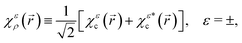 | (2) |
where| | 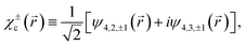 | (3) |
| | 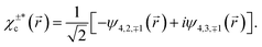 | (4) |
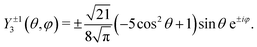
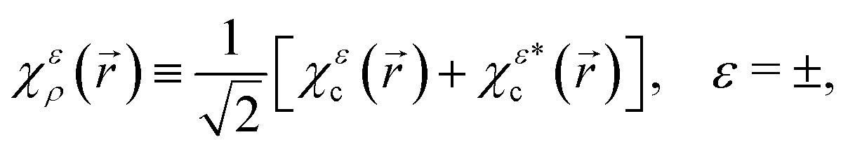
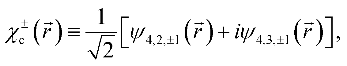
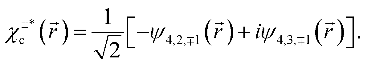
Here the superscript ε = ± indicates the handedness of chiral states, ψn,l,m denotes the hydrogenic state with principal quantum number n, angular momentum quantum number l, and magnetic quantum number m. Eqn (4) follows from eqn (3) and the property of spherical harmonics  . The states χερ and χεc are instances of the chiral-density and chiral-current families of hydrogenic chiral states introduced in ref. 12, respectively. The superscript ε = ± indicating the enantiomer simply corresponds to the sign of m, as can be seen in eqn (2)–(4). Opposite enantiomers (+ and −) are related to each other through a reflection in the y = 0 plane, which by definition is equivalent to a reversal of the sign of m used in the corresponding hydrogenic wave functions.
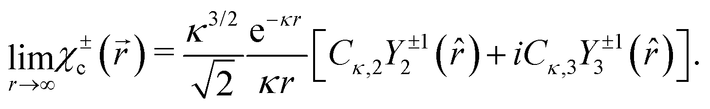
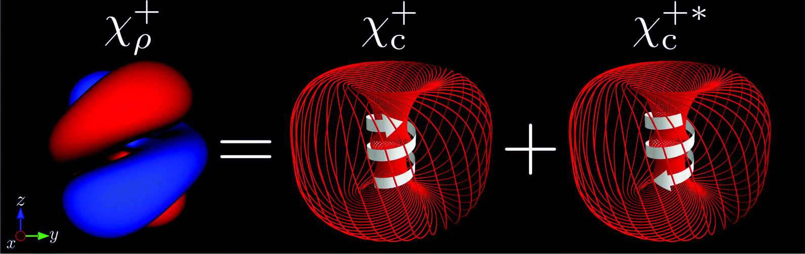
Although both χερ and χεc display chirality, it manifests itself differently in each state. As can be seen in Fig. 1 for ε = +, the chirality of χερ is encoded in its helical probability density |χερ(![[r with combining right harpoon above (vector)]](https://www.rsc.org/images/entities/i_char_0072_20d1.gif) )|2, while the chirality of χεc is encoded in its torus-knot-like probability current
)|2, while the chirality of χεc is encoded in its torus-knot-like probability current ![[j with combining right harpoon above (vector)]](https://www.rsc.org/images/entities/i_char_006a_20d1.gif) (; χεc), which is visualized in Fig. 1via the trajectory followed by an element of the probability fluid |χεc()|2. In analogy to how a standing plane wave can be decomposed into two plane waves traveling in opposite directions, eqn (2) shows how the chiral density state χερ(), which corresponds to a real function and therefore has no probability current, can be decomposed into two chiral current states χεc() and
(; χεc), which is visualized in Fig. 1via the trajectory followed by an element of the probability fluid |χεc()|2. In analogy to how a standing plane wave can be decomposed into two plane waves traveling in opposite directions, eqn (2) shows how the chiral density state χερ(), which corresponds to a real function and therefore has no probability current, can be decomposed into two chiral current states χεc() and  , with opposite probability currents (; χεc) and
 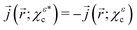 .
.
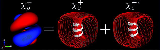 |
| | Fig. 1 Sketch of the decomposition of the chiral density state χ+ρ into the chiral current states χ+c and  , see eqn (2) and ref. 12. Left: Isosurfaces |χ+ρ()| = ±0.001 a.u. Right: Trajectory followed by an element of the probability fluid |χ+c()|2 for the states χ+c and , see eqn (2) and ref. 12. Left: Isosurfaces |χ+ρ()| = ±0.001 a.u. Right: Trajectory followed by an element of the probability fluid |χ+c()|2 for the states χ+c and  . The white arrows indicate the direction of the flow. . The white arrows indicate the direction of the flow. | |
Both in the one- and in the many-photon regimes, the photoionization yield depends on the relative sense of rotation between the circularly polarized electric field and the bound electronic current in the plane of polarization. In the one-photon regime the total photoionization yield is greater when the bound electron and the field rotate in the same direction,14 while in the many-photon regime it is greater when the electron and the field rotate in opposite directions.15–20 We shall call this dependence propensity rule 1 (PR1). Furthermore, we have shown in ref. 12 that in the one-photon case, the component of the bound electronic current perpendicular to the plane of polarization in the region close to the core jz( → 0; χεc) is projected onto the continuum by the ionizing photon, and gives rise to an excess of photoelectrons either in the forward (+z) or backward (−z) direction. We shall call this dependence propensity rule 2 (PR2). Therefore, even though in the state χερ the electron currents of χεc and  cancel each other, PR1 determines which state, χεc or
  , dominates the photoelectron spectrum, and PR2 applied to the dominant state determines whether more electrons go forwards or backwards. As mentioned above, we know that PR1 is reversed when going from the one- to the many-photon regime, and we know the form of PR2 in the one-photon regime. In the many-photon regime, the adiabatic tunneling picture suggests that the photoelectron current along z will reflect that of the bound wave function under the barrier and in the vicinity of the tunnel exit, because of the continuity of the wave function χεc() and its derivatives
  across the exit of the tunnel. Since jz(; χεc) has opposite signs close to and far from the core and the tunnel exit is far from the core, this means that PR2 will also be reversed when going from the one- to the many-photon regime. The simultaneous reversal of PR1 and PR2 when passing from the one- to the many-photon regime means that overall, the FBA resulting from photoionization of χερ will have the same sign in both regimes, that is, if more photoelectrons are ejected forward (backward) for an initial state χερ and a given polarization of the electric field in the one-photon regime, this will also be the case in the many-photon regime. Below we apply the PPT theory of strong-field ionization to chiral hydrogen to prove the physical picture described in this section.
3 Theory
3.1 Strong field ionization of atomic states
Following the PPT theory,13,17,21 one can show that the cycle-averaged current probability density asymptotically far from the nucleus resulting from strong field ionization of an atom in an initial state ψl,mvia a long and circularly polarized pulse [eqn (1)] can be expressed as a sum over multiphoton channels according to| |  | (5) |
where ![[k with combining right harpoon above (vector)]](https://www.rsc.org/images/entities/i_char_006b_20d1.gif) n is the photoelectron momentum measured at the detector, it is parallel to , and its magnitude satisfies
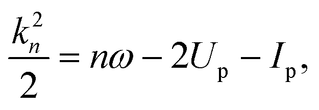
n is the photoelectron momentum measured at the detector, it is parallel to , and its magnitude satisfies| |  | (6) |
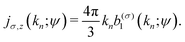
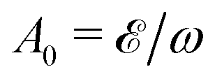
n is the number of absorbed photons, 2Up = A20/2 is the average kinetic energy of an electron in the circularly polarized electric field (1),  is the amplitude of the vector potential, Ip is the ionization potential, and n0 is the minimum number of photons required for ionization in a strong field. Wσ(n; ψl,m) is the probability of populating a Volkov state with drift momentum n,17i.e. it is the PAD at energy k2n/2,
| |  | (7) |
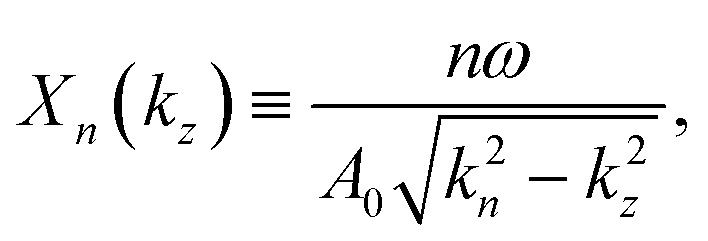
where we defined‡| | 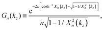 | (8) |
| |  | (9) |
 is the wave function of the initial state in the momentum representation,
| |  | (10) |
and ![[v with combining right harpoon above (vector)]](https://www.rsc.org/images/entities/i_char_0076_20d1.gif) nσ(ti) ≡ n +
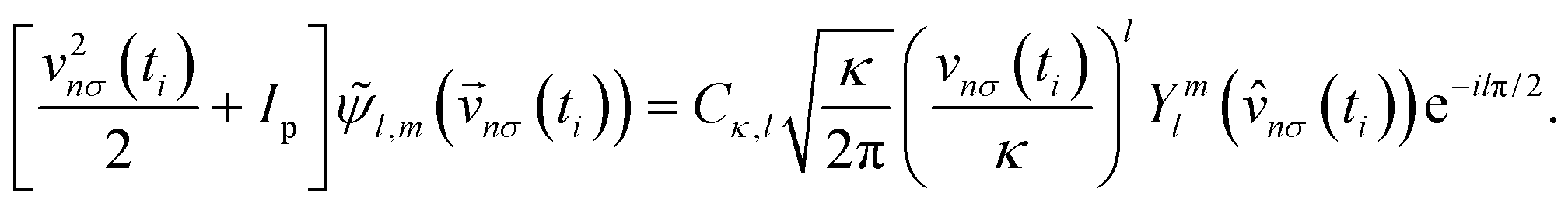
nσ(ti) ≡ n + ![[A with combining right harpoon above (vector)]](https://www.rsc.org/images/entities/i_char_0041_20d1.gif) σ(ti) is the velocity of the electron, which depends on the vector potential σ(ti) at the complex time ti.§ The latter is defined through the saddle point equation v2nσ(ti) = −2Ip, and corresponds to the time at which the electron enters the potential barrier that results from the bending of the binding potential by the strong electric field.21 Despite the saddle point equation vnσ2(ti) = −2Ip, eqn (7) does not vanish because n(ti) is a pole of
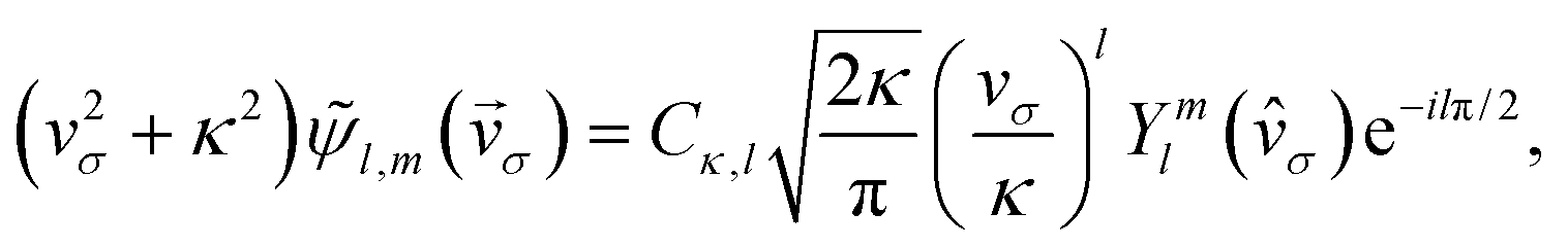
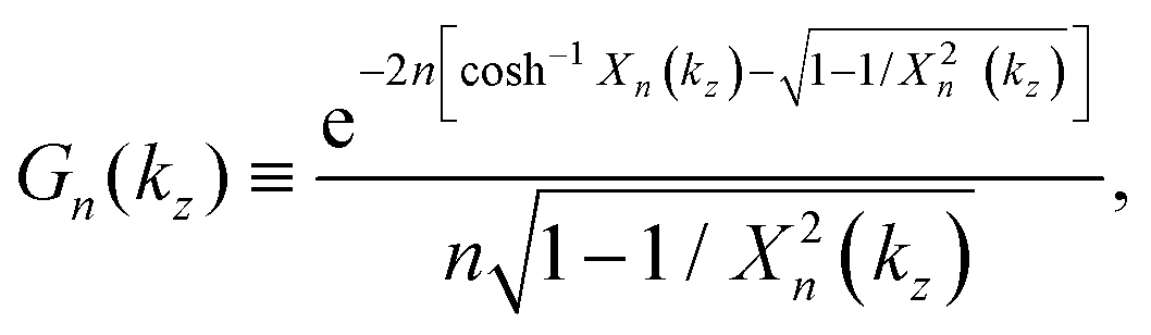
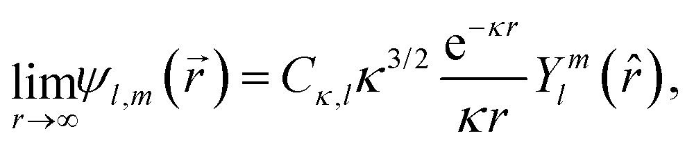
σ(ti) is the velocity of the electron, which depends on the vector potential σ(ti) at the complex time ti.§ The latter is defined through the saddle point equation v2nσ(ti) = −2Ip, and corresponds to the time at which the electron enters the potential barrier that results from the bending of the binding potential by the strong electric field.21 Despite the saddle point equation vnσ2(ti) = −2Ip, eqn (7) does not vanish because n(ti) is a pole of ![[small psi, Greek, tilde]](https://www.rsc.org/images/entities/i_char_e0e3.gif) l,m(). Furthermore, since the behavior of the wave function in momentum space l,m() close to a pole vσ(ti) only contains information about the asymptotic part of its counterpart in coordinate space ψl,m(),13,22 the latter can be replaced by its asymptotic form, which for a spherically-symmetric short-range potential is given by
l,m(). Furthermore, since the behavior of the wave function in momentum space l,m() close to a pole vσ(ti) only contains information about the asymptotic part of its counterpart in coordinate space ψl,m(),13,22 the latter can be replaced by its asymptotic form, which for a spherically-symmetric short-range potential is given by| |  | (11) |
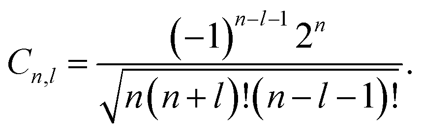
and where the constant Cκ,l contains the information about the short-range behavior of ψl,m(). Using eqn (11) one can show17 that the fingerprint of the initial state on the PAD [eqn (7)] reduces to| | 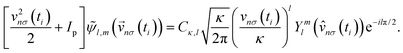 | (12) |
3.2 Strong field ionization of a chiral state
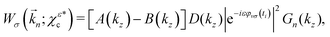
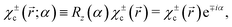
Up to this point the theory has followed ref. 17, which assumes an initial state ψl,m with well defined angular momentum quantum numbers (l, m), and therefore a central potential. To obtain enantio-sensitive currents triggered by strong field ionization, we will replace the initial state ψl,m() in the derivation above by a chiral hydrogen state, where| |  | (13) |
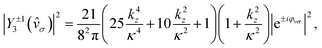
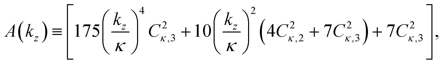
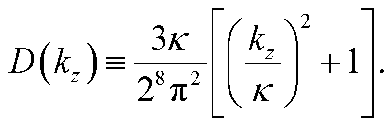
Replacing ψl,m() by χεc(), and using the corresponding asymptotic expression (11) for each partial wave in χεc() yields (see Appendix)| | | Wσ(n; χεc) = [A(kz) + B(kz)]D(kz)|eiεφvσ(ti)|2Gn(kz), | (14) |
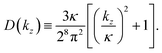
where A(kz) and D(kz) are even polynomials of kz while B(kz) is an odd polynomial of kz,| | 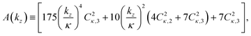 | (15) |
| | 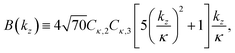 | (16) |
| |  | (17) |
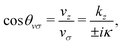
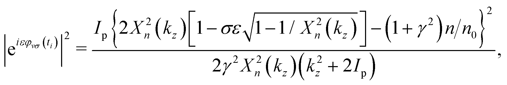
The factor |eiεφvσ(ti)|2, which is not equal to unity because the so-called tunneling-momentum angle φvσ(ti) is complex, gives rise to PR1, and is given by15,17| | 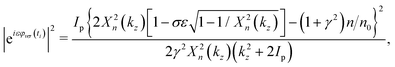 | (18) |
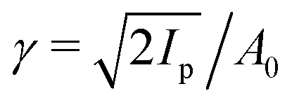
where  is the Keldysh parameter.23 As expected from symmetry, this term behaves so that a reversal of the polarization σ is equivalent to a reversal of the azimuthal probability current of the bound state in the polarization plane sgn
![[thin space (1/6-em)]](https://www.rsc.org/images/entities/char_2009.gif) m = ε, i.e.
m = ε, i.e.| | | |eiεφv,−σ(ti)|2 = |e−iεφv,σ(ti)|2. | (19) |
In other words, the angle-integrated yield is only affected by the relative direction of the probability current of the bound state in the polarization plane with respect to the direction of rotation of the electric field. Furthermore, since in the case we are considering, opposite values of m correspond to opposite enantiomers, we have that for the χεc states, opposite enantiomers subject to opposite polarizations display the same angle-integrated yield.
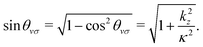
Since A(kz), D(kz), |eiεφv,σ(ti)|2, and Gn(kz) are even functions of kz, eqn (14) shows that the FBA is entirely encoded in the odd polynomial B(kz). Furthermore, since sgn (Cκ,l+1Cκ,l) = −1,¶ we can see from the expression for B(kz) and from eqn (14) that more photoelectrons will be emitted backwards (−z) than forwards (+z), for either polarization σ = ±1 of the electric field.
From the expressions for χεc and  [eqn (3) and (4)] and from eqn (14)–(16), it follows that the PAD for the complex conjugated state
  reads
reads
| |  | (20) |
which differs from the corresponding equation for
χεc [
eqn (14)] in the signs in front of
B(
kz) and
ε. This shows that

yields a FBA exactly opposite to that of
χεc.
Eqn (14) and (20) yield the following important conclusions:
First, they confirm our expectation that the FBA is determined by the direction of the bound probability current close to the tunnel exit.
Second, the product of Cκ,2 and Cκ,3 in eqn (16) shows that the FBA emerges exclusively from the interference between the two components, ψ4,2,±1 and iψ4,3,±1, that make up the χεc state. As can be seen in the Appendix, this interference vanishes when the relative phase between the two components is ±π. That is, the chiral states  introduced in ref. 12, which instead of a probability current along z have probability density polarized along z (see Fig. 1 in ref. 12), do not display any FBA in the case of strong field of ionization.
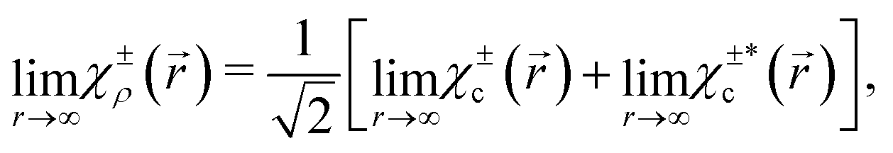
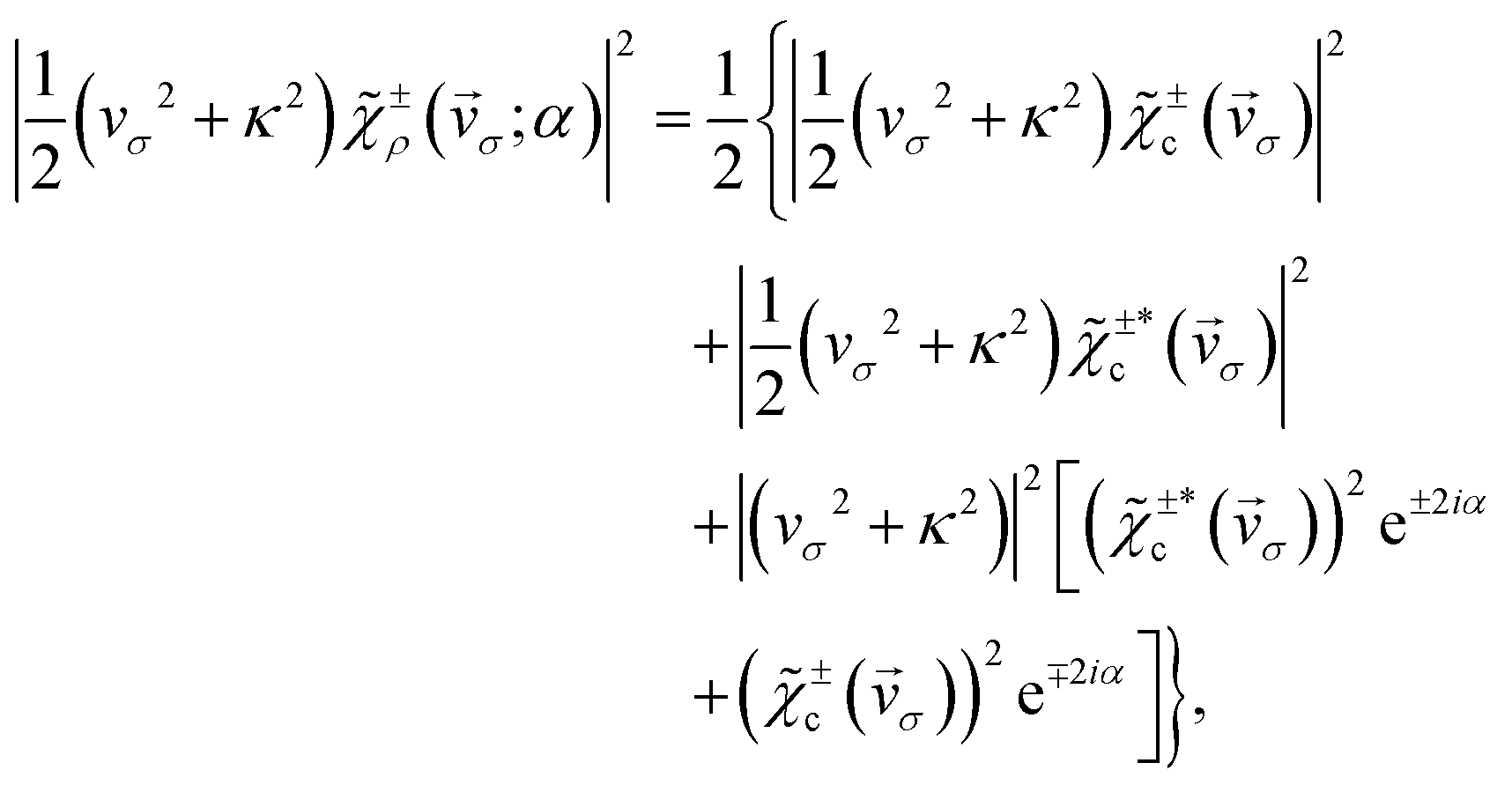
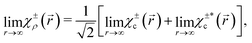
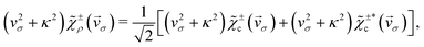
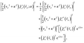
For the state χερ, which has a chiral probability density and can be decomposed into states χεc and  , one can show (see Appendix) that the PAD at energy k2n/2, averaged over the contributions of all initial state orientations related to the original orientation [eqn (2)] by a rotation Rz(α) of α radians around the z axis (as would be appropriate if the state is perfectly aligned along the z axis||), is given by the sum of the PADs for the states χεc* and
  [eqn (14) and (20)],
| | 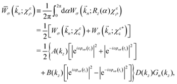 | (21) |
Eqn (21) clearly shows that the asymmetric response along z encoded in B(kz) is coupled to the dichroic and enantio-sensitive response encoded in the difference |eiεφvσ(ti)|2 − |e−iεφvσ(ti)|2, so that either opposite enantiomers (opposite values of ε) or opposite circular polarizations (opposite values of σ) yield opposite FBAs [see eqn (19)]. That is, the enantiosensitive and dichroic response is encoded entirely in the second term of eqn (21). Furthermore, unlike χεc and  , which have different angle-integrated yields for either opposite enantiomers or opposite circular polarizations, the angle-integrated photoelectron yield for the initial state χερ is independent of the enantiomer and circular polarization used. This is because the contribution from the second term in eqn (21) to the angle integrated yield vanishes and the first term in eqn (21) is explicitly symmetric with respect to a reversal of either polarization or enantiomer.
Using eqn (19) we get that the ratio of the dichroic and non-dichroic responses, which is equivalent to the ratio of enantiosensitive and non-enantiosensitive responses, is given by
| | 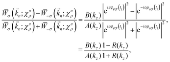 | (22) |
where
R ≡ |e
−iεφvσ(ti)|
2/|e
iεφvσ(ti)|
2 is the ratio of ionization rates of co- and counter-rotating electrons [see eqn (100) in ref.
24].
4 Calculations
In view of the results obtained in ref. 2, 12 and 25, we will base our analysis on the photoelectron current**(n; ψ) associated with the photoelectron of momentum n and the initial state ψ,For a given n-photon channel, the net photoelectron current along z reads| | 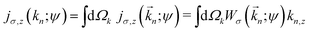 | (24) |
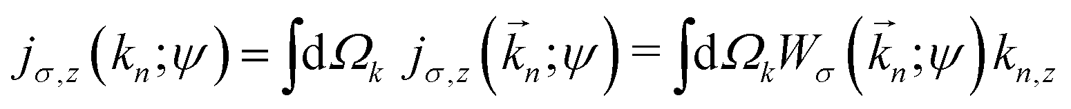
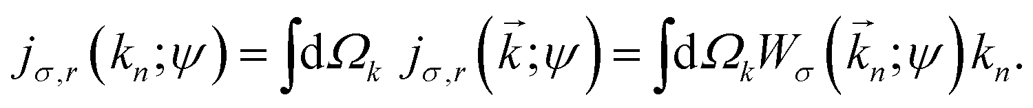
where the integration is over directions of n. Due to the symmetry of the system, jσ,z(n) is the only non-zero Cartesian component of σ(n). The angle-integrated radial component of the photoelectron current is also of interest as it determines the total ionization yield. It is given by| | 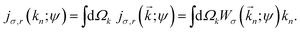 | (25) |
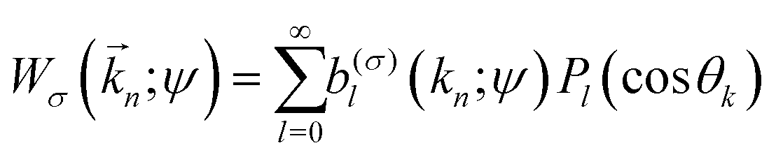
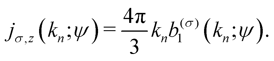
As shown in ref. 2 and 12 and as can be seen from eqn (24) and (25), if one expands the PAD in Legendre polynomials,| | 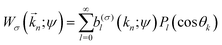 | (26) |
it becomes clear that the radial and z components of the current are proportional to the zeroth and first order coefficients, respectively,| | | jσ,r(kn; ψ) = 4πknb(σ)0(kn;ψ), | (27) |
| |  | (28) |
Clearly, only the kz-even part of Wσ contributes to jσ,r and only the kz-odd part of Wσ contributes to jσ,z. For the states χεc,  , and χερ this means that only the part of Wσ involving A(kz) contributes to jσ,r and only the part of Wσ involving B(kz) contributes to jσ,z.
Fig. 2 shows the photoelectron current along the z axis as a function of the photoelectron momentum at the detector for all the different enantiomer–polarization configurations involving the χεc and χερ states, and left- and right circular polarizations in the xy plane, and for an electric field amplitude = 0.06 a.u. (I = 1.3 × 10¹⁴ W cm−2), angular frequency ω = 0.057 a.u. (λ = 800 nm), and ionization potential Ip = 0.5 a.u., which yield a Keldysh parameter 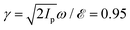 corresponding to non-adiabiatic tunneling ionization. The results in Fig. 2 clearly show how the FBA is governed by the propensity rules discussed in Section 2. Panel (b) shows how for the states χεc, the direction of the net photoelectron current coincides with that of the bound probability current in the region close to the tunnel exit (vertical arrow), that is, where x2 + y2 ≫ 1 and |z| ≪ 1. We can also see to what extent the intensity of the photoelectron current is greater when the bound probability current (green circular arrow) and the electric field (red or blue circular arrows) circulate in opposite directions. Panel (c) of Fig. 2 shows the corresponding results for the initial state χερ. Although χερ does not display any bound probability currents, it yields a non-zero net photoelectron current along the z direction, consistent with its decomposition into χεc and
  . This decomposition along with the propensity rules for the χεc states dictate that the photoelectron current will flow in the direction corresponding to the χεc component that has a bound probability current counter-rotating with the electric field.
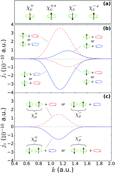 |
| | Fig. 2 Photoelectron current density along z as a function of photoelectron momentum [eqn (24)], resulting from strong field ionization of the initial states χεc,  , and χερ [eqn (2)–(4) and Fig. 1], via intense light circularly polarized in the xy plane. (a) Diagrams indicating the directions of the azimuthal component (green circular arrow) and the vertical component of the probability current in the region close to the tunnel exit (black vertical arrow) in the bound states χεc and , and χερ [eqn (2)–(4) and Fig. 1], via intense light circularly polarized in the xy plane. (a) Diagrams indicating the directions of the azimuthal component (green circular arrow) and the vertical component of the probability current in the region close to the tunnel exit (black vertical arrow) in the bound states χεc and  . (b) Photoelectron current [eqn (7), (14), (20) and (24)] for different combinations of initial state [indicated according to (a)] and light polarization (red or blue circular arrow after the plus sign). Note that the direction of jz is determined by the direction of the vertical component of the bound current in the region close to the tunnel exit (black vertical arrow). Except for the high-momentum tail beyond k ≈ 1.5 a.u., the magnitude of jz is greater when the azimuthal bound probability current (green arrow) and the ionizing light (red or blue arrow) rotate in opposite directions. (c) Same as (b) but for the initial state χερ after averaging over the orientations of the initial state that result from a rotation around the z axis [eqn (7), (21) and (24)]. The state χερ is indicated with the two consecutive diagrams corresponding to its decomposition into states χεc and . (b) Photoelectron current [eqn (7), (14), (20) and (24)] for different combinations of initial state [indicated according to (a)] and light polarization (red or blue circular arrow after the plus sign). Note that the direction of jz is determined by the direction of the vertical component of the bound current in the region close to the tunnel exit (black vertical arrow). Except for the high-momentum tail beyond k ≈ 1.5 a.u., the magnitude of jz is greater when the azimuthal bound probability current (green arrow) and the ionizing light (red or blue arrow) rotate in opposite directions. (c) Same as (b) but for the initial state χερ after averaging over the orientations of the initial state that result from a rotation around the z axis [eqn (7), (21) and (24)]. The state χερ is indicated with the two consecutive diagrams corresponding to its decomposition into states χεc and  . In this case, jz is the average of the results obtained for each of its components in (b) [see eqn (21)]. The results shown are for a field of amplitude = 0.06 a.u. and frequency ω = 0.057 a.u., and for an ionization potential Ip = 0.5 a.u. . In this case, jz is the average of the results obtained for each of its components in (b) [see eqn (21)]. The results shown are for a field of amplitude = 0.06 a.u. and frequency ω = 0.057 a.u., and for an ionization potential Ip = 0.5 a.u. | |
The marked dependence of the photoelectron yield on the relative direction between the bound probability current and the circularly polarized electric field (PR1) can be clearly visualized in Fig. 3, which is the analog of Fig. 2 for the radial component of the photoelectron current. Note that for the χερ states the total photoelectron yield jr(k) is independent of both enantiomer and circular polarization.
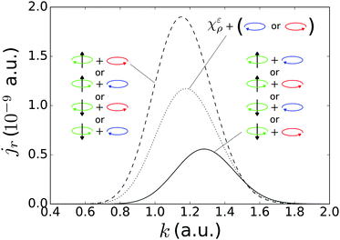 |
| | Fig. 3 Radial component of the photoelectron current density (ionization rate) as a function of photoelectron momentum, resulting from strong field ionization of the initial states χεc and  [see eqn (2)–(4) and Fig. 2(a)], via intense light circularly polarized in the xy plane. Up to k ≈ 1.5 a.u. all the counter-rotating setups, where the azimuthal part of the bound probability current and the light rotate in opposite directions, yield a higher jr. Beyond k ≈ 1.5 a.u. the co-rotating setups yield a higher jr. The corresponding curve for the states χερ is simply the average between the two curves shown and is independent of enantiomer and light polarization. The parameters, , ω, and Ip are the same as in Fig. 2. [see eqn (2)–(4) and Fig. 2(a)], via intense light circularly polarized in the xy plane. Up to k ≈ 1.5 a.u. all the counter-rotating setups, where the azimuthal part of the bound probability current and the light rotate in opposite directions, yield a higher jr. Beyond k ≈ 1.5 a.u. the co-rotating setups yield a higher jr. The corresponding curve for the states χερ is simply the average between the two curves shown and is independent of enantiomer and light polarization. The parameters, , ω, and Ip are the same as in Fig. 2. | |
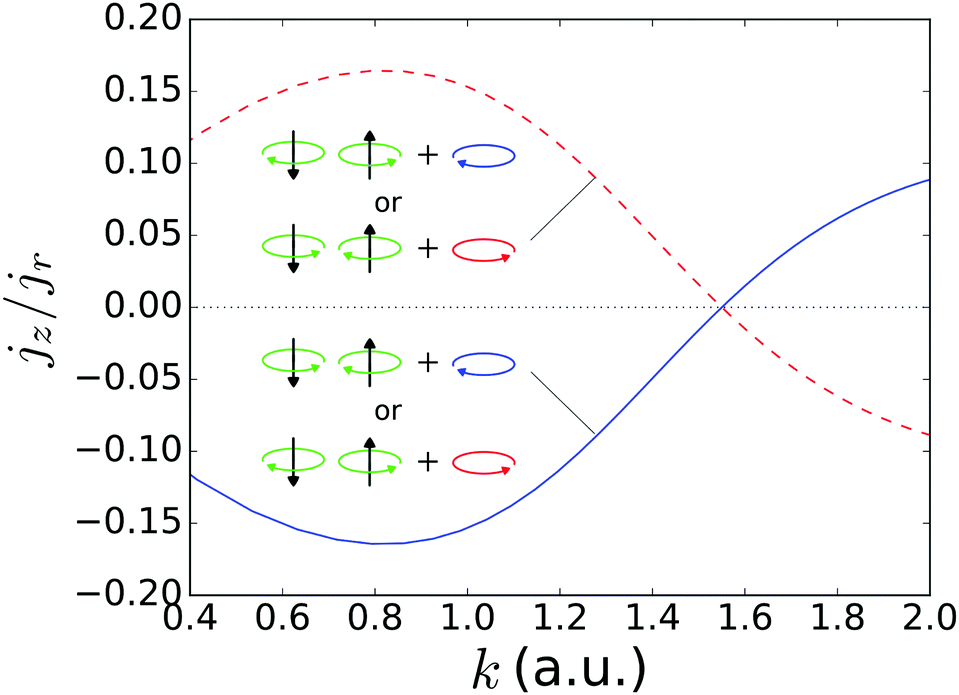
Fig. 4 shows the ratio of the net photoelectron current jz(k) to the total photoelectron current jr(r) released by the strong field. This ratio represents how much of the measured signal displays enantio-sensitivity and dichroism. Its magnitude is similar to what is typically found in the one- and few-photon absorption case, i.e. on the order of 10%, in agreement with recent experimental results.10,11Fig. 4 also displays a clear reversal of the FBA in the high energy tail of the photoelectron spectrum (not so evident in Fig. 2 and 3 because of the small yield at such photoelectron momenta), which is due to the corresponding reversal of PR1 (see Fig. 3 of ref. 17). While such reversal was not decidedly observed in ref. 10 (see Fig. 3f there), it has emerged in more recent experiments (see e.g. Fig. 2e in ref. 11) and state-of-the-art simulations (see Fig. 2 in ref. 26).
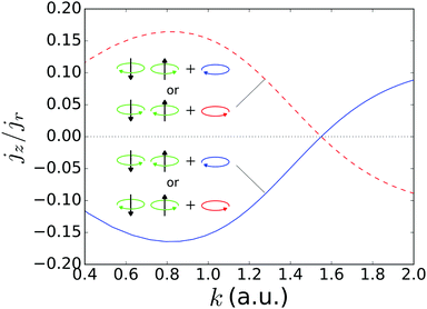 |
| | Fig. 4 Ratio of the z component to the radial component of the photoelectron current density as a function of the photoelectron momentum, resulting from strong field ionization of the initial states χερ [see eqn (2)–(4) and Fig. 2(c) for explanation of symbols], via intense light circularly polarized in the xy plane. Note that the asymmetric part of the signal (i.e. jz), which encodes the dichroic and enantiomeric response, reaches up to about 15% of the total signal jr. Furthermore, it changes sign for high values of the momentum because the propensity rule for strong field ionization of co-rotating and counter-rotating electrons is reversed there (see Fig. 3). | |
5 Conclusions
We have studied the emergence of photoelectron circular dichroism in the strong field regime by introducing a chiral initial state in the PPT formalism of strong field ionization in a simplified setting where we consider aligned molecules and we ignore the effect of the anisotropic molecular potential on the photoelectrons. We derived an equation [eqn (21)] for the photoelectron angular distribution that explicitly displays photoelectron circular dichroism, i.e. it contains a term which describes an asymmetry perpendicular to the polarization plane of the light and changes sign for opposite circular polarizations and for opposite enantiomers. We computed the photoelectron angular distributions for a Keldysh parameter γ = 0.95 and found asymmetries of the order of 10%.
We found that the mechanism and the sign of the forward-backward asymmetry in PECD in the regime of strong field ionization can be understood as the result of the interplay of two propensity rules: (i) the strong field ionization rate depends on the relative rotation directions of the electric field and the bound electron, being higher when the electron and the electric field rotate in opposite directions15,16,18–20,24,27 (ii) The ‘forward–backward’ asymmetry depends on the direction of the current of the initial state in the region of the tunnel exit, the photoelectron is more likely to be emitted ‘forwards’ (‘backwards’) if the probability current of the initial state in the tunnel exit region points ‘forwards’ (‘backwards’). Propensity rule (i) is reversed in the high energy tail of the photoelectron spectrum, which leads to a reversal of the PECD in that region, in agreement with recent experiments11 and simulations.26 For a real initial state, these two propensity rules can be applied by first decomposing the chiral probability density state into two states with opposite azimuthal currents. In comparison to the one-photon regime,12,25 we find that both propensity rules are reversed and thus the same sign of photoelectron circular dichroism is observed in the one- and in the many-photon regime for the states studied.
Excitation of chiral states in atoms28 and probing excited states via strong field ionization29 with circularly polarized fields could also be used to verify our predictions.
Finally, the fact that we can reproduce PECD in an aligned molecular sample while ignoring the effect of the anisotropic molecular potential on the photoelectrons shows that, unlike for randomly oriented samples,8 the molecular-potential-induced anisotropy of the photoelectron states is non-essential for the emergence of PECD in aligned molecular samples. This suggests that molecular alignment may enhance the sensitivity of PECD to the chirality of the initial state, as opposed to that of both the initial and the final states. Establishing such initial-state specificity requires a more detailed investigation but if confirmed it would simplify the interpretation of ultra-fast chiral imaging experiments and state-of-the-art simulations. That investigation could make use of the analytical R-matrix formalism,30–36 which has been shown to be very accurate and would include the molecule-induced anisotropy in the photoelectron states through the Eikonal–Volkov approximation.37 The binding potential introduced in this formalism could be modelled as a minimal chiral version with an angular dependence mimicking that of the initial wave function considered here, i.e. V() ∼ r−1 + Vε() with Vε() = f(r)Re{Yε2(θ, ϕ) + iYε3(θ, ϕ)} or Vε() = f(r)Re{Yε1(θ, ϕ) + eiπ/4Yε2(θ, ϕ)}, which is a less symmetric version but has lower l values.12
Conflicts of interest
There are no conflicts to declare.
Appendix
Here we derive eqn (14)–(17) and (21). We begin with the derivation of eqn (14). From eqn (3) and (11) we obtain the asymptotic form of χεc,| | 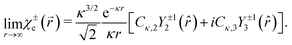 | (29) |
Eqn (67) and (68) in ref. 17 yield††| | 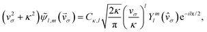 | (30) |
which we can apply to χεc to obtain| | 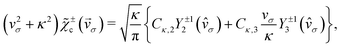 | (31) |
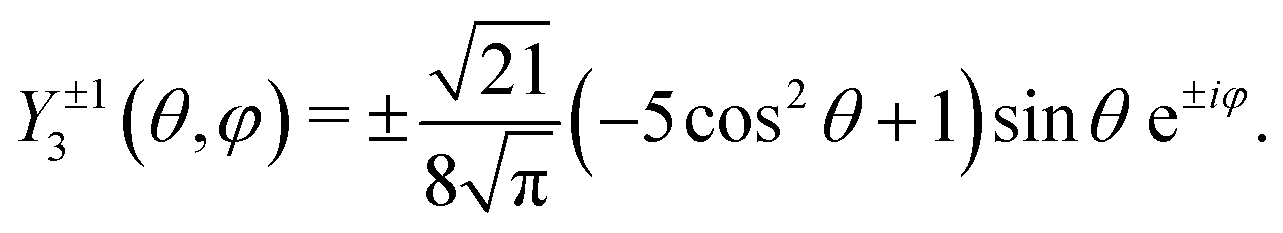
where we used the saddle point equation vσ2 = −κ2. The formulas for the spherical harmonics Y2±1(θ, φ) and Y3±1(θ, φ) are given by| |  | (32) |
| |  | (33) |
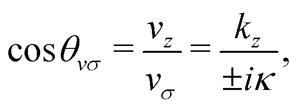
The polar angle of σ is defined through the equation‡‡
| |  | (34) |
which in turn implies that
| |  | (35) |
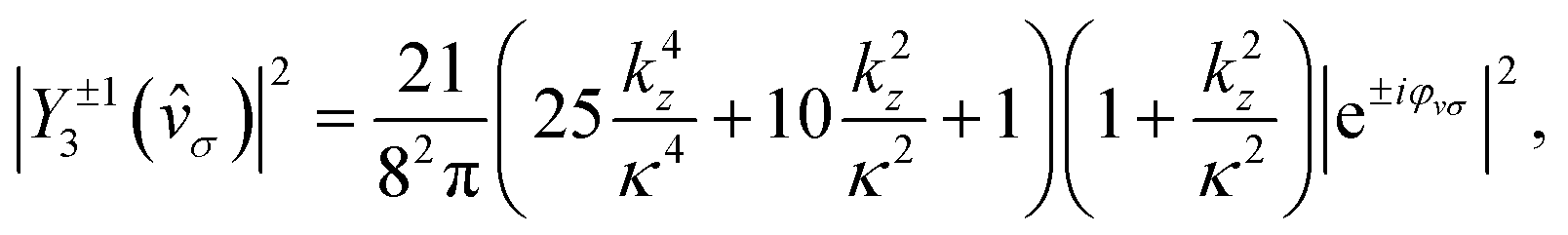
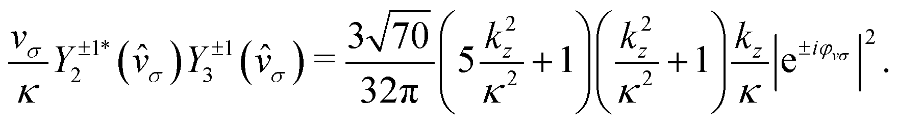
Using
eqn (32)–(35) one can show that
| |  | (36) |
| |  | (37) |
| |  | (38) |
Eqn (32)–(38) yield
eqn (14)–(17). Importantly, the FBA stems exclusively from the interference between the two components that make up
χεc,
i.e. from the real part of
eqn (38). It would vanish if the relative phase factor e
iη between these two components were ±1, which corresponds to the case where there is no probability current along the
z direction in the bound state (see states
χεp in ref.
12).
Now we proceed to the derivation of eqn (21). The expressions for χερ analogous to eqn (29), (31) and (14) read as
| |  | (39) |
| |  | (40) |
| |  | (41) |
Consider how the last expression changes if we rotate the initial wave function by an angle
α around the
z axis. From
eqn (3) it is evident that
| |  | (42) |
i.e. the wave function acquires an overall phase factor e
∓iα.
Eqn (41) now takes the form
| |  | (43) |
where only the terms in the last two lines depend on
α. Averaging over
α yields
eqn (21).
Acknowledgements
A. F. O. and O. S. gratefully acknowledge the MEDEA Project, which has received funding from the European Union's Horizon 2020 Research and Innovation Programme under the Marie Skłodowska-Curie Grant Agreement No. 641789. A. F. O. and O. S. gratefully acknowledge support from the DFG SPP 1840 “Quantum Dynamics in Tailored Intense Fields” and DFG Grant No. SM 292/5-2. A. F. O. gratefully acknowledges grants supporting his research at ICFO: Agencia Estatal de Investigación (the R&D project CEX2019-000910-S, funded by MCIN/AEI/10.13039/501100011033, Plan Nacional FIDEUA PID2019-106901GB-I00, FPI), Fundació Privada Cellex, Fundació Mir-Puig, Generalitat de Catalunya (AGAUR Grant No. 2017 SGR 1341, CERCA program), and EU Horizon 2020 Marie Skłodowska-Curie grant agreement No. 101029393.
Notes and references
- N. Koumura, R. W. J. Zijlstra, R. A. van Delden, N. Harada and B. L. Feringa, Nature, 1999, 401, 152–155 CrossRef CAS PubMed.
- A. F. Ordonez and O. Smirnova, Phys. Rev. A: At., Mol., Opt. Phys., 2018, 98, 063428 CrossRef CAS.
- B. Ritchie, Phys. Rev. A: At., Mol., Opt. Phys., 1976, 13, 1411 CrossRef.
- I. Powis, J. Chem. Phys., 2000, 112, 301–310 CrossRef CAS.
- N. Böwering, T. Lischke, B. Schmidtke, N. Müller, T. Khalil and U. Heinzmann, Phys. Rev. Lett., 2001, 86, 1187–1190 CrossRef PubMed.
- C. Lux, M. Wollenhaupt, T. Bolze, Q. Liang, J. Koehler, C. Sarpe and T. Baumert, Angew. Chem., Int. Ed., 2012, 51, 5001–5005 CrossRef CAS PubMed.
- L. Nahon, G. A. Garcia and I. Powis, J. Electron Spectrosc. Relat. Phenom., 2015, 204(Part B), 322–334 CrossRef CAS.
- I. Dreissigacker and M. Lein, Phys. Rev. A: At., Mol., Opt. Phys., 2014, 89, 053406 CrossRef.
- P. V. Demekhin, A. N. Artemyev, A. Kastner and T. Baumert, Phys. Rev. Lett., 2018, 121, 253201 CrossRef CAS PubMed.
- S. Beaulieu, A. Ferre, R. Geneaux, R. Canonge, D. Descamps, B. Fabre, N. Fedorov, F. Legare, S. Petit, T. Ruchon, V. Blanchet, Y. Mairesse and B. Pons, New J. Phys., 2016, 18, 102002 CrossRef.
- K. Fehre, S. Eckart, M. Kunitski, C. Janke, D. Trabert, J. Rist, M. Weller, A. Hartung, L. P. H. Schmidt, T. Jahnke, R. Dörner and M. Schöffler, J. Phys. Chem. A, 2019, 123, 6491–6495 CrossRef CAS PubMed.
- A. F. Ordonez and O. Smirnova, Phys. Rev. A: At., Mol., Opt. Phys., 2019, 99, 043416 CrossRef CAS.
- A. M. Perelomov, V. S. Popov and M. V. Terent'ev, Sov. Phys. JETP, 1966, 23, 924–934 Search PubMed.
-
H. A. Bethe and E. Salpeter, Quantum mechanics of one- and two-electron atoms, Springer Verlag, 1957 Search PubMed.
- I. Barth and O. Smirnova, Phys. Rev. A: At., Mol., Opt. Phys., 2011, 84, 063415 CrossRef.
- T. Herath, L. Yan, S. K. Lee and W. Li, Phys. Rev. Lett., 2012, 109, 043004 CrossRef PubMed.
- I. Barth and O. Smirnova, Phys. Rev. A: At., Mol., Opt. Phys., 2013, 87, 013433 CrossRef.
- S. Eckart, M. Kunitski, M. Richter, A. Hartung, J. Rist, F. Trinter, K. Fehre, N. Schlott, K. Henrichs and L. P. H. Schmidt,
et al.
, Nat. Phys., 2018, 14, 701 Search PubMed.
- S. Beiser, M. Klaiber and I. Y. Kiyan, Phys. Rev. A: At., Mol., Opt. Phys., 2004, 70, 011402 CrossRef.
- B. Bergues, Y. Ni, H. Helm and I. Y. Kiyan, Phys. Rev. Lett., 2005, 95, 263002 CrossRef PubMed.
- A. M. Perelomov, V. S. Popov and M. V. Terent'ev, Sov. Phys. JETP, 1967, 24, 207–217 Search PubMed.
- G. Gribakin and M. Y. Kuchiev, Phys. Rev. A: At., Mol., Opt. Phys., 1997, 55, 3760 CrossRef CAS.
- L. V. Keldysh, Sov. Phys. JETP, 1965, 20, 1307–1314 Search PubMed.
- J. Kaushal and O. Smirnova, Phys. Rev. A: At., Mol., Opt. Phys., 2013, 88, 013421 CrossRef.
- A. F. Ordonez and O. Smirnova, Phys. Rev. A: At., Mol., Opt. Phys., 2019, 99, 043417 CrossRef CAS.
- A. D. Müller, E. Kutscher, A. N. Artemyev and P. V. Demekhin, J. Chem. Phys., 2020, 152, 044302 CrossRef PubMed.
- J. Kaushal and O. Smirnova, J. Phys. B: At., Mol. Opt. Phys., 2018, 51, 174001 CrossRef.
-
N. Mayer, M. Ivanov and O. Smirnova, 2021, arXiv:2112.02658.
- Y. Huismans, A. Rouzée, A. Gijsbertsen, J. H. Jungmann, A. S. Smolkowska, P. S. W. M. Logman, F. Lépine, C. Cauchy, S. Zamith, T. Marchenko, J. M. Bakker, G. Berden, B. Redlich, A. F. G. van der Meer, H. G. Muller, W. Vermin, K. J. Schafer, M. Spanner, M. Y. Ivanov, O. Smirnova, D. Bauer, S. V. Popruzhenko and M. J. J. Vrakking, Science, 2011, 331, 61–64 CrossRef CAS PubMed.
- J. Kaushal and O. Smirnova, Phys. Rev. A: At., Mol., Opt. Phys., 2013, 88, 013421 CrossRef.
- L. Torlina, J. Kaushal and O. Smirnova, Phys. Rev. A: At., Mol., Opt. Phys., 2013, 88, 053403 CrossRef.
- J. Kaushal, F. Morales and O. Smirnova, Phys. Rev. A: At., Mol., Opt. Phys., 2015, 92, 063405 CrossRef.
- L. Torlina, F. Morales, J. Kaushal, I. Ivanov, A. Kheifets, A. Zielinski, A. Scrinzi, H. G. Muller, S. Sukiasyan and M. Ivanov,
et al.
, Nat. Phys., 2015, 11, 503–508 Search PubMed.
- L. Torlina and O. Smirnova, New J. Phys., 2017, 19, 023012 CrossRef.
- J. Kaushal and O. Smirnova, J. Phys. B: At., Mol. Opt. Phys., 2018, 51, 174001 CrossRef.
- D. Azoury, M. Krüger, B. D. Bruner, O. Smirnova and N. Dudovich, Sci. Rep., 2021, 11, 1–9 CrossRef PubMed.
- O. Smirnova, M. Spanner and M. Ivanov, Phys. Rev. A: At., Mol., Opt. Phys., 2008, 77, 033407 CrossRef.
Footnotes |
| † The anisotropy of the molecular potential is encoded in multipole terms higher than the monopole which decay rapidly with increasing distance to the parent ion. |
| ‡ In comparison to the notation used in ref. 17, we did the replacement χn(kz) → Xn(kz) in order to avoid confusion with the symbols χεc and χερ that we use here for the chiral wave functions. |
| § The emergence of a complex time ti in the theory results from the use of the saddle point approximation for the calculation of a time integral. |
| ¶ This follows from considering that the number of zeros of the radial part of the wave function is given by n − l − 1 and the convention of setting the radial wave function to be positive as r → 0. One can of course also use a different convention, but then the relative phases between the hydrogenic states in eqn (2) and (3) also have to be modified accordingly to keep the same density and probability currents discussed before. Our conclusions are independent from the convention. |
| || Note that the state χερ() is symmetric with respect to rotations by π around the y axis. |
| ** We will use the term “current” as a shorthand for “probability current density” and we will omit the 1/r2 scaling term in eqn (5). |
| †† In this appendix we will write vσ in place of vσ(ti)|k=kn for simplicity. |
| ‡‡ The ± in vσ = ±iκ comes from the saddle point equation vσ2 = −κ2 and is unrelated to the handedness ε = sgn(m) = ±1 of the initial state χεc and to the light polarization σ = ±1. |
|
| This journal is © the Owner Societies 2022 |
Click here to see how this site uses Cookies. View our privacy policy here. 
 Open Access Article
 This Open Access Article is licensed under a
  ab and
Olga
Smirnova
ab and
Olga
Smirnova
 . The states χερ and χεc are instances of the chiral-density and chiral-current families of hydrogenic chiral states introduced in ref. 12, respectively. The superscript ε = ± indicating the enantiomer simply corresponds to the sign of m, as can be seen in eqn (2)–(4). Opposite enantiomers (+ and −) are related to each other through a reflection in the y = 0 plane, which by definition is equivalent to a reversal of the sign of m used in the corresponding hydrogenic wave functions.
 , with opposite probability currents
 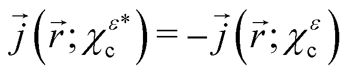 .
.
 , see eqn (2) and ref. 12. Left: Isosurfaces |χ+ρ(
 . The white arrows indicate the direction of the flow.
 cancel each other, PR1 determines which state, χεc or
  , dominates the photoelectron spectrum, and PR2 applied to the dominant state determines whether more electrons go forwards or backwards. As mentioned above, we know that PR1 is reversed when going from the one- to the many-photon regime, and we know the form of PR2 in the one-photon regime. In the many-photon regime, the adiabatic tunneling picture suggests that the photoelectron current along z will reflect that of the bound wave function under the barrier and in the vicinity of the tunnel exit, because of the continuity of the wave function χεc(
 across the exit of the tunnel. Since jz(
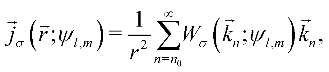
 is the amplitude of the vector potential, Ip is the ionization potential, and n0 is the minimum number of photons required for ionization in a strong field. Wσ(
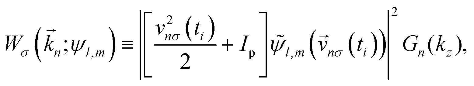
 is the wave function of the initial state in the momentum representation,

 is the Keldysh parameter.23 As expected from symmetry, this term behaves so that a reversal of the polarization σ is equivalent to a reversal of the azimuthal probability current of the bound state in the polarization plane sgn
 [eqn (3) and (4)] and from eqn (14)–(16), it follows that the PAD for the complex conjugated state
  reads
reads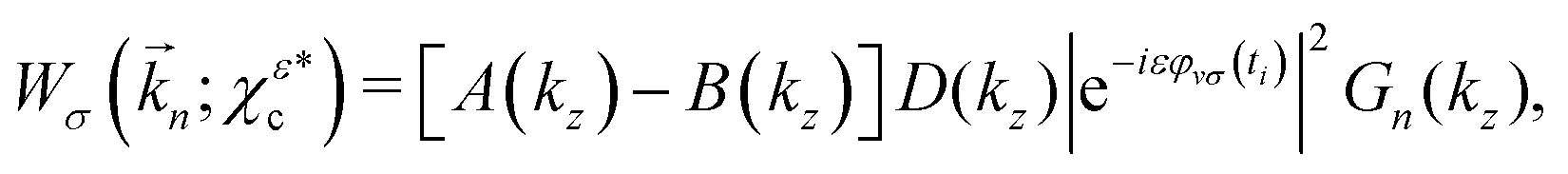
 yields a FBA exactly opposite to that of χεc.
 introduced in ref. 12, which instead of a probability current along z have probability density polarized along z (see Fig. 1 in ref. 12), do not display any FBA in the case of strong field of ionization.
 , one can show (see Appendix) that the PAD at energy k2n/2, averaged over the contributions of all initial state orientations related to the original orientation [eqn (2)] by a rotation Rz(α) of α radians around the z axis (as would be appropriate if the state is perfectly aligned along the z axis||), is given by the sum of the PADs for the states χεc* and
  [eqn (14) and (20)],
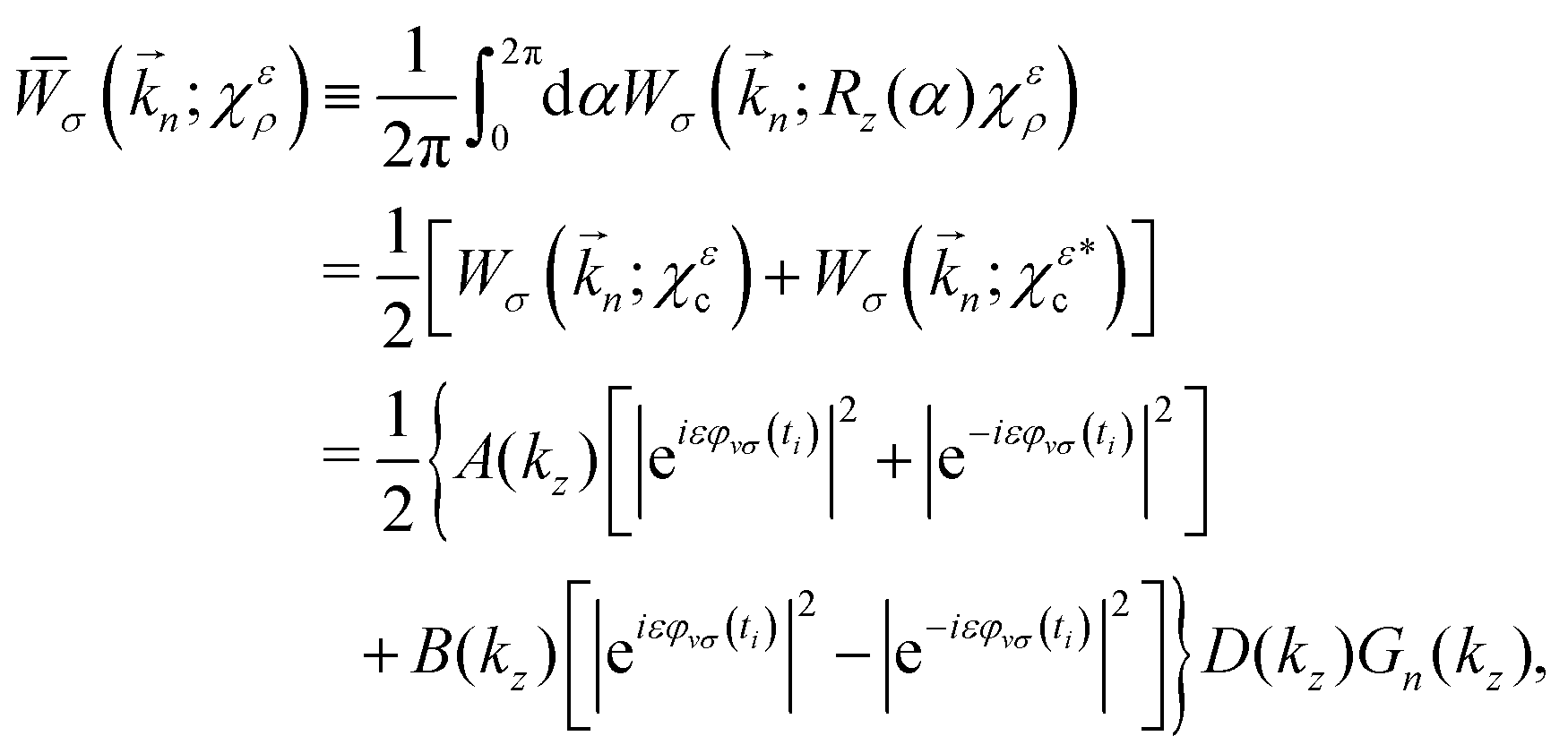
 , which have different angle-integrated yields for either opposite enantiomers or opposite circular polarizations, the angle-integrated photoelectron yield for the initial state χερ is independent of the enantiomer and circular polarization used. This is because the contribution from the second term in eqn (21) to the angle integrated yield vanishes and the first term in eqn (21) is explicitly symmetric with respect to a reversal of either polarization or enantiomer.
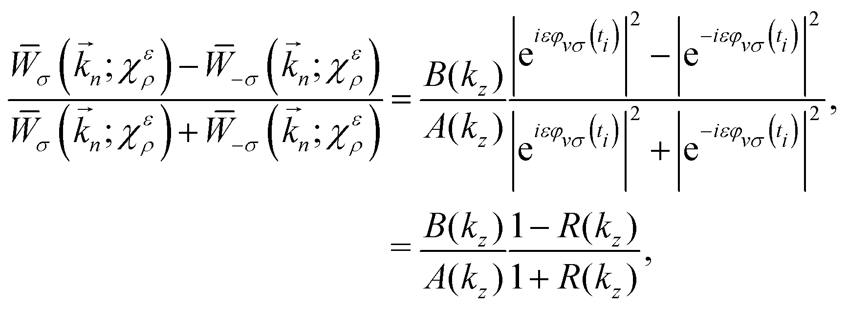
 , and χερ this means that only the part of Wσ involving A(kz) contributes to jσ,r and only the part of Wσ involving B(kz) contributes to jσ,z.
 corresponding to non-adiabiatic tunneling ionization. The results in Fig. 2 clearly show how the FBA is governed by the propensity rules discussed in Section 2. Panel (b) shows how for the states χεc, the direction of the net photoelectron current coincides with that of the bound probability current in the region close to the tunnel exit (vertical arrow), that is, where x2 + y2 ≫ 1 and |z| ≪ 1. We can also see to what extent the intensity of the photoelectron current is greater when the bound probability current (green circular arrow) and the electric field (red or blue circular arrows) circulate in opposite directions. Panel (c) of Fig. 2 shows the corresponding results for the initial state χερ. Although χερ does not display any bound probability currents, it yields a non-zero net photoelectron current along the z direction, consistent with its decomposition into χεc and
  . This decomposition along with the propensity rules for the χεc states dictate that the photoelectron current will flow in the direction corresponding to the χεc component that has a bound probability current counter-rotating with the electric field.
 , and χερ [eqn (2)–(4) and Fig. 1], via intense light circularly polarized in the xy plane. (a) Diagrams indicating the directions of the azimuthal component (green circular arrow) and the vertical component of the probability current in the region close to the tunnel exit (black vertical arrow) in the bound states χεc and
  . (b) Photoelectron current [eqn (7), (14), (20) and (24)] for different combinations of initial state [indicated according to (a)] and light polarization (red or blue circular arrow after the plus sign). Note that the direction of jz is determined by the direction of the vertical component of the bound current in the region close to the tunnel exit (black vertical arrow). Except for the high-momentum tail beyond k ≈ 1.5 a.u., the magnitude of jz is greater when the azimuthal bound probability current (green arrow) and the ionizing light (red or blue arrow) rotate in opposite directions. (c) Same as (b) but for the initial state χερ after averaging over the orientations of the initial state that result from a rotation around the z axis [eqn (7), (21) and (24)]. The state χερ is indicated with the two consecutive diagrams corresponding to its decomposition into states χεc and
  . In this case, jz is the average of the results obtained for each of its components in (b) [see eqn (21)]. The results shown are for a field of amplitude = 0.06 a.u. and frequency ω = 0.057 a.u., and for an ionization potential Ip = 0.5 a.u.
 [see eqn (2)–(4) and Fig. 2(a)], via intense light circularly polarized in the xy plane. Up to k ≈ 1.5 a.u. all the counter-rotating setups, where the azimuthal part of the bound probability current and the light rotate in opposite directions, yield a higher jr. Beyond k ≈ 1.5 a.u. the co-rotating setups yield a higher jr. The corresponding curve for the states χερ is simply the average between the two curves shown and is independent of enantiomer and light polarization. The parameters,