Photo-controlled exchange bias in CoO@Co–Fe PBA core–shell heterostructures†
Kangkang
Yao
a,
Jianing
Li
a,
Shuang
Yuan
 b,
Kaiyan
Cao
a,
Fang
Wang
c,
Yin
Zhang
 *a,
Fanghua
Tian
a,
Jinwen
Wang
 a,
Qiang
Wang
 b and
Sen
Yang
*a
aSchool of Physics, MOE Key Laboratory for Nonequilibrium Synthesis and Modulation of Condensed Matter, Xi'an Jiaotong University, Xi'an 710049, China. E-mail: yzhang18@xjtu.edu.cn; yang.sen@xjtu.edu.cn
bDepartment of New Energy Science & Engineering, School of Metallurgy, Northeastern University, Shenyang 110819, China
cKey Laboratory of Magnetic Molecules and Magnetic Information Materials, Ministry of Eduacation, Linfen 041004, China
First published on 23rd November 2021
Abstract
Regulating the exchange bias (EB) effect via an external field allows one to effectively tailor the properties of spin-valve-based spintronic devices. However, as a reliable way to manipulate the magnetic properties of materials, there have been few reports on the effect of light irradiation on the EB effect so far. In this work, a non-volatile light-tunable EB effect is achieved in a well-designed CoO and CoFe Prussian blue analogue core–shell structure (CoO@Co–Fe PBA), where the antiferromagnetic CoO has a large anisotropy, and the molecular magnet Co–Fe PBA is photosensitive. The EB field of this hybrid can be reduced by ∼50% after irradiation for 20 minutes, and the photo-induced change can be further increased by extending the irradiation time. In addition, the switching of the two EB effect states can be successfully implemented by switching red and blue light irradiation. Herein, this interesting photo-controlled EB effect is attributed to the change in the magnetization of the photosensitive Co–Fe PBA shell after light radiation, and the change is achieved by manipulating the number of FeIII–CoII magnetic pairs in the shell by incident light. Apparently, this striking light-controlled EB effect opens up new prospects for the design of new-generation optoelectronic devices.
1 Introduction
The exchange bias (EB) effect typically occurs in magnetic heterostructures at the interface of ferromagnetic (FM)/antiferromagnetic (AFM) structures, allowing the spins of FM layers to be stabilized via exchange coupling with adjacent AFM layers.1–5 This configuration enables the EB effect to play an important role in designing spin-valve type spintronic devices such as magnetic memory read heads, magnetic sensors, and magnetic random-access memories.6–8 Normally, tuning the EB effect through an external field (e.g. magnetic or electric field) is an effective route to realize the multifunctionality of the related spintronic devices. Very recently, special attention to the electric field controlled EB effect has been paid since the electric field controlled spintronic devices have the advantages of fast processing speed, high integration, and multiple functions.9–13 For example, Wu et al. realized the reversible switching between two different EB states by switching the ferroelectric polarization of BiFeO3 in a field effect device with multiferroic BiFeO3 employed as the dielectric and FM La0.7Sr0.3MnO3 as the conducting channel.9 In addition to the electric field, light irradiation is also a reliable approach to manipulate the magnetic properties of materials, ensuring non-contact, remote control, and low energy consumption, which are not available in other physical fields.14–20 Therefore, substituting light irradiation for the electric and magnetic fields to achieve EB effect modulation may facilitate the development of new multifunctional spintronic devices. However, only a few attempts have been made to obtain the light-controlled EB effect (e.g. IrMn/[Co/Pt],21 Fe2B/BiFeO3,22 and BiFeO3/La2/3Sr1/3MnO3/STO.23). For instance, the light-tuned EB effect was observed in BiFeO3/La2/3Sr1/3MnO3 thin films by Sung et al., which resulted from the reduction of the exchange coupling between Fe and Mn caused by the injection of electrons from the STO substrate.23 Even though the reported studies have laid the foundation for the light-controlled EB effect, some issues still remain poorly studied. First, continuous irradiation is a prerequisite for efficient tuning of the EB effect in the reported light-controlled EB systems. This dependence on continuous irradiation makes it energy-inefficient, unstable, and inconvenient to be used in spintronic devices. Moreover, currently, the light-controlled EB effect is only demonstrated in thin film systems composed of multilayer metal or metal oxide, which hinders the comprehensive understanding of this interesting phenomenon.Prussian blue analogs (PBA) with the spectacular non-volatile photo-induced magnetism effect are expected to solve the above-stated challenges based on a reasonable design.17,24–27 The photo-induced magnetism in PBAs is attributed to charge-transfer-induced spin transitions (CTISTs) mostly.17,28,29 For example, the FeII–CoIII diamagnetic pairs in the cobalt-iron cyanide AIxCo4[Fe(CN)6]y (Co–Fe PBA, AI is alkali ion) will transform into metastable FeIII–CoII magnetic pairs after light irradiation, due to the electron transfer from FeII to CoIII through the cyanide bridges.17 As a result, the magnetization and coercivity of Co–Fe PBA particles show a non-volatile increase at a macroscopic scale. Therefore, a rational design of the EB effect heterostructure with a photoactive PBA constituent would make the non-volatile light-controlled EB effect possible. In this regard, such heterostructures should be composed of FM or ferrimagnetic (FIM) PBA with photomagnetic effects and antiferromagnetic materials with large anisotropy. As a result, we can change the magnetism of PBA by illumination, which in turn modifies the exchange coupling between PBA and AFM, and finally, makes the vision of the light-tuned EB effect with memory effect a reality.
Driven by this idea, a core–shell heterostructure of the molecular magnet Co–Fe PBA and cobalt oxide (CoO) was designed and synthesized in this work. Herein, the FIM Co–Fe PBA was selected as the shell due to its non-volatile photomagnetic effect,17 and the AFM CoO served as the core component for its large magnetic anisotropy.1 A light-controlled EB effect was then demonstrated in the obtained core–shell heterostructure. Specifically, a period of light irradiation will lead to a noticeable reduction in the EB field (HEB) of the heterostructure. Besides, the magnitude of the reduction could be further controlled by tuning the illumination time. Moreover, two EB effect states could be also switched by alternating the wavelength of light irradiation (red and blue in this case). We attribute this striking photo-controlled EB effect to the generation of the photo-induced FeIII–CoII magnetic pairs in the Co–Fe PBA shell, the number of which can be controlled by the illumination time and wavelength of light. These results take the light-controlled EB effect forward an important step and supply facile ideas for the design of state-of-the-art spintronic devices.
2 Experimental section
In this work, all the chemicals were analytical grade reagents and used as received without further purification.Synthesis of CoO nanoparticles
In a typical reaction, cobalt acetate tetrahydrate (2 mmol) was dissolved in absolute ethanol (20 mL), after magnetic stirring for 30 min, and the solution was transferred to a Teflon lined stainless steel autoclave (50 mL capacity). Then the autoclave was kept at 150 °C for 24 h. After the autoclave was cooled down to room temperature, the brownish black insoluble solid products in ethanol were collected by centrifugation and washed with anhydrous ethanol several times. Finally, the spherical CoO particles were obtained after the products were air-dried at room temperature.Synthesis of CoO@Co–Fe PBA heterostructures
The synthesis of the core–shell structure was according to the previous report with modification.30 For the preparation of CoO@Co–Fe PBA, CoO (20 mg) synthesized in the previous step and potassium ferricyanide (80 mg) were added into deionized water (9.9 mL) in a three-necked flask. After 30 min of ultrasonic treatment, acetic acid solution (CH3COOH, 0.5 mL, 0.5 M) was added to the above solution, then the flask was transferred into a water bath and kept at 40 °C for 15 min. Finally, the CoO@Co–Fe PBA was obtained after centrifuging, washing, and air drying at room temperature.Characterization
The phase compositions of the prepared samples were examined via X-ray diffraction (XRD, Bruker D8 ADVANCE). The morphologies of the products were determined using a field emission scanning electron microscope (FE-SEM, GeminiSEM 500), and a transmission electron microscope (TEM, JEM-2100). The magnetic measurements were carried out on a SQUID (MPMS-squid VSM-094). For this, the powdered specimens were dissolved in polymethyl methacrylate transparent glue. And then the mixtures were fixed to the copper rod and put into the sample chamber of the SQUID. The field cooling magnetization curves were acquired at 200 Oe in the temperature range from 2 to 50 K. The hysteresis loops were measured under various maximum magnetic fields and cooling fields. The photo-induced magnetism measurements were performed through our homemade photomagnetic coupling devices. For this, focused LED light irradiation was introduced into the sample chamber of the SQUID through a fiber, and the illumination uniformity and the incident beam power on the sample were calibrated outside (I = 15 mW mm−2).3 Results and discussion
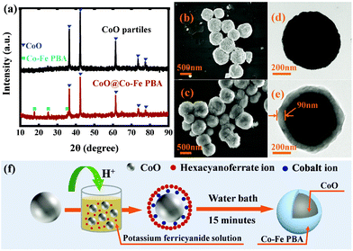
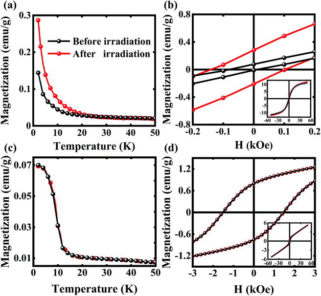
Fig. 1a shows the XRD patterns of the precursor CoO particles and the final CoO@Co–Fe PBA core–shell heterostructures. In accordance with standard PDF data (JCPDS#48-1719), no extraneous phases are observed in the CoO nanoparticles. In turn, the XRD spectrum of CoO@Co–Fe PBA evidences the presence of two distinct crystal structures. Except for the diffraction peaks of CoO, the residual peaks at 17.58°, 24.92°, and 30.91° agree with the patterns of Co–Fe PBA (JCPDS#-31-1000). As observed from the FE-SEM images (Fig. 1b and c), the size and morphology of the particles in the final product CoO@Co–Fe PBA are similar to those in the CoO precursor, disclosing their uniform distribution in both cases. Furthermore, compared to the TEM image of the precursor (Fig. 1d), the obvious contrast between the center and the edge region of the final product (Fig. 1e) reveals a well-defined core–shell structure, in which the Co–Fe PBA shells are about 90 nm in thickness. The specific synthesis process of the core–shell structure is illustrated in Fig. 1f. The CoO precursor must not only serve as a substrate for supporting Co–Fe PBA shells but also provide cobalt ions for the formation of Co–Fe PBA at the cost that its surface is dissolved by hydrogen ions.Fig. 2a displays the magnetization vs. temperature curves (M–T) of the CoO@Co–Fe PBA core–shell structure at H = 200 Oe before and after light irradiation in the field-cooling (FC) mode. To obtain the post-irradiation M–T curves, the sample was first field-cooled to the desired temperature, and then exposed to red light irradiation (λ = 635 nm) for 20 min. The M–T curve was measured from 2 to 50 K in the light off mode finally. As seen in Fig. 2a, the TC of the CoO@Co–Fe PBA hybrid is increased from 18 to 22 K after light radiation, and the magnetization is enhanced significantly in the entire temperature range below TC. The FC hysteresis loops (M–H), recorded at 2 K before and after light irradiation of the core–shell structure, are given in Fig. 2b. Similarly, for the M–H curves after lighting, the data were collected in the light off mode on the sample pre-exposed to 20 min of irradiation. The M–H curves before irradiation display a loop shift along the field axis, HEB = 35 Oe, and the coercivity (HC) of the CoO@Co–Fe PBA composite is 46 Oe. Interestingly, the HEB of the sample is reduced from 35 to 20 Oe after irradiation, while the HC increases from 46 to 130 Oe. For comparison, the M–T (Fig. 2c) and M–H curves (Fig. 2d) of the precursor CoO particles were measured as well. As seen, there is also a loop shift along the field axis (HEB = 34 Oe) for the CoO precursor, but different from the CoO@Co–Fe PBA hybrid, the M–T and M–H curves of the CoO precursor before and after irradiation completely overlap. We, therefore, argue that the light irradiation exerts no effect on the CoO particles, and based on this, it could be further inferred that the change of HEB in the CoO@Co–Fe PBA product is mainly caused by the alteration in the magnetic properties of the irradiated Co–Fe PBA shell. However, the HEB in CoO nanoparticles has the same order of magnitude as the value measured in the core–shell structure. This fact makes the mechanism of the EB in the core–shell structure ambiguous. To figure out this important question, we have measured both ZFC/FC curves for two samples. As seen in Fig. S1a (ESI†), there is a significant irreversibility between the FC and ZFC for the CoO precursor. In addition, shifting of the characteristic peak towards higher temperatures with an increase in the measured frequencies is observed in AC susceptibility as well. Apparently, these typical characteristics suggest the spin-glass behaviors of CoO nanoparticles in this case. Instead, the typical spin-glass features have disappeared in the core–shell structure from Fig. S1b (ESI†). Thus, it is believed that the EB effect of the CoO precursor is attributed to the presence of spin-glass, where the uncompensated spin formed on the CoO surface plays an important role.31–33 Obviously, this EB effect is different from that of the CoO@Co–Fe PBA hybrid, and it further explains why they show completely different responses to light irradiation.
To further understand the influence of lighting on the EB effect for the CoO@Co–Fe PBA core–shell structure, the dependence of HEB before and after irradiation on the maximum applied fields (Hmax) (Fig. S2, ESI†) and the cooling fields (HFC) (Fig. 3) was also measured. First, Fig. S2 (ESI†) shows that both the HEB and the vertical shift (denoted as Vshift in the inset) will decrease with the increase of Hmax, and the Vshift will almost vanish once the Hmax reaches ∼5 T. It indicates that the observed horizontal shift results from the exchange coupling in the sample rather than only from the insufficient measurement field. More importantly, as seen in Fig. 3, the HEB measured before irradiation increases with the HFC. Indeed, this is also direct evidence of the CoO–PBA (AFM-FIM) exchange coupling in the core–shell structure. It is noteworthy that the composite designed in this study is a heterostructure with TC(Co–Fe PBA) < TN(CoO). In this case, the FM layer is still in a PM state when the exchange coupling is established with the AFM layer, and the AFM layer is pinned by the induced magnetization in the PM layer.34, 35 Therefore, the HFC which causes the induced magnetization plays a crucial role at HEB when TC < TN. As expected, in this work, the bigger the HFC applied, the bigger the HEB obtained (Fig. 3). This behavior is obviously different from the behavior of HEB observed in the systems involving spin-glass types of phases, which usually shows a tendency of increasing first and then decreasing with the increase of HFC.36, 37 For comparison, the corresponding HEB values after light irradiation are shown in Fig. 3 with red solid circles. As seen, no matter how HFC changes, the light radiation will produce a significant decrease of HEB. For convenience, the ΔHE was defined as the difference between the exchange bias fields before and after light irradiation. Clearly, the ΔHE increased with the HFC.
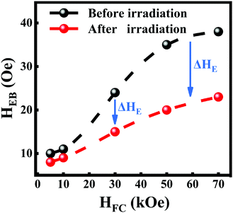 | ||
| Fig. 3 The HEB before and after red light irradiation under a series different cooling fields. The lines are guides to the eye. | ||
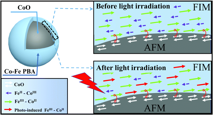
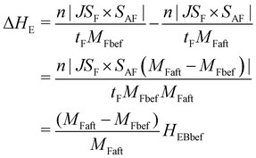
To interpret this striking change of HEB after irradiation, a schematic diagram of the present magnetic configuration before and after irradiation is drawn in Fig. 4. First of all, it is well known that the relative content of FeII–CoIII diamagnetic pairs and FeIII–CoII magnetic pairs in Co–Fe PBA is strongly dependent on the quantities of alkali cations introduced into the structure.38, 39 The FeII–CoIII diamagnetic pairs are necessary for the occurrence of the photomagnetic effect,38 whereas the FeIII–CoII magnetic pairs mainly contribute to the ferrimagnetism of the Co–Fe PBA shell at low temperatures.40 Due to the coexistence of photomagnetic and EB effects, the Co–Fe PBA shell of the present core–shell structure should contain FeII–CoIII diamagnetic pairs and FeIII –CoII magnetic pairs at the same time, as drawn in Fig. 4. When the CoO@Co–Fe PBA product is field-cooled to the desired temperature in the dark, the cooling field-induced magnetization of the FeIII–CoII magnetic pair will then establish an exchange coupling with part of the AFM surface spin, which is reflected in the HEB of the core–shell structure. As illustrated by the simplest model for explaining the EB phenomenon, the HEB can be expressed by the following equation:1
 | (1) |
 | (2) |
where HEBbef is the exchange bias field of the structure before light irradiation, MFbef and MFaft are the magnetizations of the shell before and after irradiation, respectively. According to this equation, the ΔHE should be positively linear with the HEB before light irradiation (HEBbef). And the HEBbef is also positively associated with HFC, so the ΔHE increases with the HFC. To verify this equation, the dependence of ΔHE measured in this work on HEBbef is plotted. As shown by the red line in Fig. S3 (ESI†), the ΔHE indeed appeared to have a clear positive linear correlativity with the HEBbef as predicted by the equation. Furthermore, the slope of this equation is calculated by substituting the measured MFbef and MFaft into the equation. Then the HEBbef is used as the independent variable to calculate the theoretical ΔHE (purple dashed line). Obviously, the theoretical results of ΔHE derived from this equation are in good agreement with the experimental results (the errors are less than 2 Oe). These further confirm the rationality of the proposed scheme that the modulation of the EB effect of the core–shell structure is realized through the control of magnetization of the PBA shell.
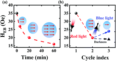
The above analysis revealed that the ability to change the magnetic properties of the Co–Fe PBA shell by irradiation plays a key role in the light-controlled EB effect of the whole core–shell structure. In addition, due to the possibility reported previously that the magnitude of the change in the magnetization of Co-Fe PBA can be further tuned by changing the parameter of incident light (e.g., illumination time,41 or light radiation wavelength.17,27), special attention is afterward paid to flexibly control the HEB through changing lighting conditions. Typically, the conversion rate for the Co–Fe PBA from the FeII–CoIII diamagnetic pair to a FeIII–CoII magnetic pair can be controlled by the illumination time: the longer the illumination time is, the higher the conversion rate is and the larger the magnetization is.41 Therefore, combined with our explanation, the HEB of the CoO@Co–Fe PBA core–shell structure is also believed to be further controlled by the illumination duration. As expected in Fig. 5a, the longer the composite is exposed to light irradiation, the smaller the HEB is obtained. However, it is obvious that a further increase in the light irradiation time above 20 minutes only led to a very slight change in the HEB. This was likely due to the fact that the rate of conversion of the FeII–CoIII diamagnetic pair into the FeIII–CoII magnetic pair attained its limit. In other words, the adjustable range of HEB is limited by the conversion rate of the FeII–CoIII diamagnetic pairs, and it may be increased by designing the PBA with a more spectacular photomagnetic effect as one of the components of the EB system. In addition, O. Sato et al. reported that the increased magnetization of the Co–Fe PBA triggered by red light could be partially offset by other irradiation with different wavelengths.17 This implies that the EB effect of the present CoO@Co–Fe PBA core–shell structures can be switched by altering the wavelengths of incident light. Therefore, a corresponding experiment was further conducted. Herein, the sample was first irradiated by red light for 20 minutes and followed by measuring the M–H curve immediately. Then we immediately irradiated the sample with blue light for another 20 minutes and then performed the M–H curve test again. As shown in Fig. 5b, the red light irradiation first reduces the HEB of the composite by increasing the amount of the photo-induced FeIII–CoII magnetic pairs.
And then the blue light irradiation (λ = 432 nm) partially offsets the effect of red light irradiation, slightly reduces the magnetization of the Co–Fe PBA shell, and then increases the HEB value accordingly. Herein, a comparative experiment was also carried out to ensure the light wavelength effect on HEB. Different from the previous test procedure, after the first measurement by red light irradiation, the sample was laid for 20 minutes under darkness instead of blue light irradiation. As shown by the triangle in Fig. 5b, after waiting for 20 minutes, the HEB measured again does not increase compared to the value after the red light irradiation. This result ensures the influence of blue light irradiation on the EB effect. Additionally, from the dependence of the reduction amplitude of HEB on the light irradiation time, it is believed that an appropriate increase of the blue light exposure duration is possible to recover the HEB more significantly. Apparently, these investigations demonstrated that the EB effect of such CoO@Co-Fe PBA hybrids could also be tailored by the parameters of incident light. It is believed that this work will be of great importance for understanding the mechanism of the photomagnetic effect, which will also promote potential applications in the field of spin electronics and optoelectronics.
4 Conclusions
In summary, we had demonstrated a facile photo-controlled exchange bias effect with a rational design of CoO@Co–Fe PBA core–shell heterostructures. The ability to tune the EB effect of this hybrid is simply achieved by light irradiation, and the photo-induced change of HEB is also dependent on the applied field and the cooling field. It is believed that this striking phenomenon is attributed to the formation of the photo-induced FeIII–CoII magnetic pairs in the FIM Co–Fe PBA shell. In addition, the value of HEB can be further regulated accurately by setting the irradiation time or adjusting the incident light frequency. In the future, expanding the tunable range and increasing the working temperature of such materials should be mainly considered, which is of important significance for increasing the practicality of this light-controlled EB effect.Conflicts of interest
There are no conflicts to declare.Acknowledgements
This work was supported by the National Natural Science Foundation of China (Grant No. 52071255, 91963111 and 51801145), the Key Scientific and Technological Innovation Team of Shaanxi province (2020TD-001), the Liao Ning Revitalization Talents Program (Grant No. XLYC1807214), the Fundamental Research Funds for the Central Universities (China), the World-Class Universities (Disciplines) and the Characteristic Development Guidance Funds for the Central Universities. We also appreciate Dr Chang Huang's help in XRD analysis at Instrument Analysis Center of Xian Jiaotong University.Notes and references
- W. H. Meiklejohn and C. P. Bean, Phys. Rev., 1957, 105, 904–913 CrossRef CAS.
- J. Nogués, J. Sort, V. Langlais, V. Skumryev, S. Suriñach, J. S. Muñoz and M. D. Baró, Phys. Rep., 2005, 422, 65–117 CrossRef.
- W. Zhang and K. M. Krishnan, Mater. Sci. Eng., R, 2016, 105, 1–20 CrossRef.
- M. Gruber, F. Ibrahim, S. Boukari, H. Isshiki, L. Joly, M. Peter, M. Studniarek, V. D. Costa, H. Jabbar and V. Davesne, Nat. Mater., 2015, 14, 981 CrossRef CAS PubMed.
- T. Blachowicz and A. Ehrmann, Coatings, 2021, 11, 122 CrossRef CAS.
- S. Parkin, X. Jiang, C. Kaiser, A. Panchula, K. Roche and M. Samant, Proc. IEEE, 2003, 91, 661–680 CrossRef CAS.
- A. Moser, K. Takano, D. T. Margulies, M. Albrecht, Y. Sonobe, Y. Ikeda and S. H. Sun, J. Phys. D: Appl. Phys., 2002, 35, R157–R167 CrossRef CAS.
- S. S. P. Parkin, K. P. Roche, M. G. Samant, P. M. Rice, R. B. Beyers, R. E. Scheuerlein, E. J. O'Sullivan, S. L. Brown, J. Bucchigano, D. W. Abraham, Y. Lu, M. Rooks, P. L. Trouilloud, R. A. Wanner and W. J. Gallagher, J. Appl. Phys., 1999, 85, 5828–5833 CrossRef CAS.
- S. M. Wu, S. A. Cybart, P. Yu, M. D. Rossell, J. X. Zhang, R. Ramesh and R. C. Dynes, Nat. Mater., 2010, 9, 756–761 CrossRef CAS PubMed.
- V. Laukhin, V. Skumryev, X. Martí, D. Hrabovsky, F. Sánchez, M. V. García-Cuenca, C. Ferrater, M. Varela, U. Lüders, J. F. Bobo and J. Fontcuberta, Phys. Rev. Lett., 2006, 97, 227201 CrossRef CAS PubMed.
- P. Borisov, A. Hochstrat, X. Chen, W. Kleemann and C. Binek, Phys. Rev. Lett., 2005, 94, 117203 CrossRef.
- Y.-C. Lau, D. Betto, K. Rode, J. M. D. Coey and P. Stamenov, Nat. Nanotechnol., 2016, 11, 758–762 CrossRef CAS.
- K. Zhang, Y. L. Cao, Y. W. Fang, Q. Li and L. Mei, Nanoscale, 2015, 7, 6334 RSC.
- C. R. Gros, M. K. Peprah, B. D. Hosterman, T. V. Brinzari, P. A. Quintero, M. Sendova, M. W. Meisel and D. R. Talham, J. Am. Chem. Soc., 2014, 136, 9846–9849 CrossRef CAS.
- V. Pinchetti, Q. Di, M. Lorenzon, A. Camellini, M. Fasoli, M. Zavelani-Rossi, F. Meinardi, J. Zhang, S. A. Crooker and S. Brovelli, Nat. Nanotechnol., 2018, 13, 145–151 CrossRef CAS.
- S.-I. Ohkoshi, H. Tokoro, T. Hozumi, Y. Zhang, K. Hashimoto, C. Mathonière, I. Bord, G. Rombaut, M. Verelst, C. Cartier Dit Moulin and F. Villain, J. Am. Chem. Soc., 2006, 128, 270–277 CrossRef CAS.
- O. Sato, T. Iyoda, A. Fujishima and K. Hashimoto, Science, 1996, 272, 704–705 CrossRef CAS PubMed.
- R. W. Teale and D. W. Temple, Phys. Rev. Lett., 1967, 19, 904–905 CrossRef CAS.
- M. M. Paquette, D. Plaul, A. Kurimoto, B. O. Patrick and N. L. Frank, J. Am. Chem. Soc., 2018, 140, 14990–15000 CrossRef CAS.
- L.-Z. Cai, Q.-S. Chen, C.-J. Zhang, P.-X. Li, M.-S. Wang and G.-C. Guo, J. Am. Chem. Soc., 2015, 137, 10882–10885 CrossRef CAS PubMed.
- P. Vallobra, T. Fache, Y. Xu, L. Zhang, G. Malinowski, M. Hehn, J.-C. Rojas-Sánchez, E. E. Fullerton and S. Mangin, Phys. Rev. B, 2017, 96, 449 CrossRef.
- A. Aftabi and M. M. Tehranchi, J. Alloys Compd., 2018, 766, 1054–1060 CrossRef CAS.
- K. D. Sung, T. K. Lee, Y. A. Park, N. Hur and J. H. Jung, Appl. Phys. Lett., 2014, 104, 252407 CrossRef.
- D. M. Pajerowski, M. J. Andrus, J. E. Gardner, E. S. Knowles, M. W. Meisel and D. R. Talham, J. Am. Chem. Soc., 2010, 132, 4058–4059 CrossRef CAS PubMed.
- J.-D. Cafun, G. Champion, M.-A. Arrio, C. Cartier Dit Moulin and A. Bleuzen, J. Am. Chem. Soc., 2010, 132, 11552–11559 CrossRef CAS.
- Y. Moritomo, M. Hanawa, Y. Ohishi, K. Kato, M. Takata, A. Kuriki, E. Nishibori, M. Sakata, S. Ohkoshi, H. Tokoro and K. Hashimoto, Phys. Rev. B, 2003, 68, 1554 Search PubMed.
- S.-i. Ohkoshi and H. Tokoro, Acc. Chem. Res., 2012, 45, 1749–1758 CrossRef CAS.
- M. Cammarata, S. Zerdane, L. Balducci, G. Azzolina, S. Mazerat, C. Exertier, M. Trabuco, M. Levantino, R. Alonso-Mori, J. M. Glownia, S. Song, L. Catala, T. Mallah, S. F. Matar and E. Collet, Nat. Chem., 2021, 13, 10–14 CrossRef CAS PubMed.
- S. F. Jafri, E. S. Koumousi, M.-A. Arrio, A. Juhin, D. Mitcov, M. Rouzières, P. Dechambenoit, D. Li, E. Otero, F. Wilhelm, A. Rogalev, L. Joly, J.-P. Kappler, C. Cartier Dit Moulin, C. Mathonière, R. Clérac and P. Sainctavit, J. Am. Chem. Soc., 2019, 141, 3470–3479 CrossRef CAS PubMed.
- F.-X. Bu, L. Xu, W. Zhang, C.-Y. Jin, R.-J. Qi, R. Huang and J.-S. Jiang, Chem. Commun., 2015, 51, 6198–6201 RSC.
- X. He and H. Shi, Mater. Res. Bull., 2011, 46, 1692–1697 CrossRef CAS.
- H. T. Zhang and X. H. Chen, J. Phys. Chem. B, 2006, 110, 9442–9447 CrossRef CAS.
- T. Ambrose and C. L. Chien, Phys. Rev. Lett., 1996, 76, 1743–1746 CrossRef CAS.
- G. Salazar-Alvarez, J. Sort, S. Suriñach, M. D. Baró and J. Nogués, J. Am. Chem. Soc., 2007, 129, 9102–9108 CrossRef CAS PubMed.
- J. W. Cai, K. Liu and C. L. Chien, Phys. Rev. B, 1999, 60, 72–75 CrossRef CAS.
- L. D. Bianco, D. Fiorani, A. M. Testa, E. Bonetti and L. Signorini, Phys. Rev. B, 2004, 70, 052401 CrossRef.
- H. Wang, T. Zhu, K. Zhao, W. N. Wang, C. S. Wang, Y. J. Wang and W. S. Zhan, Phys. Rev. B, 2004, 70, 2516–2528 Search PubMed.
- A. Bleuzen, C. Lomenech, V. Escax, F. Villain, F. Varret, C. Cartier Dit Moulin and M. Verdaguer, J. Am. Chem. Soc., 2000, 122, 6648–6652 CrossRef CAS.
- V. Escax, A. Bleuzen, C. Cartier Dit Moulin, F. Villiam, A. Goujon, F. Varret and M. Verdaguer, J. Am. Chem. Soc., 2001, 123, 12536–12543 CrossRef CAS PubMed.
- G. Champion, V. Escax, C. Cartier Dit Moulin, A. Bleuzen, F. Villain, F. Baudelet, E. Dartyge and M. Verdaguer, J. Am. Chem. Soc., 2001, 123, 12544–12546 CrossRef CAS.
- C. Cartier Dit Moulin, F. Villain, A. Bleuzen, M.-A. Arrio, P. Sainctavit, C. Lomenech, V. Escax, F. Baudelet, E. Dartyge, J.-J. Gallet and M. Verdaguer, J. Am. Chem. Soc., 2000, 122, 6653–6658 CrossRef CAS.
Footnote |
| † Electronic supplementary information (ESI) available. See DOI: 10.1039/d1tc04562h |
| This journal is © The Royal Society of Chemistry 2022 |

