Low-temperature synthesis of a carbon nanocage saturable absorber for pulsed erbium-doped fiber laser generation
Xintong
Xu
ab,
Jiaqi
Chen
ab,
Lang
Sun
ab,
Shaowen
Chu
ab,
Dalin
Sun
ab,
Juan
Lu
a,
Dingdi
Wang
c and
Shuangchen
Ruan
 *ab
*ab
aCollege of New Materials and New Energies, Shenzhen Technology University, Shenzhen, 518118, China
bShenzhen Key Laboratory of Laser Engineering, Shenzhen University, Shenzhen, 518060, China. E-mail: scruan@sztu.edu.cn
cDepartment of Chemistry, Northwestern University, Evanston, IL 60208, USA
First published on 26th November 2021
Abstract
Exploring a new photonic material with low preparation cost, good optical stability and nonlinearity at the near-infrared waveband is important for ultrafast optical science and devices. Here, with a relatively low carbonization temperature (350, 400, and 450 °C), carbon nanocages (CNCs) are synthesized by pyrolyzing ethylenediamine trapped inside the zeolite ZnAlPO-12 template. It is found that the nonlinear saturable absorption properties of the as-synthesized CNCs are highly dependent on the fabrication temperature. The modulation depth of the CNCs can be decreased from 45% to 35.2% by increasing the fabrication temperature from 350 °C to 450 °C. By incorporating the CNC-based SAs that were fabricated under different temperatures into an erbium-doped fiber laser cavity, either Q-switching or mode-locking with high operational stability can be obtained in the same fiber laser cavity. To the best of our knowledge, this is the first demonstration of a CNC-based SA to achieve a pulsed fiber laser, which proves the excellent nonlinear optical properties of the CNCs and lays a foundation for their development in photonic devices.
1. Introduction
Pulsed fiber lasers have wide applications in the field of optical communications, sensors, biomedical diagnostics, and industrial fabrications due to their compactness, high beam quality, and good stability.1–5 Generally, Q-switching or mode-locking based on a saturable absorber (SA) are used for pulsed laser generation. A SA is a kind of nonlinear optical material that can act as a passive optical switch to modify the laser continuous-wave output into a train of optical pulses.6–10 As a type of SA, semiconductor SA mirrors (SESAMs) have been widely used in commercial laser systems due to their large modulation depth and low saturable intensity.11–13 However, SESAMs have some drawbacks, such as a complex synthesis process, high cost, and a narrow saturable absorption band. Recently, low-dimensional materials, such as graphene,14–19 carbon nanotubes,20–24 graphdiyne,25 transition metal dichalcogenides (TMDCs),26–28 topological insulators,29–35 and black phosphorus (BP), have gained rapid development for pulsed laser generation due to their tunable modulation depth, ultrafast carrier dynamics and large third order optical nonlinearity.36,37 However, there are many challenges associated with these low-dimensional material SAs for photonics devices. For example, the modulation depth of graphene is relatively low, leading to it being unsuitable for high-power fiber lasers. For carbon nanotubes and graphdiyne, the nonsaturable absorption loss is relatively high, leading to a low pump power slope efficiency of the fiber laser. As for the TMDCs and topological insulators, the fabrication stability with high reproducibility needs to be highly improved for real application in a fiber laser. As for the BP, much effort is needed to improve its stability in the ambient environment. Thus, it is of great importance to explore new materials with fascinating nonlinear optical parameters, good stability, and low cost for photonics devices.38–44As a new class of carbon nanomaterials, carbon nanocages (CNCs) of sp2 hybridization have been developed for many applications due to their unique features, including large specific surface area, high conductivity, and defective surface texture.45–47 For example, CNCs have been widely used as the electrode materials for batteries and supercapacitors.48–51 Moreover, CNCs can be used as the metal-free electrocatalysts for energy conversion reactions, including the oxygen reduction reaction and lithium polysulfide conversions in lithium–sulfur batteries.52–54 Although CNCs have been applied in diverse areas, their nonlinear saturable absorption properties and applications in photonic devices have not been investigated and reported.
In this paper, we have demonstrated the fabrication of CNCs using zeolite ZnAlPO-12 as a template by pyrolyzing ethylenediamine (EDA) at a relatively low carbonization temperature and the application of CNCs as a new type of SA for ultrafast photonics. The as-synthesized CNCs are composited with polyvinyl alcohol (PVA) to form a CNCs/PVA film. By inserting the CNCs/PVA film into the erbium-doped fiber laser cavity, either the Q-switching or mode-locking pulsed fiber laser can be obtained. The CNC SA has the advantages of being cost-effective, controllable nonlinear optical properties, long-term operation stability and relatively high optical damage threshold, suggesting the potential application of CNCs in the fields of nonlinear optics and ultrafast photonics.
2. Fabrication and characterization of the CNC-based SA
Generally, the fabrication of CNCs can be divided into the following three steps. Firstly, the zeolite ZnAlPO-12 crystals are synthesized by using the hydrothermal method.55,56 As one of the wet-chemical methods, the hydrothermal method is widely used for the synthesis of zeolites. In hydrothermal conditions, the effective solvation ability of water and the solubility of the reactants can be highly enhanced. Moreover, the reactivity of the source materials can be greatly activated. Thus, the hydrothermal method is an efficient synthetic strategy for the synthesis of zeolite ZnAlPO-12. The aluminum, zinc, and phosphorus sources were aluminum tri-isopropoxide, zinc acetate, and orthophosphoric acid, respectively. EDA was used as the structure-directing agent. The reaction mixture with a molar ratio of 0.8ZnO![[thin space (1/6-em)]](https://www.rsc.org/images/entities/char_2009.gif) :
:![[thin space (1/6-em)]](https://www.rsc.org/images/entities/char_2009.gif) Al2O3
Al2O3![[thin space (1/6-em)]](https://www.rsc.org/images/entities/char_2009.gif) :
:![[thin space (1/6-em)]](https://www.rsc.org/images/entities/char_2009.gif) P2O5
P2O5![[thin space (1/6-em)]](https://www.rsc.org/images/entities/char_2009.gif) :
:![[thin space (1/6-em)]](https://www.rsc.org/images/entities/char_2009.gif) 2.3EDA
2.3EDA![[thin space (1/6-em)]](https://www.rsc.org/images/entities/char_2009.gif) :
:![[thin space (1/6-em)]](https://www.rsc.org/images/entities/char_2009.gif) 500H2O was obtained and heated under hydrothermal pressure at 170 °C in a Teflon-lined stainless autoclave for 40 h. Subsequently, the obtained zeolite ZnAlPO-12 crystals were placed into a quartz boat and carbonized at the designated temperature of 350, 400, and 450 °C under continuous nitrogen flow. Finally, in order to efficiently remove the ZnAlPO-12 template, the obtained carbonized samples were dissolved in 2 M NaOH aqueous solution followed by ultrasonic treatment within concentrated HCl at room temperature. Thus, our synthesis procedure is quite simple and inexpensive, and can be readily scaled up for practical applications requiring bulk quantities of carbon nanocages.
500H2O was obtained and heated under hydrothermal pressure at 170 °C in a Teflon-lined stainless autoclave for 40 h. Subsequently, the obtained zeolite ZnAlPO-12 crystals were placed into a quartz boat and carbonized at the designated temperature of 350, 400, and 450 °C under continuous nitrogen flow. Finally, in order to efficiently remove the ZnAlPO-12 template, the obtained carbonized samples were dissolved in 2 M NaOH aqueous solution followed by ultrasonic treatment within concentrated HCl at room temperature. Thus, our synthesis procedure is quite simple and inexpensive, and can be readily scaled up for practical applications requiring bulk quantities of carbon nanocages.
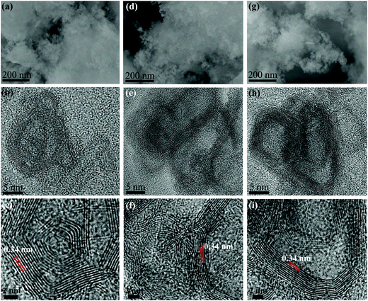
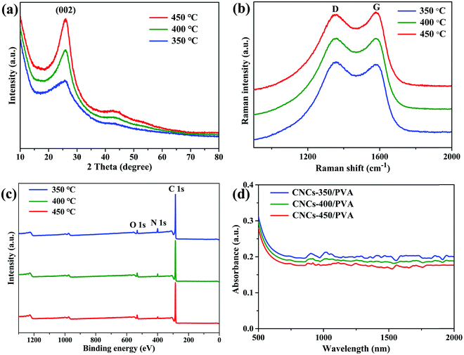
The CNCs that were obtained at the carbonization temperature of 350, 400, and 450 °C are denoted as CNCs-350, CNCs-400, and CNCs-450, respectively. Fig. 1(a), (d) and (g) show the scanning electron microscopy (SEM) images of the CNCs-350, CNCs-400 and CNCs-450, respectively. All samples have the appearance of a cotton like morphology with interconnected structures. Fig. 1(b), (e) and (h) show the corresponding high-resolution transmission electron microscopy (HRTEM) images of the CNCs. By increasing the carbonization temperature, the graphitic layers inside the nanocage become more ordered. In addition, the size of the CNCs becomes larger and the walls become thicker. All cages have the layer distance of 0.34 nm, as shown in Fig. 1(c), (f) and (i). Fig. 2(a) shows the powder X-ray diffraction (XRD) of the CNCs under different carbonization temperatures. The peak intensity around 26° that corresponds to the periodically arranged (002) increases by increasing the carbonization temperature from 350 to 450 °C, indicating the enhanced crystallinity of the CNCs. Raman spectroscopy also demonstrates the enhanced ordering of the CNCs due to the decreased intensity ratio of the D-band (1350 cm−1) to G-band (1590 cm−1) on increasing the carbonization temperature (Fig. 2b). In addition, the chemical composition of the as-synthesized CNCs was investigated by X-ray photoelectron spectroscopy (XPS) measurements. All samples show three peaks at 284.8, 400 and 532 eV, indicating the presence of C, N and O elements without any other impurities (Fig. 2c). As the carbonization temperature was increased from 350 to 450 °C, the content of N decreased from 8.2 at% to 1.6 at% for the breaking of the C–N bonds at high temperatures. Then, the as-synthesized CNCs were composited with polyvinyl alcohol (PVA) to form the film.57Fig. 2(d) shows the linear optical absorption of the CNCs/PVA samples. All samples have a broad absorption band, including the 1.5 μm wavelength band.
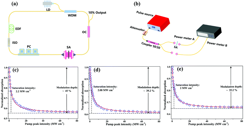
The nonlinear optical property of the CNCs/PVA was characterized via a balanced twin detector measurement using a home-made 1.5 μm probe laser with the pulse width of 800 fs and the repetition rate of 23 MHz, as shown in Fig. 3(b). The data for normalized absorption were then fitted according to a simple two-level SA model with formula:24,58α(I) = α0 × (1 + I/Isat) + αns [α(I): intensity-dependent absorption coefficient, α0: saturable absorption, I: input intensity, Isat: saturation power intensity, αns: non-saturable absorption]. Based on the fitting results, the modulation depth and saturable intensity of CNCs-350/PVA at 1.5 μm are determined to be 45% and 2.2 MW cm−2, respectively [Fig. 3(c)]. As for the CNCs-400/PVA, the modulation depth and saturable intensity at 1.5 μm are determined to be 39.2% and 2.08 MW cm−2, respectively [Fig. 3(d)]. As for the CNCs-450/PVA, the modulation depth and saturable intensity at 1.5 μm are determined to be 35.2% and 2 MW cm−2, respectively [Fig. 3(e)]. The non-saturable loss of CNC-350/PVA, CNC-400/PVA, and CNC-450/PVA SA is about 55%, 60.8%, and 64.8%, respectively. In our case, the contributions to the non-saturable losses may include the linear coupling loss between fiber ends and the refraction and absorption from the polymer matrix.20
3. Experimental setup and results
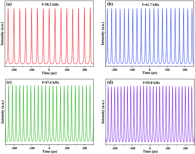
To reveal the applicability of the CNCs/PVA in pulsed fiber laser generation, a ring erbium-doped fiber laser (EDFL) cavity was constructed, as shown in Fig. 3(a). Highly erbium-doped fiber (EDF) with a length of 0.8 m was used as a gain medium. A 976 nm laser diode (LD) was used as a pump source and coupled into the cavity through a 980/1550 nm wavelength-division multiplexer (WDM). A polarization controller (PC) was used to adjust the polarization state, and a polarization independent isolator (ISO) was used to ensure unidirectional operation of the ring cavity. The total cavity length was about 11 m, and a 10% fiber coupler was used to output the laser. The output lasers were analyzed by using a power meter, an autocorrelator, an optical spectrum analyzer with a resolution of 0.02 nm, and a real time oscilloscope with a bandwidth of 4 GHz combined with a 12.5 GHz photo-detector, respectively.Before inserting the CNCs/PVA SA into the laser cavity, the laser was always worked in the continuous-wave operation by varying the pump power over the entire range and adjusting the polarization state. Then, the CNCs-350/PVA composite film SA was placed between two fiber connectors to integrate into the EDFL ring cavity. When the pump power increased to 90 mW, the operation of Q-switching pulses was obtained [Fig. 4(a)]. The repetition rate of Q-switching gradually increases as the pump power increases, which is the typical feature of a passively Q-switching fiber laser [Fig. 4(b–d)]. Moreover, the output pulse trains were kept stable with uniform intensity distribution by increasing the pump power, indicating the highly stable Q-switching EDFL.
Fig. 5 summarizes the typical Q-switching operation state at a pump power of 240 mW. Fig. 5(a) shows the typical Q-switching pulse train. It has a repetition rate of 62.5 kHz. The center wavelength is at 1568.6 nm and the 3 dB bandwidth is about 0.58 nm, as shown in Fig. 5(b). The corresponding pulse duration is about 2.9 μs [Fig. 5(c)]. Fig. 5(d) shows the output power of the Q-switching EDFL as a function of the pump power. By increasing the pump power from 90 to 240 mW, the output power increases almost linearly from 0.2 to 7.78 mW, resulting in a slope efficiency of 4.9%. The maximum pulsed energy of this Q-switching EDFL is about 124.5 nJ. To estimate the optical damage threshold of the CNCs-350/PVA SA, we increased the pump power to 500 mW (the maximum output power of the pump source that we used) and left it for 3 hours. Then, by decreasing the pump power from 500 to 0 mW, we found that the stable Q-switching EDFL can be obtained again in the range of 90 to 240 mW. Thus, the optical damage threshold of the CNCs-350/PVA SA is over 500 mW.
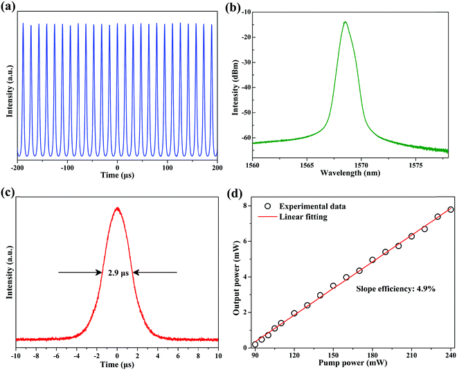 | ||
| Fig. 5 Typical characteristics of Q-switching EDFL. (a) Output pulse train. (b) Emission spectrum. (c) Single pulse profile. (d) Output power as a function of pump power. | ||
Interestingly, the stable Q-switching EDFL can also be obtained by inserting the CNCs-400/PVA composite film SA into the cavity. Fig. 6 summarizes the typical Q-switching operation state at the pump power of 220 mW. Fig. 6(a) shows the typical Q-switching pulse train. It has a repetition rate of 58.5 kHz. The center wavelength is at 1569.3 nm and the 3 dB bandwidth is about 0.87 nm, as shown in Fig. 6(b). The corresponding pulse duration is about 3.3 μs [Fig. 6(c)]. Fig. 6(d) shows the output power of the Q-switching EDFL as a function of the pump power. By increasing the pump power from 76 to 220 mW, the output power increases almost linearly from 0.18 to 7.39 mW, resulting in a slope efficiency of 5%. The maximum pulsed energy of this Q-switching EDFL is about 126.3 nJ.
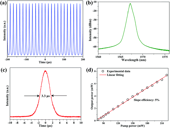 | ||
| Fig. 6 Typical characteristics of Q-switching EDFL. (a) Output pulse train. (b) Emission spectrum. (c) Single pulse profile. (d) Output power as a function of pump power. | ||
Many investigations have been reported that the operation state (Q-switching or mode-locking) of fiber lasers highly depends on the saturable absorption parameters of the saturable absorber.59–61 There is a critical parameter: E2 = EGESAΔT, where EG, ESA, and ΔT are the gain saturation energy, saturation energy, and SA modulation depth, respectively. The continuous wave mode-locking can be achieved when the single pulse energy EP in the fiber laser cavity satisfies EP > E2. Thus, the value of E needs to be highly depressed to fulfill the mode-locking operation state. In our fiber laser cavity, the gain saturation energy EG is fixed by the gain fiber. The only effective way that can decrease E is ESA and ΔT by adjusting the nonlinear optical property of carbon nanocages. Depending on the fabrication temperature, the modulation depth and saturation intensity of CNCs-350/PVA are 45% and 2.2 MW cm−2, respectively. In addition, the modulation depth and saturation intensity of CNCs-400/PVA SA are 39.2% and 2.08 MW cm−2, respectively. In both cases, the value of E is not small enough to satisfy the mode-locking conditions in this fiber laser cavity.
As expected, by incorporating the CNCs-450/PVA composite film SA with relatively low modulation depth into the cavity, mode-locking operation of the EDFL was fulfilled when the pump power reached 66 mW. The emission spectrum of the above mode-locking EDFL has obvious Kelly spectral sidebands, indicating that the mode-locking fiber laser is operating in the soliton regime [Fig. 7(a)]. It possesses a center wavelength of 1565.9 nm and 3 dB spectral bandwidth of 4.48 nm. Fig. 7(b) shows an 18.1 MHz repetition rate of the mode-locking pulse train (period τ = 55.2 ns), which matches well with the laser cavity length (11 m). The pulse duration is about 638 fs, assuming a sech2 pulse profile, as shown in Fig. 7(c). Fig. 7(d) shows the corresponding radio frequency (RF) spectrum. The signal-to-noise ratio (SNR) is up to 68 dB and higher than that in other research using nanomaterials as the SA, indicating a good mode-locking stability.9,14,25,62
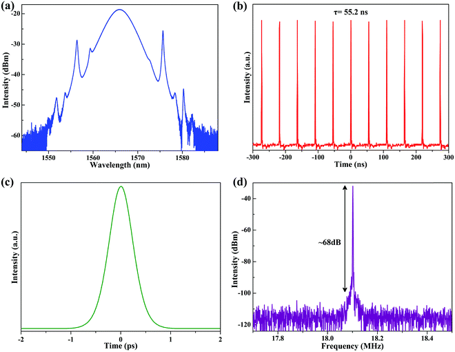 | ||
| Fig. 7 Typical characteristics of mode-locking EDFL. (a) Emission spectrum. (b) Output pulse train; (c) single pulse profile; (d) RF spectrum. | ||
In order to reveal the long-term stability of the mode-locking EDFL, we measured the output spectrum at 6 h intervals over 1 day under the same experimental conditions, as shown in Fig. 8(a). Both the central wavelength and the 3 dB bandwidth stay almost the same, indicating the excellent repeatability and long-term stability of the mode-locking EDFL. Fig. 8(b) shows the output power of the mode-locking EDFL as a function of the pump power. By increasing the pump power from 66 to 200 mW, the output power increases almost linearly from 0.2 to 7.9 mW, resulting in a slope efficiency of 5.7%. When the pump power is beyond 200 mW, the pulse train becomes unstable, and pulse splitting can be observed. Thus, the maximum pulsed energy of this stable mode-locking EDFL is about 0.44 nJ. In order to estimate the optical damage threshold of the CNCs-450/PVA SA, we increased the pump power to 500 mW (the maximum output power of the pump source that we used) and left it for 3 hours. Then, by decreasing the pump power from 500 to 0 mW, we found that the stable mode-locking EDFL can be obtained again in the range of 66 to 200 mW. Thus, the optical damage threshold of the CNCs-450/PVA SA is over 500 mW.
 | ||
| Fig. 8 (a) Output spectrum measured every 6 h showing long-term stability of mode-locking EDFL. (b) Output power as a function of pump power. | ||
A detailed comparison of CNCs with other low-dimensional material-based SAs is summarized in Table 1. It clearly demonstrates that the as-synthesized CNCs have outstanding performance as a competitive photonic device for realizing pulsed laser generation. The carbon nanocage SA has the advantages of (1) being cost-effective, as the fabrication temperature is relatively low; (2) controllable nonlinear optical properties, as the modulation depth and saturation intensity can be controlled with different carbonization temperatures; (3) long-term stability and relatively high optical damage threshold, as both the Q-switching EDFL based on CNCs-350/PVA or CNCs-400/PVA and mode-locking based on CNCs-450/PVA SA have long-term operation stability (can operate stably more than several weeks) with relatively high optical damage threshold (more than 500 mW).
| SA type | Laser type | Wavelength (nm) | Pulse duration | SNR (dB) | Slope efficiency (%) | Ref. |
|---|---|---|---|---|---|---|
| Carbon nanotubes | Mode-locking | 1518–1558 | 706 fs | 70 | // | 20 |
| Graphene | Mode-locking | 1565 | 756 fs | 65 | 3 | 14 |
| Graphene oxide | Mode-locking | 1559.56 | 582 fs | 56 | 2.6 | 62 |
| Graphdiyne | Mode-locking | 1564.7 | 734 fs | 41.77 | 1 | 25 |
| CuS | Mode-locking | 1558 | 1.57 ps | 70 | // | 57 |
| Gu1.8S | Q-switching | 1567.2 | 2 μs | // | 1 | 63 |
| Gold nanostars | Q-switching | 1564.5 | 5.3 μs | // | 1.9 | 64 |
| MoSe2 | Q-switching | 1566 | 4.8 μs | // | // | 65 |
| CNCs-350 | Q-switching | 1568.6 | 2.9 μs | // | 4.9 | Our work |
| CNCs-400 | Q-switching | 1569.3 | 3.3 μs | // | 5 | Our work |
| CNCs-450 | Mode-locking | 1565.9 | 638 fs | 68 | 5.7 | Our work |
4. Conclusions
CNCs were fabricated by carbonizing EDA precursor inside a zeolite ZnAlPO-12 template at a temperature of 350, 400, and 450 °C, respectively. The nonlinear optical property of the CNCs/PVA composite was investigated, and the application of CNCs/PVA as a new SA for pulsed fiber laser generation was fulfilled. Depending on the fabrication temperature, the modulation depth and saturation intensity of CNCs-350/PVA are 45% and 2.2 MW cm−2, respectively. By inserting this SA into the fiber laser cavity, a stable Q-switching operation centered at 1568.6 nm with pulse duration of 2.9 μs can be achieved. In addition, the stable Q-switching that centered at 1569.3 nm with pulse duration of 3.3 μs can also be obtained by using the CNCs-400/PVA SA. As for the CNCs-450/PVA SA, the modulation depth and saturation intensity are 35.2% and 2 MW cm−2, respectively. By inserting this SA into the fiber laser cavity, the stable mode-locking operation centered at 1565.9 nm with pulse duration of 638 fs can be achieved. Our results clearly demonstrate that CNCs exhibit excellent performance as a competitive SA for pulsed laser generation. We believe that CNCs could have great potential application in nonlinear optics and photonic devices.Author contributions
Xintong Xu and Shuangchen Ruan conceived the idea and supervised the research. Jiaqi Chen and Xintong Xu performed the experiment and wrote the manuscript. Shaowen Chu and Lang Sun performed characterization of the materials. Dalin Sun and Juan Lu tested the optical characteristics of the materials. Xintong Xu and Dingdi Wan analyzed the data. All authors contributed to revising the paper.Conflicts of interest
There are no conflicts to declare.Acknowledgements
This work was supported by the National Natural Science Foundation of China (No. 61705134), the Science and Technology Innovation Commission of Shenzhen (No. JCYJ20180305124706833), and the Special Project of Self-made Experimental Instruments and Equipment of Shenzhen Technology University (No. 20214027010014).References
- B. Oktem, C. Ülgüdür and F. Ilday, Nat. Photonics, 2010, 4, 307–311 CrossRef CAS.
- P. Grelu and N. Akhmediev, Nat. Photonics, 2012, 6, 84–92 CrossRef CAS.
- M. Fermann and I. Hartl, Nat. Photonics, 2013, 7, 868–874 CrossRef CAS.
- U. Keller, Nature, 2003, 424, 831–838 CrossRef CAS.
- W. Fu, L. G. Wright, P. Sidorenko, S. Backus and F. W. Wise, Opt. Express, 2018, 26, 9432–9463 CrossRef CAS PubMed.
- Y. Zuo, W. Yu, C. Liu, X. Cheng, R. Qiao, J. Liang, X. Zhou, J. Wang, M. Wu, Y. Zhao, P. Gao, S. Wu, Z. Sun, K. Liu, X. Bai and Z. Liu, Nat. Nanotechnol., 2020, 15, 987–991 CrossRef CAS.
- T. Jiang, K. Yin, C. Wang, J. You, H. Ouyang, R. Miao, C. Zhang, K. Wei, H. Li, H. Chen, R. Zhang, X. Zheng, Z. Xu, X. Cheng and H. Zhang, Photonics Res., 2020, 8, 78–90 CrossRef CAS.
- G. Wang, A. A. Baker-Murray and W. J. Blau, Laser Photonics Rev., 2019, 13, 1800282 CrossRef.
- W. Liu, M. Liu, X. Liu, X. Wang, H. Deng, M. Lei, Z. Wei and Z. Wei, Adv. Opt. Mater., 2020, 8, 1901631 CrossRef CAS.
- J. Yang, J. Hu, H. Luo, J. Li, J. Liu, X. Li and Y. Liu, Photonics Res., 2020, 8, 70–77 CrossRef CAS.
- U. Keller, K. J. Weingarten, F. X. Kartner, D. Kopf, B. Braun, I. D. Jung, R. Fluck, C. Honninger, N. Matuschek and J. Aus der Au, IEEE J. Sel. Top. Quantum Electron., 1996, 2, 435–453 CrossRef CAS.
- Z. C. Luo, A. P. Luo and W. C. Xu, IEEE Photonics J., 2011, 3, 64–70 Search PubMed.
- Y. Mashiko, E. Fujita and M. Tokurakawa, Opt. Express, 2016, 24, 26515–26520 CrossRef CAS PubMed.
- Q. Bao, H. Zhang, Y. Wang, Z. Ni, Y. Yan and Z. X. Shen, Adv. Funct. Mater., 2009, 19, 3077–3083 CrossRef CAS.
- D. Popa, Z. Sun, F. Torrisi, T. Hasan, F. Wang and A. C. Ferrari, Appl. Phys. Lett., 2010, 97, 203106 CrossRef.
- Z. Sun, T. Hasan, F. Torrisi, D. Popa, G. Privitera and F. Wang, ACS Nano, 2010, 4, 803–810 CrossRef CAS PubMed.
- F. Bonaccorso, Z. Sun, T. Hasan and A. C. Ferrari, Nat. Photonics, 2010, 4, 611–622 CrossRef CAS.
- N. Li, J. Huang, B. Xu, Y. Cai, J. Lu and L. Zhan, Photonics Res., 2019, 7, 1209–1213 CrossRef CAS.
- Y. Lin, C. Yang, J. Liou, C. Yu and G. Lin, Opt. Express, 2013, 21, 16763–16776 CrossRef PubMed.
- F. Wang, A. G. Rozhin, V. Scardaci, Z. Sun, F. Hennrich and I. H. White, Nat. Nanotechnol., 2008, 3, 738–742 CrossRef CAS.
- L. Huang, Y. Zhang and X. Liu, Nanophotonics, 2020, 9, 2731–2761 CrossRef CAS.
- Y. Cui and X. Liu, Photonics Res., 2019, 7, 423–430 CrossRef CAS.
- L. Hou, H. Guo, Y. Wang, J. Sun, Q. Lin and Y. Bai, Opt. Express, 2018, 26, 9063–9070 CrossRef CAS PubMed.
- X. Liu, D. Popa and N. Akhmediev, Phys. Rev. Lett., 2019, 123, 093901 CrossRef CAS PubMed.
- Y. Zhao, P. Guo, X. Li and Z. Jin, Carbon, 2019, 149, 336–341 CrossRef CAS.
- W. Liu, L. Pang, H. Han, K. Bi, M. Lei and Z. Wei, Nanoscale, 2017, 9, 5806–5811 RSC.
- W. Liu, L. Pang, H. Han, M. Liu, M. Lei and S. Fang, Opt. Express, 2017, 25, 2950–2959 CrossRef CAS.
- R. Lü, Y. Wang, J. Wang, W. Ren, L. Li and S. Liu, Photonics Res., 2019, 7, 431–436 CrossRef.
- Z. C. Luo, M. Liu, H. Liu, X. W. Zheng, A. P. Luo and C. J. Zhao, Opt. Lett., 2013, 38, 5212–5215 CrossRef PubMed.
- Z. Dou, Y. Song, J. Tian, J. Liu, Z. Yu and X. Fang, Opt. Express, 2014, 22, 24055–24061 CrossRef CAS.
- M. Jung, J. Lee, J. Koo, J. Park, Y. W. Song and K. Lee, Opt. Express, 2014, 22, 7865–7874 CrossRef CAS.
- H. Liu, X. W. Zheng, M. Liu, N. Zhao, A. P. Luo and Z. C. Luo, Opt. Express, 2014, 22, 6868–6873 CrossRef CAS.
- K. Yin, B. Zhang, L. Li, T. Jiang, X. Zhou and J. Hou, Photonics Res., 2015, 3, 72–76 CrossRef CAS.
- Y. Lin, S. Lin, Y. Chi, C. Wu, C. Cheng, W. Tseng, J. He, C. Wu, C. Lee and G. Lin, ACS Photonics, 2015, 2, 481–490 CrossRef CAS.
- Y. Lin, C. Yang, S. Lin, W. Tseng, Q. Bao, C. Wu and G. Lin, Laser Phys. Lett., 2014, 11, 055107 CrossRef CAS.
- M. Zhang, Q. Wu, F. Zhang, L. Chen, X. Jin and Y. Hu, Adv. Opt. Mater., 2019, 7, 1800224 CrossRef.
- X. Jin, G. Hu, M. Zhang, Y. Hu, T. Albrow-Owen, R. C. T. Howe, T. C. Wu, Q. Wu, Z. Zheng and T. Hasan, Opt. Express, 2018, 26, 12506–12513 CrossRef CAS PubMed.
- H. Chen, F. Wang, M. Qian, X. Zhou, Z. Li, T. Cheng and G. Qin, J. Mater. Chem. C, 2020, 8, 4919–4925 RSC.
- X. Li, J. Feng, W. Mao, F. Yin and J. Jiang, J. Mater. Chem. C, 2020, 8, 14386–14392 RSC.
- Y. Feng, L. Du, Y. He, Q. Yi, J. Li, Q. Duan, S. Chen, L. Miao and C. Zhao, J. Mater. Chem. C, 2021, 9, 6445–6451 RSC.
- J. He, L. Tao, H. Zhang, B. Zhou and J. Li, Nanoscale, 2019, 11, 2577–2593 RSC.
- L. Li, L. Pang, Q. Zhao, W. Liu and Y. Su, J. Mater. Chem. C, 2020, 8, 1104–1109 RSC.
- L. Li, L. Pang, Q. Zhao, Y. Wang and W. Liu, Nanoscale, 2020, 12, 4537–4543 RSC.
- L. Li, L. Pang, Y. Wang and W. Liu, Nanoscale, 2021, 13, 2511–2518 RSC.
- Q. Wu, L. Yang, X. Wang and Z. Hu, Adv. Mater., 2020, 32, 1904177 CAS.
- X. Song, Y. Jiang, F. Cheng, J. Earnshaw, J. Na, X. Li and Y. Yamauchi, Small, 2021, 17, 2004142 CrossRef CAS.
- Q. Wu, L. Yang, X. Wang and Z. Hu, Acc. Chem. Res., 2017, 50, 435–444 CrossRef CAS.
- B. Cao, Q. Zhang, H. Liu, B. Xu, S. Zhang, T. Zhou, J. Mao, W. K. Pang, Z. Guo, A. Li, J. Zhou, X. Chen and H. Song, Adv. Energy Mater., 2018, 8, 1801149 CrossRef.
- Q. Hu, G. Li, G. Li, X. Liu, B. Zhu, X. Chai, Q. Zhang, J. Liu and C. He, Adv. Energy Mater., 2019, 9, 1803867 CrossRef.
- J. Zhao, H. Lai, Z. Lyu, Y. Jiang, K. Xie, X. Wang, Q. Wu, L. Yang, Z. Jin, Y. Ma, J. Liu and Z. Hu, Adv. Mater., 2015, 27, 3541–3545 CrossRef CAS PubMed.
- Y. Bu, T. Sun, Y. Cai, L. Du, O. Zhuo, L. Yang, Q. Wu, X. Wang and Z. Hu, Adv. Mater., 2017, 29, 1700470 CrossRef.
- Y. Jiang, L. Yang, T. Sun, J. Zhao, Z. Lyu, O. Zhuo, X. Wang, Q. Wu, J. Ma and Z. Hu, ACS Catal., 2015, 5, 6707–6712 CrossRef CAS.
- L. Y. Du, Q. Wu, L. J. Yang, X. Wang, R. C. Che, Z. Y. Lyu, W. Chen, X. Z. Wang and Z. Hu, Nano Energy, 2019, 57, 34–40 CrossRef CAS.
- L. Y. Du, X. Y. Cheng, F. J. Gao, Y. B. Li, Y. F. Bu, Z. Q. Zhang, Q. Wu, L. J. Yang, X. Z. Wang and Z. Hu, Chem. Commun., 2019, 55, 6365–6368 RSC.
- J. B. Parise, Inorg. Chem., 1985, 24, 4312–4316 CrossRef CAS.
- H. Lu, J. Xu, P. Gao, W. Yan, F. Deng and R. Xu, Microporous Mesoporous Mater., 2015, 208, 105–112 CrossRef CAS.
- X. Zhang, S. Liu, D. Tan, Y. Xian, D. Zhang, Z. Zhang, Y. Liu, X. Liu and J. Qiu, Chem. Mater., 2020, 32, 3180–3187 CrossRef CAS.
- E. Garmire, IEEE J. Sel. Top. Quantum Electron., 2000, 6, 1094–1110 CAS.
- E. J. Lee, S. Y. Choi, H. Jeong, N. H. Park, W. Yim, M. H. Kim, J. K. Park, S. Son, S. Bae, S. J. Kim, K. Lee, Y. H. Ahn, K. J. Ahn, B. H. Hong, J. Y. Park, F. Rotermund and D. I. Yeom, Nat. Commun., 2015, 6, 6851 CrossRef CAS.
- Y. Chen, G. Jiang, S. Chen, Z. Guo, X. Yu, C. Zhao, H. Zhang, Q. Bao, S. Wen, D. Tang and D. Fan, Opt. Express, 2015, 23, 12823–12833 CrossRef CAS.
- X. Xu, S. Ruan, J. Zhai, L. Li, J. Pei and Z. Tang, Photonics Res., 2018, 6, 996–1002 CrossRef CAS.
- Z. Chen, H. Wang, Y. Wang, R. Lv, X. Yang and J. Wang, Carbon, 2019, 144, 737–744 CrossRef CAS.
- M. Liu, D. Zhou, Z. Jia, Z. Li, N. Li, S. Li, Z. Kang, J. Yi, C. Zhao, G. Qin, H. Song and W. Qin, J. Mater. Chem. C, 2017, 5, 4034–4039 RSC.
- Z. Kang, M. Liu, Z. Li, S. Li, Z. Jia, C. Liu, W. Qin and G. Qin, Photonics Res., 2018, 6, 549–553 CrossRef CAS.
- R. I. Woodward, R. C. T. Howe, T. H. Runcorn, G. Hu, F. Torrisi, E. J. R. Kelleher and T. Hasan, Opt. Express, 2015, 23, 20051–20061 CrossRef CAS.
| This journal is © The Royal Society of Chemistry 2022 |

