
 Open Access Article
 This Open Access Article is licensed under a
 Creative Commons Attribution 3.0 Unported Licence
Droplets on substrates with oscillating wettability†
Josua
Grawitter
 * and
Holger
Stark
*
* and
Holger
Stark
*
Technische Universität Berlin, Institut für Theoretische Physik, Straße des 17. Juni 135, 10623 Berlin, Germany. E-mail: josua.grawitter@physik.tu-berlin.de; holger.stark@tu-berlin.de
First published on 27th September 2021
Abstract
In recent decades novel solid substrates have been designed which change their wettability in response to light or an electrostatic field. Here, we investigate a droplet on substrates with oscillating uniform wettability by varying minimum and maximum contact angles and frequency. To simulate this situation, we use our previous work [Grawitter and Stark, Soft Matter, 2021, 17, 2454], where we implemented the boundary element method in combination with the Cox–Voinov law for the contact-line velocity, to determine the fluid flow inside a droplet. After a transient regime the droplet performs steady oscillations, the amplitude of which decreases with increasing frequency. For slow oscillations our numerical results agree well with the linearized spherical-cap model. They collapse on a master curve when we rescale frequency by a characteristic relaxation time. In contrast, for fast oscillations we observe significant deviations from the master curve. The decay of the susceptibility is weaker and the phase shift between oscillations in wettability and contact angle stays below the predicted π/2. The reason becomes obvious when studying the combined dynamics of droplet height and contact angle. It reveals non-reciprocal shape changes during one oscillation period even at low frequencies due to the induced fluid flow inside the droplet, which are not captured by the spherical-cap model. Similar periodic non-reciprocal shape changes occur at low frequencies when the droplet is placed on an oscillating nonuniform wettability profile with six-fold symmetry. Such profiles are inspired by the light intensity pattern of Laguerre–Gauss laser modes. Since the non-reciprocal shape changes induce fluid circulation, which is controllable from the outside, our findings envisage the design of targeted microfluidic transport of solutes inside the droplet.
1 Introduction
The shape a liquid droplet forms on a flat surface is determined by the wettability landscape of the surface. On more wettable parts of the surface, the droplet spreads out and on less wettable parts it contracts.1 In the past two decades researchers have developed substrates the wettability of which can be controlled such that patterns that change in space and/or time can be created.2–4 For example, the wetted substrates become switchable due to a single layer of light-responsive molecules,2,5,6 electro-responsive molecules,7 an array of light-responsive pillars,8–10 or more complex nanostructures.11,12 Regardless of the specific mechanism, controlling the dynamics of a liquid drop by time-varying wettability patterns is not yet fully explored, despite its importance for lab-on-a-chip devices13 and for targeted deposition of solutes, for example, in printing devices.14So far, much research has aimed at understanding wetting on substrates with static non-uniform wettability patterns. Early theoretical studies used perturbation methods to analytically estimate the influence of small local wettability gradients on droplets with simple circular or cylindrical shapes.15,16 Later, experimental and numerical work investigated more complex shapes which occur, for example, when a droplet crosses a static step in wettability,17,18 flows over two neighboring stripes of increased wettability,19 over a checker-board pattern,20,21 or random spatial fluctuations in wettability.21 From the perspective of the droplet these patterns also become time-varying if the droplets starts to move, for example, on an inclined substrate.22 Furthermore, a droplet may trigger a chemical reaction with the substrate and thereby create a wettability gradient, which moves it forward.23 Taking into account the switchable substrates introduced above, we have shown recently how a chemically inert droplet responds to moving steps in wettability.24 Thus, the droplet's motion is under external control.
In this article we present a theoretical investigation how a small liquid droplet behaves on a substrate with oscillations in uniform wettability. We also give a brief outlook toward its behavior on a substrate with oscillations of a non-uniform wettability pattern. Generally, small sessile droplets form spherical caps on flat substrates with uniform wettability because that shape minimizes its total surface energy on a flat substrate.25 However, when the substrate's wettability oscillates, the droplet continually tries to follow but cannot relax to its equilibrium shape. Its continuous motion in turn gives rise to internal flow in the droplet. We are interested in both—the droplet shape during oscillation and the accompanying internal flow. Since at small length scales viscous forces dominate inertia within the droplet, the internal fluid flow is described by the Stokes equations.26 We solve these using the boundary element method, the implementation of which we have described in a previous work.24 At the edge of the droplet-substrate interface (the contact line), we use the Cox–Voinov law to calculate the velocity of the contact line.27 We have previously validated and applied our method to droplets that are steered by moving steps in wettability.24
The case of droplets exposed to oscillating wettability is distinct from droplets on vertically vibrated substrates, which have been studied in ref. 28–30. For the droplet such vibrations only play a role in the presence of inertia or external forces. They affect the droplet as a whole, while oscillations in wettability only act via forces at the contact line. Vertical vibrations have been shown to give rise to ripples that travel up the side of the droplet and to generate higher-harmonic deformations of the contact line for water28,29 as well as for mercury droplets.30 At large amplitudes of the vibrations the droplet breaks up by ejecting small amounts of liquid at its top.29 As we study wettability oscillations in the absence of inertia, we will not observe such extreme phenomena in our case.
Our theoretical approach stands alongside two other continuum approaches to dynamic wetting. In the first approach, one uses a thin-film equation to evaluate the droplet dynamics via its height profile,31–34 which means the contact angle should be small and cannot exceed 90 degrees. Another approach, which we will discuss in detail below, is the spherical cap model. It constraints the shape of the droplet to a spherical cap27,35 and does not capture fluid flow within the droplet. The spherical cap shape is motivated by the equilibrium shape of a droplet on a substrate with uniform wettability. With our approach, we are able to evaluate the applicability of the spherical cap model and investigate the internal flow field of the droplet.
Our findings add to the microfluidics toolbox36–38 another way to interact with and manipulate droplets by placing them on substrates with oscillating wettability. Specifically, we find that the contact angle oscillations of the droplet decrease with increasing frequency. For slow oscillations this can be well described by the spherical-cap model, which even provides a characteristic time scale to map the oscillations onto a common master curve. However, the master curve is no longer applicable for fast oscillations. A more detailed study of the droplet dynamics in terms of two shape variables, such as contact angle and droplet height, reveals that they oscillate out-of-phase with each other. Thus, the droplet performs a non-reciprocal motion during one oscillation period, which cannot be described by the spherical-cap model. It is due to fluid flow within the droplet, which gives rise to fluid circulation within the droplet.
Our article is structured as follows: in Section 2 we reiterate the theoretical basis of our boundary element method applied to dynamic wetting. In Section 3 we describe and discuss our findings in detail. First, in Section 3.1 we present the basic phenomenology of the droplet oscillations. We analyze them using linear-response theory and the spherical-cap model, where the contact angle serves as a single shape characteristic. Second, in Section 3.2 we look at the coupled dynamics of contact angle and height, reveal the non-reciprocal motion of the droplet, and discuss its implications for the internal fluid flow. Third, in Section 3.3 we study a closely-related example of a droplet on a substrate with an oscillating non-uniform wettability pattern. Finally, we conclude in Section 4.
2 Simulation method
The motion of a droplet consisting of an incompressible simple liquid is completely described by the dynamics of its interfaces: the gas–liquid and the solid–liquid interface. The motion of any point s on the interfaces is governed by the fluid velocity field at this point:| ṡ = v(s). | (1) |
2.1 Stokes flow
We consider droplets in which viscous drag dominates inertia, which is the limit of Stokes or creeping flow.39The equations govering the velocity field v of Stokes flow are
| μ∇2v = ∇p, ∇·v = 0, | (2) |
 | (3) |
 | (4) |
2.2 Boundary conditions
On the liquid–gas interface the normal stress balances surface tension forces due to mean curvature κ of the interface, i.e., σn = γκn, where γ is the surface tension of the liquid–gas interface.On the solid liquid interface (at the substrate) two conditions apply: firstly, the interface cannot deform along its normal ez and therefore vz = 0. Secondly, roughness of the substrate introduces a small amount of slip with slip length λ, which we account for by setting λσn = μv tangential to the interface.41
As a boundary condition on the contact line, we choose its velocity along the substrate according to the Cox–Voinov law27,42
 | (5) |
The boundary conditions introduce several material parameters in addition to viscosity μ. For our simulations we choose dimensionless parameters. They correspond, for example, to a droplet with an initial radius R0 = 100 μm of its circular base area and made of a 90% glycerol and 10% water mixture. This reference system was studied in experiments by de Ruijter et al.35 The mixture has μ = 209 mPa s, kinematic viscosity ν = μ/ρ = 169 mm2 s−1, γ = 65.3 mN m−1, λ = 1 nm, and ln(h/λ) = 44. The latter value was observed by de Ruijter et al. by fitting the spherical cap model with eqn (11) and (12) mentioned below to their experimental data. Furthermore, we choose the initial contact angle θdyn to be the time average of θeq. We calculate and report our data in units of R0 for length, τ = R02/ν for time, and F0 = νμ for force. Thus the remaining dimensionless parameters are ![[small gamma, Greek, tilde]](https://www.rsc.org/images/entities/i_char_e0dd.gif) = γR0/F0 = 0.19 and
= γR0/F0 = 0.19 and ![[small lambda, Greek, tilde]](https://www.rsc.org/images/entities/i_char_e0df.gif) = λ/R0 = 10−5.
= λ/R0 = 10−5.
Based on these parameters and eqn (5), we estimate the ratio between inertial and viscous forces, i.e., the Reynolds number Re. It contains a characteristic flow velocity, for which we take the velocity of the contact line. According to eqn (5) the prefactor provides a relevant velocity scale so that we obtain
 | (6) |
2.3 Boundary element method
To solve for the velocity field at the droplet's interfaces, we construct a triangular mesh and discretize the integral equation. We then integrate the dynamic of the mesh in time using an adaptive 5th order Runge–Kutta method.46 The full details of our boundary element method are provided in ref. 24. Briefly, to discretize eqn (3) we divide the droplet surface into polygonal regions, each with a vertex at its center. The polygons are then decomposed into triangles and we integrate separately over each triangle using Gaussian quadrature47 with 400 sampling points for singular integrands and 9 sampling points for nonsingular integrands. Once we have solved the discretized equation and the surface velocity field is known, we can use the boundary integral eqn (3) to evaluate the flow field in the interior of the droplet. Similar numerical approaches have been used to study dewetting of polymer microdroplets48,49 and for bubbles on a solid surface under the influence of an acoustic field.503 Droplet on a substrate of oscillating uniform wettability
We consider a droplet on a substrate, where the uniform wettability expressed by the equilibrium contact angle θeq(t) oscillates with a frequency f between a minimum (θmineq) and maximum (θmaxeq) value:| θeq(t) = θmineq + (θmaxeq − θmineq)·sin2(πft) | (7) |
We now discuss how the droplet reacts on oscillations in the wettability and compare our numerical results to the outcome from the spherical-cap model. Then, we show that the induced flow in the droplet is non-reciprocal so that it effectively pumps fluid during one oscillation cycle.
3.1 Phenomenology
After an initial transient behavior, the droplet settles into a periodic deformation which oscillates with the same frequency as the wettability. For three frequencies separated by a factor of 10, we display the dynamic contact angle in Fig. 1. We observe that the range covered by the dynamic contact angle decreases with increasing frequency. For slow oscillations the contact angle nearly follows the prescribed equilibrium value of the substrate wettability, while for fast oscillations it barely varies leading to an almost steady droplet shape. Note that in our example the droplet does not oscillate about the mean value of θmaxeq = 120° and θmineq = 60°. Furthermore, we observe a phase shift between the oscillating equilibrium and dynamic contact angles, which also depends on f. Note, for different combinations of θmaxeq and θmineq we provide Videos M01–M03 in the ESI,† where a relatively small frequency of f = 10−3τ−1 is used (for details see footnote, ESI†).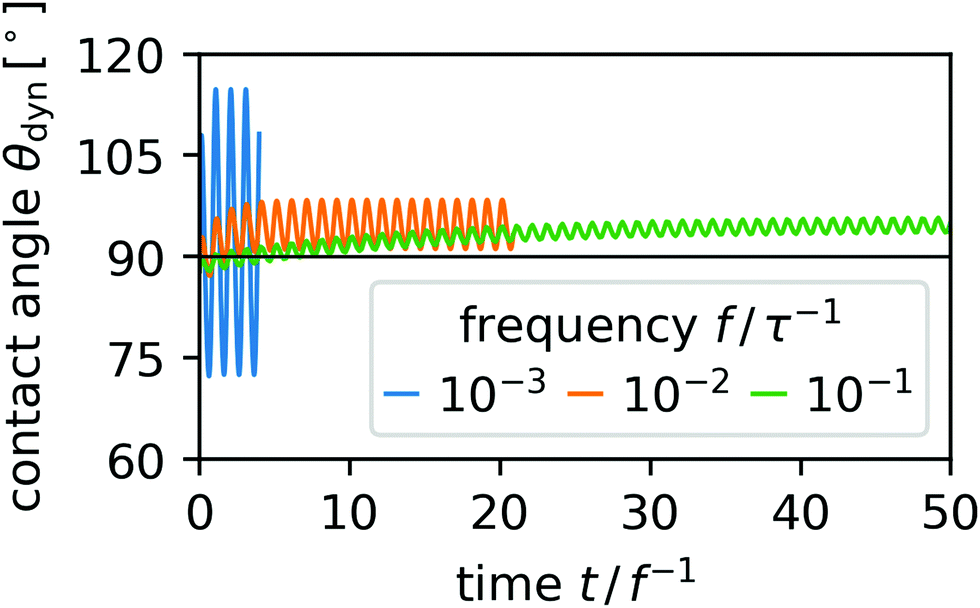 | ||
| Fig. 1 Contact angle oscillations in response to oscillations in wettability for three frequencies f with θmaxeq = 120° and θmineq = 60°. | ||
To quantify the response of the droplet to the oscillating substrate wettability, we introduce the nonlinear susceptibility χ = |χ|![[thin space (1/6-em)]](https://www.rsc.org/images/entities/char_2009.gif) exp(iΔφ) with absolute value |χ| and phase shift Δφ. The imaginary unit is indicated by i. We extract |χ| from
exp(iΔφ) with absolute value |χ| and phase shift Δφ. The imaginary unit is indicated by i. We extract |χ| from
 | (8) |
 | (9) |
| Δφ(f) = arg[αdyn(f)] − arg[αeq(f)], | (10) |
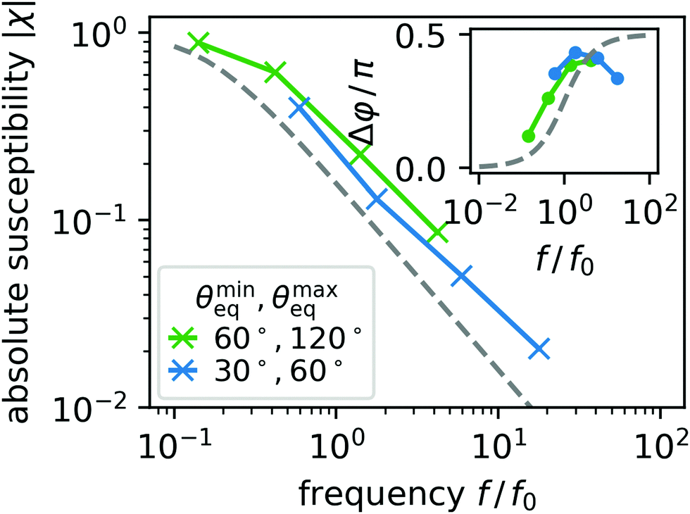
In Fig. 2 we plot the absolute value |χ| over frequency for different combinations of θmaxeq and θmineq. All three curves show the expected decrease of |χ| with increasing f. Furthermore, for larger difference θmaxeq − θmineq and larger values of the equilibrium contact angles, the curves are shifted to larger frequencies but roughly have the same shape. This suggests by rescaling frequency appropriately, they fall on a master curve. The inset of Fig. 2 plots the corresponding phase shift. For small frequencies of the oscillating wettability the phase shift tends towards zero for the green curve meaning that the dynamic contact angle follows the prescribed wetting angle instantaneously.
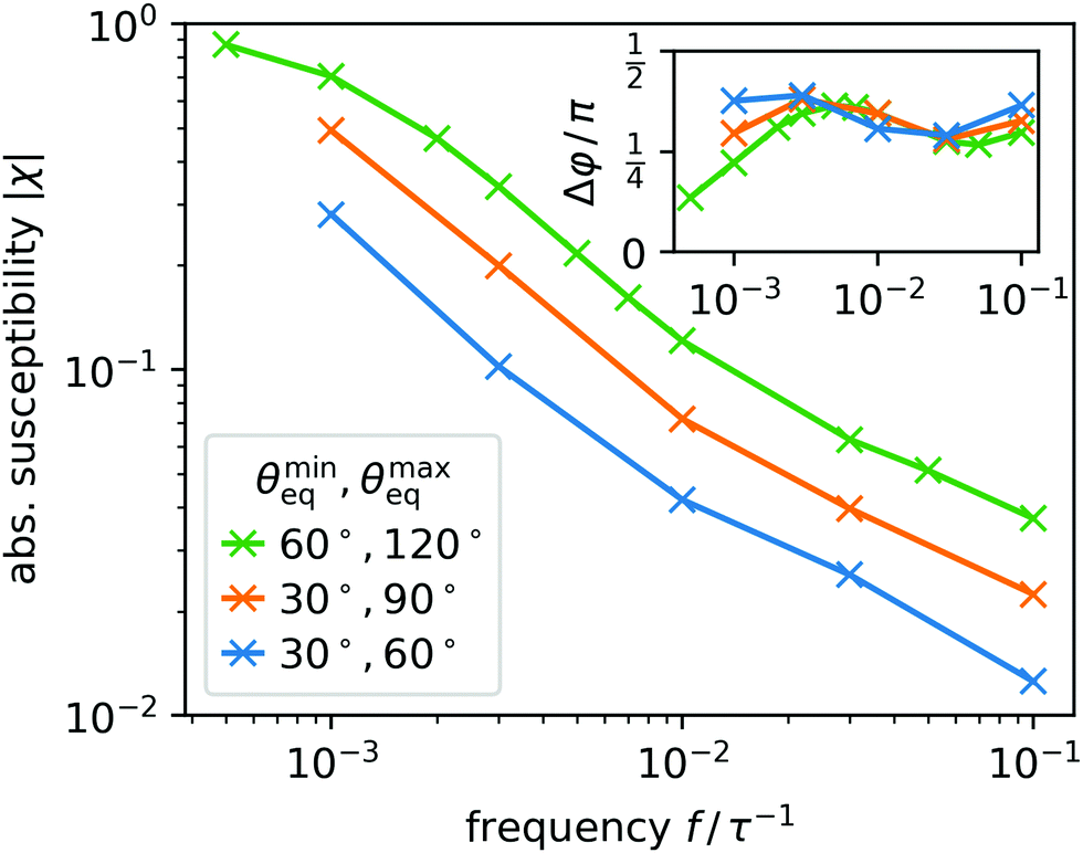 | ||
| Fig. 2 Absolute susceptibility |χ| as a function of oscillation frequency f = ω/2π in units of τ−1 for three combinations of θmaxeq and θmineq. The inset shows the corresponding phase shift Δφ. | ||
To gain more insights and also pursue the idea of the master curve further, we compare our observations to the spherical-cap model,35 where the droplet always keeps the shape of a spherical cap and the dynamics is solely governed by the Cox–Voinov law for the contact line. This will allow us to distinguish phenomena inherent in the contact-line friction from phenomena which are due to the freely deformable liquid-gas interface and the initiated fluid flow in the droplet as determined in our boundary element method. For slow temporal variations in the wettability we expect the spherical-cap model to be valid since fluid flow in the droplet is weak, while for larger frequencies deviations should occur. We now go into more detail.
In the spherical-cap model the shape of the droplet is constrained to a single degree of freedom for which it determines a dynamic equation.35 Here, we follow ref. 35 and express the model in terms of the dynamic contact angle θdyn,
 | (11) |
 | (12) |
 | (13) |
![[small theta, Greek, macron]](https://www.rsc.org/images/entities/i_char_e0c9.gif) eq = (θmaxeq − θmineq)/2 and obtain
eq = (θmaxeq − θmineq)/2 and obtain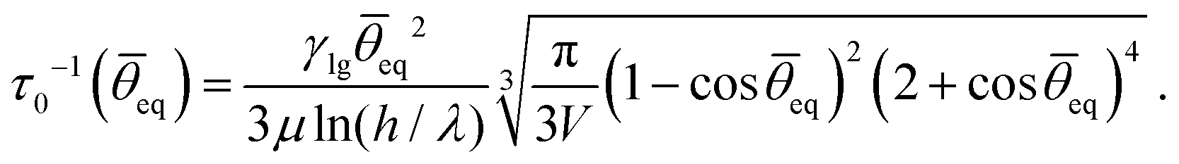 | (14) |
eq towards eq. Now, we approximate eqn (13) by using the constant τ0 instead of the exact derivative of g. Rescaling time by τ0, we finally arrive at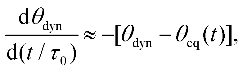 | (15) |
Using time rescaled with τ0 also in the full spherical-cap model, we can rewrite eqn (11) and (12) in a non-dimensionalized form as
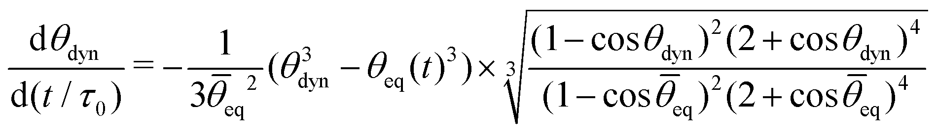 | (16) |
eq.
We now explore the linerarized model. By taking the Fourier transform of eqn (15), one finds the dynamical susceptibility χ(ω), which quantifies how θdyn responds to an oscillation in θeq: ![[small straight theta, Greek, circumflex]](https://www.rsc.org/images/entities/i_char_e12d.gif) dyn(ω) = χ(ω)eq(ω) with
dyn(ω) = χ(ω)eq(ω) with
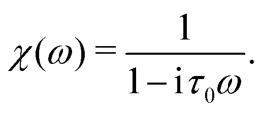 | (17) |
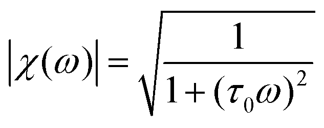 | (18) |
| φ(ω) = arctan(τ0ω). | (19) |
Because eqn (18) and (19) do not depend on any material parameters besides the characteristic relaxation time τ0, they are candidates for the master curves for our simulation results in Fig. 2. We simply need to rescale frequency by τ0−1 calculated for the specific values of θmineq and θmaxeq. In Fig. 3(a) and (b) we display the master curves as dashed lines together with the results from our boundary element method (BEM) using rescaled frequencies. First, in Fig. 3(a) we observe that the BEM results all fall on a common master curve for f < τ0−1, which perfectly matches the linear model in this range. For f > τ0−1 the BEM results do not follow a common master curve and they deviate from the linear model. We observe that the absolute susceptibility enters an algebraic decay with an approximate exponent −0.5 rather than −1 as predicted by the linear model. Second, in Fig. 3(b) we similarly observe that the BEM results approach the linear model for small f, however they start to deviate significantly for fτ0 > 3 × 10⁻¹. The phase shift varies between roughly 0.3π and 0.4π rather than approaching 0.5π as predicted analytically by the linear model in eqn (19) and indicated as dashed line. The phase shifts beyond fτ0 > 3 × 10⁻¹ apparently depend on θmaxeq and θmineq.
 | ||
| Fig. 3 Absolute susceptibility |χ| (a) and phase shift Δφ (b) as a function of oscillation frequency f = ω/2π in units of f0 = τ0−1 determined in the simulations for three combinations of θmaxeq and θmineq (coloured crosses with solid lines to guide the eye, see legend). The dashed grey lines indicate the prediction of the linear model in eqn (18) and (19), respectively. The dotted black line in (a) shows a f−0.5 scaling. | ||
To interpret these observations, we distinguish two regimes: a low frequency regime with fτ0 < 1 and a high frequency regime with fτ0 > 1. In the low frequency regime, the oscillations are sufficiently slow so that the droplet can adapt its shape and keep it close to a spherical cap. Thus, the linear spherical-cap model is valid. In fact, in the limit of vanishing f it becomes exact as the dynamics becomes quasistatic. According to linear response theory, the imaginary part Imχ, which in our linear model from eqn (17) reads
 | (20) |
χ as well as the phase shift Δϕ from eqn (19) are linear in ω at small frequencies, this implies that almost no work performed on the droplet through slow wettability oscillations is dissipated by the friction of the contact line.
In the high frequency regime, the droplet deviates far from the linear model since small |χ| means θdyn barely tracks θeq(t). But also the full spherical cap model is unable to predict the observed behavior for |χ| and Δφ and, in particular, the deviation from a common master curve. This implies that the droplet shape deviates from a spherical cap when fast wettability oscillations are applied. These deviations occur close to the contact line, which can move quickly without displacing much liquid and thereby bends the free surface, i.e., it locally in- or decreases curvature, which is precluded in the spherical cap model. This explains why θdyn is more susceptible at large f, meaning it lies above the prediction of the linear model: a small adjustment of the position of the contact line can drastically alter θdyn and increase in a short time the surface energy of the droplet relative to the equilibrium reference shape for a given θeq. Thus the work performed on the droplet is not completely dissipated. Therefore, the phase shift angle Δφ is below the value π/2, which is expected for a complete dissipation and which is predicted within the spherical-cap model for large frequencies.
The spherical cap model only includes dissipation at the contact line. It does not account for viscous friction, friction at the substrate interface, or the elasticity of the free surface. All of these are present in the BEM results, however. We now want to focus on these contributions by turning our attention toward the internal flow of the droplet and toward its deformation from the spherical cap shape.
3.2 Deformation and pumping
The shape oscillations of the droplet are accompanied by internal fluid flow. When the wettability increases, the droplet wets more area on the substrate and fluid moves from the top of the droplet through its center to the contact line. When the wettability decreases, the droplet wets less area on the substrate and fluid moves in the opposite direction.However, this back-and-forth does not cancel out completely and there is a net displacement of fluid after each period, i.e., fluid is pumped within the droplet, as illustrated in Fig. 4. To quantify the net displacement, we place point-like tracer particles in the droplet and track their motion for one full period of oscillation, so that to each starting point r0 we can assign a displacement
| d(r0) = r(T) − r0, | (21) |
 | ||
| Fig. 4 Displacements d(r) of tracers after one full period in a cross section of a droplet on a substrate with oscillating wettability with θmineq= 60°, θmaxeq = 120°, and f = 10−3τ−1. | ||
To quantify changes in the droplet shape, one can use, e.g., the dynamic contact angle θdyn or the droplet height h. In Fig. 5 we plot two oscillation cycles of θeq(t) in graph (a) together with the corresponding h(t) and its time derivative ḣ(t) in graph (b). We first observe that the height of the droplet adjusts faster to a decrease in wettability than to an increase; meaning, the upward slope of h(t) corresponding to an increase of θeq(t) is larger than the magnitude of the downward slope. We understand this by studying the mobility of the contact line as a function of the dynamic contact angle. When the droplet is equilibrated, i.e., θeq = θdyn and a small change in wettability occurs, i.e. θeq → θeq + δθeq, we calculate the contact line mobility m by linearizing the Cox–Voinov law, eqn (5). The velocity of the contact line becomes
 | (22) |
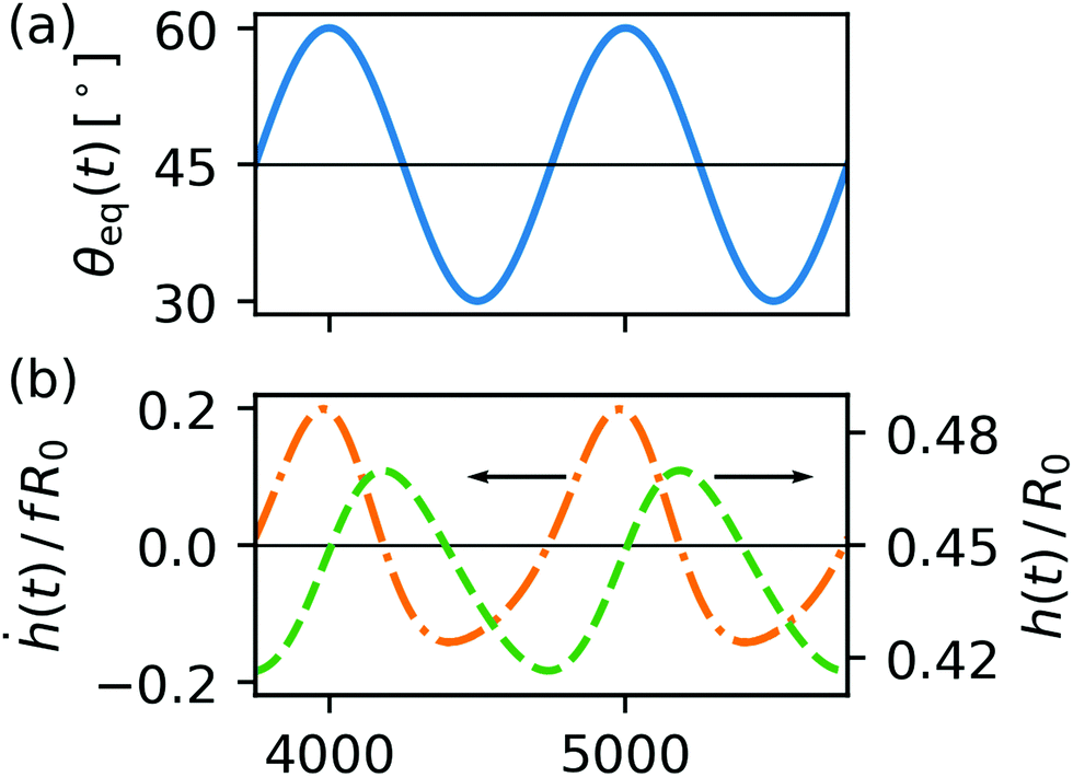 | ||
| Fig. 5 Droplet shape changes for f = 10−3τ−1, θmaxeq = 60° and θmineq = 30°. (a) Wettability of the substrate as a function of time characterized by the equilibrium contact angle θeq. (b) Deformation of the droplet quantified by the height h(t) and rate of deformation quantified by ḣ(t) plotted versus time. Note that ḣ(t) indicates unequal upward and downward slopes for the height dynamics. | ||
However, varying rates of deformation are insufficient to explain a net pumping of the liquid because the equations of Stokes flow, eqn (2), are independent of time. Therefore, a different aspect of the deformation must be responsible for the pumping.
Unlike the spherical cap model our BEM simulations are not constrained to a single degree of freedom. So as a minimal extension for describing the temporal shape variations of the droplet, we investigate the coupled dynamics of two degrees of freedom, contact angle θdyn and droplet height h. In Fig. 6 we represent the droplet dynamics in the configuration space spanned by these two variables; one oscillation of the droplet corresponds to a closed trajectory. Interestingly, the non-zero area enclosed by the trajectory reveals the dynamics of the droplet as non-reciprocal, meaning under time-reversal the dynamics looks different. In our concrete case the droplet assumes slightly different shapes during increasing and decreasing wettability in the course of one period. The non-reciprocal dynamics is clearly due to the flow field generated inside the droplet. Since the spherical-cap model only has one dynamic variable, its dynamics can only be reciprocal. The dashed line in Fig. 6 shows the model prediction for vanishing frequency.‡ Note the non-zero area also means that contact angle and height oscillate out-of-phase with each other. From the study of microswimmers at vanishing Reynolds numbers, we know Purcell's scallop theorem51 which states that non-reciprocal shape changes are needed for microswimmers to move forward. Similarly, the pumping displacement mentioned in the beginning is linked to the non-reciprocal droplet deformation.
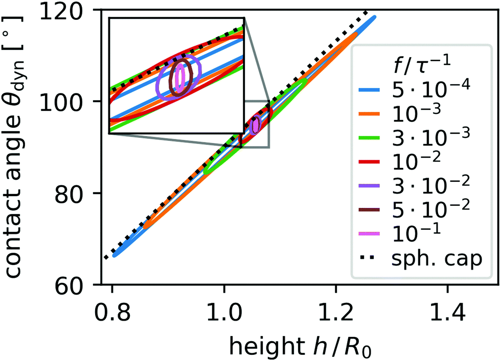 | ||
| Fig. 6 Closed trajectories in configuration space projected onto the h-θdyn plane for various frequencies f (see legend) for θmineq = 60° and θmaxeq = 120°. The limiting behavior of the spherical-cap model with fτ0 ≪ 1 is indicated by the black dashed line. | ||
To quantify the non-reciprocal shape dynamics of the droplet, we take the area enclosed by the trajectory in configuration space, which, in general, is high-dimensional. However, projecting this trajectory into the two-dimensional space spanned by droplet height h and contact angle θdyn, we can immediately calculate the projected area as
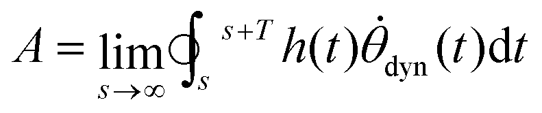 | (23) |
The closed trajectories or loops in the configuration space presented in Fig. 6 extend further in both dimensions and enclose a larger area A as frequency decreases. An increasing area A means the dynamics of the droplet shape becomes less reciprocal. Fig. 7(a) displays the dependence of A on frequency f for all three cases of equilibrium contact angles. We always observe that A decreases for large f, while in the case of θmineq = 60° and θmaxeq = 120° the non-reciprocity A has a maximum and decreases toward small f. The latter is expected since in the quasistationary case of vanishing f the motion has to become reciprocal. Notably, even at small frequencies A is relatively large which means even though the dynamic response approaches that of the spherical cap model, there is still a significant difference between our BEM dynamics and the spherical cap model.
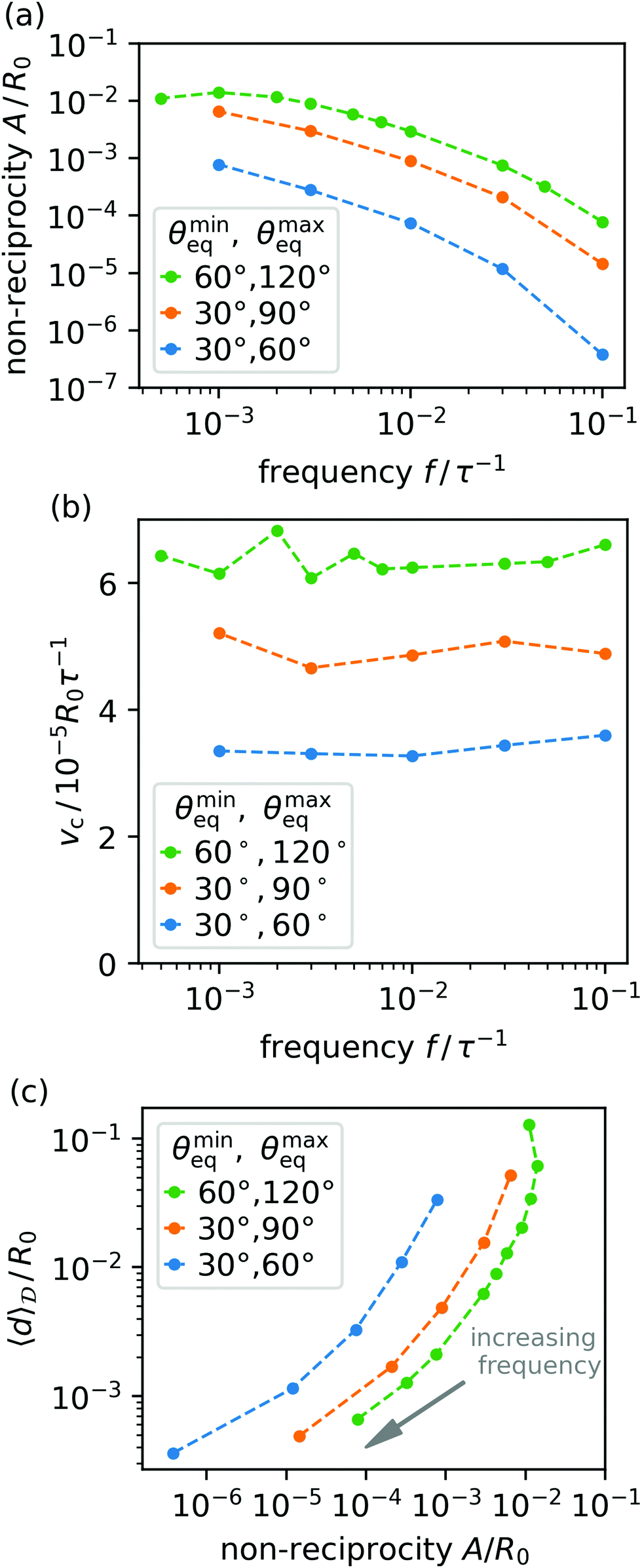 | ||
Fig. 7 Shape non-reciprocity A (a) and pumping velocity vc = f〈d〉![[scr D, script letter D]](https://www.rsc.org/images/entities/char_e523.gif) (b) as a function of oscillation frequency f determined for the three combinations of θmineq and θmaxeq (colored points with dashed lines to guide the eye, see legend). (c) Displacement 〈d〉 plotted directly against A for the same combinations, with an arrow indicating the direction of increasing f. (b) as a function of oscillation frequency f determined for the three combinations of θmineq and θmaxeq (colored points with dashed lines to guide the eye, see legend). (c) Displacement 〈d〉 plotted directly against A for the same combinations, with an arrow indicating the direction of increasing f. | ||
We can directly understand the non-zero values for A by considering the basic mechanisms driving the droplet. When wettability changes, it gives rise to uncompensated Young forces52 at the contact line. The contact line starts to move, which brings θdyn closer to θeq and relaxes the Young forces. At the same time, the free surface is bent locally thereby introducing uncompensated surface stresses in the vicinity of the contact line. Those stresses redistribute liquid inside the droplet and eventually affect droplet height h. So, while θdyn adjusts directly to the changes in wettability, the effect on h is mediated by the initiated flow and, therefore, delayed.
In the quasistatic limit, f → 0, that delay becomes negligible relative to f; contact angle and height oscillate in synchrony and the droplet's behavior approaches the spherical cap model, eqn (16). In the limit f → ∞ the surface stresses relax not by redistributing liquid, but because wettability quickly returns to its original value, thereby eliminating the uncompensated Young forces before the contact line moves significantly. Here, the droplet hardly oscillates and thereby approaches a static spherical cap shape. So, in both limits the droplet assumes spherical shapes and only intermediate frequency values f cause a significant deviation from this form.
We now investigate the liquid displacement d(r0) inside the droplet in more depth. To show the link between non-reciprocity and displacement quantitatively, we consider the median pumping speed vc = f〈d〉 w.r.t. the interior of the droplet, i.e., the 50th percentile value of the spatial distribution of d = |d(r0)| multiplied by frequency f. In Fig. 7(b) we observe that vc remains constant for all f with some fluctuations which means it is purely determined by the material properties of the liquid and substrate and not the oscillation frequency. We already mentioned since the spherical-cap model only has a single degree of freedom, it cannot exhibit any circulatory pumping according to the scallop theorem. So, just like the non-reciprocity A, the non-zero median pumping speed vc also shows that the spherical cap model cannot completely describe the droplet's behavior for small f. However, we expect that vc eventually tends to zero since for sufficiently slow motion of the contact line, the droplet will go through a sequence of spherical-cap shapes. Constraints in the simulation time make it impossible to reach the limit f → 0. However, we observe in Fig. 6 and the inset that for f < 10−2τ−1 the distance between the two halves of the closed trajectories decreases with decreasing f such that the area A and therefore also vc should ultimately vanish. Note, an analogous behavior was observed, for example, in simulations of the one-armed microswimmer.53 When its flexible flagellum beats quickly, it bends due to frictional forces and thereby moves nonreciprocally. But when it beats very slowly, it behaves like a rigid rod and thus moves reciprocally and the microswimmer cannot swim forward.
Because the net circulation occurs in the limit of low Reynolds numbers, as shown in Section 2, inertial effects can be ruled out a priori as its cause. Inertia is relevant in phenomena such as microstreaming,54 where sometimes fluid circulation is observed. Furthermore, because eqn (2) are instantaneous, i.e., they do not contain time derivatives, acoustic excitations also do not play a role in our findings. Rather, we can clearly point to the non-reciprocal shape change of the droplet as the reason that underlies the net circulation.
Finally, in Fig. 7(c) we relate the median displacement 〈d〉 directly to the non-reciprocity A and identify a non-linear relation. We checked that the scaling from Section 3.1, derived from the spherical cap model, does not produce a master curve for either A or 〈|d|〉. This corroborates further that the spherical cap model is inapplicable for these quantities.
3.3 Oscillations of nonuniform wettability profiles
We now extend our investigation to oscillating nonuniform patterns of wettability. Specifically, we choose a pattern where the wettability varies periodically along the contact line of the droplet. As an example, we take the six-fold pattern illustrated in Fig. 8, where the equilibrium contact angle is modulated in space and time: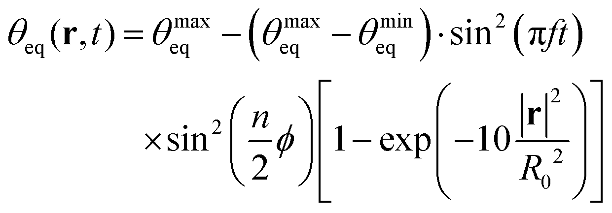 | (24) |
cosϕ, rsinϕ, 0)T and n = 6. The droplet initially sits with its base area centered at r = 0. In an experiment, an equivalent light intensity pattern can be realized with Laguerre–Gauss laser modes.55
 | ||
| Fig. 8 Snapshot of a droplet on a substrate with a nonuniform wettability pattern with six-fold symmetry. The equilibrium contact angles varies between θmineq = 60° and θmaxeq = 120°. | ||
After an initial transient behavior, the droplet settles into steady oscillations analogous to the initial behavior in Section 3.1. However, in this case the droplet shape is not axisymmetric but instead it follows the six-fold symmetry of the wettability pattern. A snapshot of the droplet shape is presented in Fig. 8 and the whole dynamics can be seen in a Video in M04 (ESI†).
To study the steady oscillations quantitatively, we introduce the 6th harmonic mode a6 of the dynamic contact angle along the contact line,
 | (25) |
 | ||
| Fig. 9 Absolute susceptibility |χ| and phase shift Δφ (inset) as a function of oscillation frequency f in units of f0 = τ0−1 determined in the simulations for two combinations of θmaxeq and θmineq (coloured crosses and dots with solid lines to guide the eye, see legend). The dashed grey lines indicate the prediction of the linear model in eqn (18) and (19), respectively. | ||
As before in Section 3.2, we study the periodic deformation of the droplet by combining two aspects of its shape, a6 and the droplet height h. For steady oscillations we display closed-loop trajectories for several frequencies f in Fig. 10 and observe that their extent in the h-a6 plane increases in all directions as f decreases. This is unlike the enclosed area for uniform wettability in Fig. 6, which decreased for f < 10−3τ−1.
 | ||
| Fig. 10 Closed trajectories in configuration space projected onto the h-a6 plane for various frequencies f (see legend) for θmineq = 60° and θmaxeq = 120°. | ||
As mentioned before in Section 3.2, an increase in the enclosed area in configuration space means that the shape dynamics deviates more strongly from a reciprocal motion. While for the oscillating uniform pattern we have the sperical cap model as a reference, which shows reciprocal dynamics and which the droplet should approach for sufficiently small f, such a reference is missing for the nonuniform patterns and the droplet dynamics need not be reciprocal in the limit of small f.
4 Conclusions
We have studied liquid droplets on substrates with oscillating wettability focussing on their shape and internal fluid flow. When starting the wettability oscillations, the droplets go through a transient period, where the mean contact angle relaxes, and then settles into steady oscillations w.r.t. shape and contact angle. The amplitude of the contact-angle oscillations decreases with increasing frequency and, of course, increases with the amplitude of the wettability oscillations. At small frequencies the amplitude and phase shift of the oscillations follow the linearized and parameter-free spherical-cap model, while they deviate from it for larger frequencies, where the free droplet surface deviates noticeably from a spherical cap. As a result, amplitude and phase shift fall onto a master curve for small frequencies when we scale frequency with the decay time of the linearized spherical-cap model.Upon further analysis of the droplet shape and the interior flow field, we have found that also for small frequencies the spherical cap model cannot account for the droplet's behavior completely. The droplet shape deforms non-reciprocally which becomes evident when tracking its contact angle and height over time. The non-reciprocal dynamics of the droplet shape gives rise to a time-dependent internal flow field which displaces point-like tracer particles over the course of a full period of oscillation rather than returning them to their original position. Notably, the volume median of the displacement per period, the pumping speed, is constant w.r.t. frequency in the investigated frequency range and only depends on material properties of the droplet and substrate. Most importantly, the circulatory pumping of fluid inside the droplet is captured only by solving the full equations of Stokes flow, which we did using the boundary element method.
Repeating the same analysis for a droplet which is controlled by an oscillating nonuniform pattern of wettability with six-fold symmetry, we observed a very similar behavior. The droplet settles into steady oscillations, the amplitude of which decreases when the oscillation frequency increases. Furthermore, its shape deforms non-reciprocally, which becomes more pronounced at smaller oscillation frequencies.
Experiments so far have investigated the droplet's response when the wettability is switched between two values, for example in ref. 5, 7, 8, 11 and 12. They demonstrated that large changes in wettability can be achieved by exposing appropriately prepared substrates to light for sufficiently long times and they only measured the droplet's new equilibrium shape without monitoring the temporal evolution towards the final shape. Our investigation applies oscillations in wettability over a large range of frequencies and explicitely monitors the droplet's dynamic ranging from the quasistatic case to fast oscillations where the droplet can never fully relax to its equilibrium shape. Early experiments, e.g. in ref. 2, showed that both, the fraction of isomerized molecules in a light-switchable monolayer (of which wettability is a function) and the spreading and contraction of the droplet, can be measured independently in time. Analogously, for light-switchable structured substrates, e.g. consisting of switchable pillars,9 the surface topology can be monitored in time. Future experiments, which build on these methods, will find in our investigation a guiding prediction of the droplet response beyond the quasi-static case of slow oscillations.
Because in our investigation the circulation is stimulated from outside by oscillations in wettability, it provides a mechanism for controlling the transport and possibly mixing of solutes inside the droplet. Internal transport through external stimuli has been used, for example, to precisely deposit a solute during the evaporation of droplets with light-responsive surfactants.56 Note, however, that depending on the contact angle evaporation contributes to and disturbs the flow field close to a moving contact line.57 By designing specific spatio-temporal wettability patterns, such as moving steps in wettability,24 we envisage to similarly control the precise transport of solutes through substrates with switchable wettability.
Conflicts of interest
There are no conflicts to declare.Acknowledgements
We acknowledge financial support from DFG (German Research Foundation) via Collaborative Research Center 910.Notes and references
- D. Bonn, J. Eggers, J. Indekeu, J. Meunier and E. Rolley, Rev. Mod. Phys., 2009, 81, 739 CrossRef CAS.
- K. Ichimura, S. Oh and M. Nakagawa, Science, 2000, 288, 1624 CrossRef CAS PubMed.
- T. Seki, Bull. Chem. Soc. Jpn., 2018, 91, 1026–1057 CrossRef CAS.
- R. Malinowski, I. P. Parkin and G. Volpe, Chem. Soc. Rev., 2020, 49, 7879 RSC.
- N. Delorme, J.-F. Bardeau, A. Bulou and F. Poncin-Epaillard, Langmuir, 2005, 21, 12278 CrossRef CAS PubMed.
- B. C. Bunker, Mater. Sci. Eng., R, 2008, 62, 157 CrossRef.
- J. Lahann, S. Mitragotri, T. Tran, H. Kaido, J. Sundaram, I. S. Choi, S. Hoffer, G. A. Somorjai and R. Langer, Science, 2003, 299, 371 CrossRef CAS PubMed.
- W. Jiang, G. Wang, Y. He, X. Wang, Y. An, Y. Songa and L. Jiang, Chem. Commun., 2005, 3550 RSC.
- F. Pirani, A. Angelini, F. Frascella, R. Rizzo, S. Ricciardi and E. Descrovi, Sci. Rep., 2016, 6, 31702 CrossRef CAS PubMed.
- S. L. Oscurato, F. Borbone, P. Maddalena and A. Ambrosio, ACS Appl. Mater. Interfaces, 2017, 9, 30133–30142 CrossRef CAS PubMed.
- H. S. Lim, J. T. Han, D. Kwak, M. Jin and K. Cho, J. Am. Chem. Soc., 2006, 128, 14458 CrossRef CAS PubMed.
- H. S. Lim, D. Kwak, D. Y. Lee, S. G. Lee and K. Cho, J. Am. Chem. Soc., 2007, 129, 4128 CrossRef CAS PubMed.
- E. Samiei, M. Tabrizian and M. Hoorfar, Lab Chip, 2016, 16, 2376–2396 RSC.
- D. Mampallil and H. B. Eral, Adv. Colloid Interface Sci., 2018, 252, 38–54 CrossRef CAS PubMed.
- H. P. Greenspan, J. Fluid Mech., 1978, 84, 125 CrossRef.
- F. Brochard, Langmuir, 1989, 5, 432 CrossRef CAS.
- K. B. Glasner, J. Comput. Phys., 2005, 207, 529 CrossRef.
- A. Moosavi, M. Rauscher and S. Dietrich, J. Chem. Phys., 2008, 129, 044706 CrossRef CAS PubMed.
- S. Dietrich, M. N. Popescu and M. Rauscher, J. Phys.: Condens. Matter, 2005, 17, S577 CrossRef CAS.
- O. Kašpar, H. Zhang, V. Tokárová, R. I. Boysen, G. R. Suñé, X. Borrise, F. Perez-Murano, M. T. W. Hearn and D. V. Nicolau, Lab Chip, 2016, 16, 2487 RSC.
- N. Savva, D. Groves and S. Kalliadasis, J. Fluid Mech., 2019, 859, 321 CrossRef CAS.
- S. Engelnkemper, S. V. Gurevich, H. Uecker, D. Wetzel and U. Thiele, in Continuation for Thin Film Hydrodynamics and Related Scalar Problems, ed. A. Gelfgat, Springer International Publishing, Cham, 2019, pp. 459–501 Search PubMed.
- U. Thiele, K. John and M. Bär, Phys. Rev. Lett., 2004, 93, 027802 CrossRef PubMed.
- J. Grawitter and H. Stark, Soft Matter, 2021, 17, 2454 RSC.
- P.-G. de Gennes, Rev. Mod. Phys., 1985, 57, 827 CrossRef CAS.
- C. Huh and L. E. Scriven, J. Colloid Interface Sci., 1971, 35, 85 CrossRef CAS.
- O. V. Voinov, Fluid Dyn., 1976, 11, 714 CrossRef.
- X. Noblin, A. Buguin and F. Brochard-Wyart, Eur. Phys. J.: Spec. Top., 2009, 166, 7–10 Search PubMed.
- S. Sudo, A. Goto, H. Kuwano, Y. Hamate, T. Yano and K. Hoshika, J. Jpn. Soc. Exp. Mech., 2010, 10, s38–s45 Search PubMed.
- T. Singla, D. K. Verma, J. F. Tovar, A. Figueroa, F. Vázquez, F. B. Yousif and M. Rivera, AIP Adv., 2019, 9, 045204 CrossRef.
- G. F. Teletzke, H. T. Davis and L. Scriven, Rev. Phys. Appl., 1988, 23, 989–1007 CrossRef.
- A. Oron, S. H. Davis and S. G. Bankoff, Rev. Mod. Phys., 1997, 69, 931 CrossRef CAS.
- M. N. Popescu, G. Oshanin, S. Dietrich and A.-M. Cazabat, J. Phys.: Condens. Matter, 2012, 24, 243102 CrossRef CAS PubMed.
- U. Thiele, Colloids Surf., A, 2018, 553, 487 CrossRef CAS.
- M. J. de Ruijter, J. De Coninck, T. D. Blake, A. Clarke and A. Rankin, Langmuir, 1997, 13, 7293 CrossRef CAS.
- T. M. Squires and S. R. Quake, Rev. Mod. Phys., 2005, 77, 977 CrossRef CAS.
- D. Baigl, Lab Chip, 2012, 12, 3637 RSC.
- Q. Dai, W. Huang, X. Wang and M. Khonsari, Tribol Int., 2021, 154, 106749 CrossRef.
- S. Kim and S. J. Karrila, Microhydrodynamics, Dover Publications, Mineola/NY, 2005 Search PubMed.
- C. Pozrikidis, Boundary integral and singularity methods for linearized viscous flow, Cambridge University Press, Cambridge, 1992 Search PubMed.
- S. J. Bolaños and B. Vernescu, Phys. Fluids, 2017, 29, 057103 CrossRef.
- R. G. Cox, J. Fluid Mech., 1986, 168, 169 CrossRef CAS.
- H. K. Moffatt, J. Fluid Mech., 1964, 18, 1–18 CrossRef.
- H. B. Eral, D. J. C. M. 't Mannetje and J. M. Oh, Colloid Polym. Sci., 2013, 291, 247 CrossRef CAS.
- J. H. Snoeijer and B. Andreotti, Annu. Rev. Fluid Mech., 2013, 45, 269 CrossRef.
- C. Tsitouras, Comput. Math. Appl., 2011, 62, 770 CrossRef.
- J. T. Katsikadelis, The Boundary Element Method for Engineers and Scientists, Elsevier, 2nd edn, 2016 Search PubMed.
- J. D. McGraw, T. S. Chan, S. Maurer, T. Salez, M. Benzaquen, E. Raphaël, M. Brinkmann and K. Jacobs, Proc. Natl. Acad. Sci. U. S. A., 2016, 113, 1168 CrossRef CAS PubMed.
- T. S. Chan, J. D. McGraw, T. Salez, R. Seemann and M. Brinkmann, J. Fluid Mech., 2017, 828, 271 CrossRef CAS.
- Y. A. Pityuk, O. A. Abramova, N. A. Gumerov and I. S. Akhatov, Math. Models Comput. Simul., 2018, 10, 209 CrossRef.
- E. M. Purcell, Am. J. Phys., 1977, 45, 3 CrossRef.
- T. Young, Philos. Trans. R. Soc., 1805, 95, 65–87 CrossRef.
- E. Gauger and H. Stark, Phys. Rev. E, 2006, 74, 021907 CrossRef PubMed.
- J. Jalal and T. S. H. Leong, Fluids, 2018, 3, 93 CrossRef CAS.
- L. Allen, M. W. Beijersbergen, R. J. C. Spreeuw and J. P. Woerdman, Phys. Rev. A: At., Mol., Opt. Phys., 1992, 45, 8185 CrossRef PubMed.
- S. N. Varanakkottu, M. Anyfantakis, M. Morel, S. Rudiuk and D. Baigl, Nano Lett., 2016, 16, 644 CrossRef CAS PubMed.
- H. Gelderblom, O. Bloemen and J. H. Snoeijer, J. Fluid Mech., 2012, 709, 69 CrossRef CAS.
Footnotes |
| † Electronic supplementary information (ESI) available: We provide four example movies. They show a droplet on a substrate, the wettability of which oscillates with frequency f = 10−3. The first three movies show a droplet on a substrate with uniform wettability. Movie M01 corresponds to an oscillation with θmineq = 60° and θmaxeq = 120°, movie M02 corresponds to θmineq = 45° and θmaxeq = 90°, and movie M03 corresponds to θmineq = 30° and θmaxeq = 60°. The final Movie M04 corresponds to the nonuniform wettability profile given by eqn (24) with θmineq = 60° and θmaxeq = 120°. See DOI: 10.1039/d1sm01113h |
| ‡ Note that due to the discretization of the droplet surface, all θdyn of the simulated curves are systematically shifted downwards by a small angle. Otherwise, they should center on the dashed line. |
| This journal is © The Royal Society of Chemistry 2021 |