 Open Access Article
Electrochemical synthesis of core–shell nanoparticles by seed-mediated selective deposition†
Joon Ho
Park
a,
Seon-Mi
Jin
b,
Eunji
Lee
 b and
Hyun S.
Ahn
 *a
*a
aDepartment of Chemistry, Yonsei University, 50 Yonsei-ro, Seodaemun-gu, Seoul, 03722, Republic of Korea. E-mail: ahnhs@yonsei.ac.kr
bSchool of Materials Science and Engineering, Gwangju Institute of Science and Technology (GIST), 123 Cheomdangwagiro, Bukgu, Gwangju, Republic of Korea. E-mail: eunjilee@gist.ac.kr
First published on 8th September 2021
Abstract
Conventional solvothermal synthesis of core–shell nanoparticles results in them being covered with surfactant molecules for size control and stabilization, undermining their practicality as electrocatalysts. Here, we report an electrochemical method for the synthesis of core–shell nanoparticles directly on electrodes, free of surfactants. By implementation of selective electrodeposition on gold cores, 1st-row transition metal shells were constructed with facile and precise thickness control. This type of metal-on-metal core–shell synthesis by purely electrochemical means is the first of its kind. The applicability of the nanoparticle decorated electrodes was demonstrated by alkaline oxygen evolution catalysis, during which the Au–Ni example displayed stable catalysis with low overpotential.
Introduction
Nanoparticle research in the past half-century has spearheaded numerous important technological advances.1,2 The early stage of synthetic development focused on the control of size and shape;3 however, as the field matured, complex structures such as core–shell and Janus became desirable synthetic targets for the control of magnetic susceptibility4 and surface catalysis.5,6 In particular, core–shell nanoparticles are valuable in a wide range of fields, including bio-nanotechnology and optomagnetics, due to the independent control of the properties of the core and the shell.7–9Core–shell nanoparticles have also been actively studied as electrocatalyst candidates for reactions pertinent to energy storage and release, such as the hydrogen evolution reaction (HER), the oxygen reduction reaction (ORR), and the oxygen evolution reaction (OER). These reactions classically require expensive and rare metals such as Pt, Pd, and Ir as catalysts,10,11 and much research effort has been devoted to adopting the core–shell design with an inexpensive core and a thin shell of precious metal for the optimal cost and atom efficiencies, while maintaining the catalytic performance of rare metals. While a handful of successful studies resulted in materials exhibiting the desired properties,12,13 conventional solvothermal methods result in particles passivated by surfactants. It is well known that the electrochemical activity of surfactant-covered nanoparticles is low.14,15 For electrocatalytic applications, a costly pretreatment process (thermolysis or reduction of surfactants to carbonaceous matter in H2) is mandated.16 To bypass this problem, direct electrochemical syntheses of surfactant-free nanomaterials have recently been developed;17–19 however, investigations toward electrochemical synthesis of core–shell nanoparticles are rare to date.20 A handful of electrochemical syntheses of core–shell nanoparticles were demonstrated by Compton and coworkers; however, direct visualization of the product was not conducted by electron microscopy, therefore allowing uncertainties in the quantification of the dimensions of the particles.21,22 Furthermore, a few other examples of electrochemically prepared core–shell structures consist of semiconductor shells on metal cores, but because their formation was concluded by a charge transfer-induced chemical process,23,24 control over the thickness of the grown shell was difficult. Because recent studies emphasize the importance of the interactions between surface and sub-surface species, particularly with regards to electrocatalysis of complex reactions (e.g., CO2 reduction and ammonia oxidation),25–27 synthetic schemes for the direct electrochemical synthesis of surfactant-free core–shell nanomaterials with controllable shell thickness are highly desired.
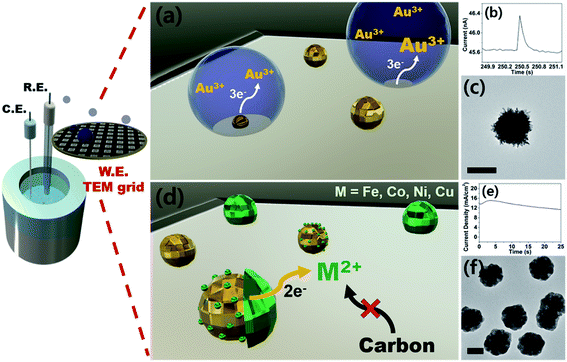
Therefore, here we report an electrochemical synthetic strategy towards core–shell nanoparticles and tandem visualization of the products by electron microscopy. By means of seed-mediated selective electrodeposition, we were able to construct shells of various metals on gold cores. Because the synthesis utilizes direct electroreduction without the involvement of a chemical reaction, the thickness of the shell can be precisely controlled by modulating charge passed during synthesis. To the best of our knowledge, this is one of the rare examples of metal-on-metal core–shell nanoparticle preparation by purely electrochemical means, in the absence of surfactants. Also worth noting is that we demonstrate 1st-row transition metal shells (Fe, Co, Ni, and Cu), the synthesis of which in their metallic forms is difficult due to their proclivity to form oxyhydroxides.28–30 As with our previous studies,18,19 we utilized TEM grids as working electrodes for direct monitoring of the synthesis process by electron microscopy. The prepared core–shell nanoparticles were evaluated as catalysts for the OER, with the best sample (Au–Ni) exhibiting superior catalysis compared to that of Pt/C and a small overpotential more anodic than that of IrO2.
Results and discussion
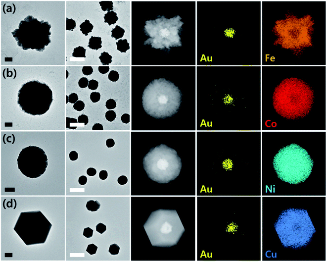
Prior to the synthesis experiments, we confirmed the reduction potentials of a set of 1st-row transition metals including Fe, Co, Ni, and Cu on gold and glassy carbon (GC) electrodes (Fig. S1†). There was a significant difference in the onset potentials of metal deposition between gold and GC for all metals tested; therefore, we designed selective deposition of the 1st-row transition metal shells on Au seeds without incurring reaction on carbon.Gold nanoparticle seeds were synthesized on a TEM grid at −0.4 V (vs. Ag/AgNO3) using aqueous nanodroplets (AnDs) as precursor vessels similar to our previous studies,18 and were visually inspected via TEM (Fig. S2†). Briefly, as AnDs suspended in chloroform (0.2 M TBAP) collided on the TEM grid working electrode, gold nanoparticles were synthesized by reduction of the gold precursor (10 mM HAuCl4, in 600 nm diameter AnDs, 1500 s synthesis time). Because the reaction halts upon full consumption of the gold precursor inside an AnD, no surfactant is required for growth termination (the synthesis process is also independently observable by amperometry; Fig. 1b). In our previous works we have shown that on average, one AnD resulted in one nanoparticle.18 It is noticed that nanoparticles of 210 ± 20 nm diameter were evenly distributed (Fig. S2†). A relatively large particle size was chosen for ease of analysis for this proof-of-concept study; however, our synthetic methodology allows facile control of the resultant nanomaterial size for technical applications.18 For the demonstration of the ease of nanoparticle dimension control and the utility of the developed synthetic protocol, particles smaller (50 nm core and 25 nm shell) and larger (400 nm core and 300 nm shell) than those employed in the described study were prepared (Fig. S3†). The synthesis of core–shell nanoparticles was possible regardless of dimensions, and all subsequent investigations in this article were carried out on ca. 200 nm core variants. The density of particles observed in TEM analysis was 5 × 10⁷ nanoparticles per cm2, in reasonable agreement with 1.2 × 10⁷ nanoparticles per cm2 calculated from AnD amperometry data during synthesis (see ESI† for detailed calculations). Subsequent shell deposition was completed by chronoamperometry of the gold core-decorated working electrode in a replaced deposition bath (100 mM FeSO4, 100 mM CoSO4, 100 mM NiSO4, and 100 mM CuSO4 in water; 0.5 M H3BO3 and 0.1 M K2SO4 were employed as supporting electrolytes). A metal-specific potential was applied for selective deposition on the gold cores (−0.55 V for Co, −0.6 V for Ni, −0.7 V for Fe, and 0.7 V for Cu vs. RHE; see Fig. S1†), and the experiment was terminated after the deposition of a shell of the desired thickness by control of the passed charge (vide infra; Fig. S4†). By applying potential for ca. 150 s, surfactant-free hemispherical core–shell nanoparticles were yielded as the final products as shown in Fig. 2 and S4,† with average diameters of ca. 700 ± 100 nm (shell thickness of ca. 230 nm). From the elemental mapping data, it is clear that gold nanoparticles constitute the cores and the 1st-row transition metal shells perfectly cover around them. Inspection at the single particle level (in TEM and HAADF-STEM) suggests that Au–Fe, Au–Co, and Au–Ni were constructed with polycrystalline shells, whereas the copper shell in Au–Cu was single crystalline with clear edges. Selected area electron diffraction patterns (Fig. S4†) also confirmed the phases, exhibiting ring patterns for the polycrystalline samples and discrete spots for the single crystal. The electron diffraction patterns and elemental ratios from energy dispersive X-ray spectroscopy (Fig. S5 and Table S1†) together suggest that Au–Fe, Au–Co, and Au–Ni featured metallic shells with little oxidation, whereas Au–Cu exhibited a more severe level of oxidation, presumably due to air exposure during sample handling and transport. The electrochemical preparation of metallic Co, Ni, and Fe nanomaterials is remarkable because the reduction potentials of the aqueous dications of the three metals are similar to the HER onset potential on even the most subdued carbon electrode (Fig. S1†).28 Therefore, researchers investigated the HER as a competing reaction in an attempt to electrodeposit 1st-row transition metals. Hydrogen evolution increased the local pH near the electrode, and subsequently led to deposition of metal oxyhydroxide particles of ill-defined shape and size.26 It is quite encouraging that we were able to electrochemically synthesize metallic Co, Ni, and Fe nanoparticles in this work by control of the deposition bath and implementation of selective reduction on gold cores.
Copper on the other hand undergoes reduction at much more anodic potentials, far separated from that required to incur the HER. Therefore, investigation of its electrodeposition behavior was possible in a wider range of potentials. Synthesis in a more cathodic potential range (0.8 V to 0.7 V) yielded single crystalline Au–Cu nanoparticles as shown in Fig. 2; however, polycrystalline copper shells were found at less cathodic potentials (0.95 V; Fig. S6†). Presumably more reducing potential is required for single crystalline shell growth, and in the case of copper, control of crystallinity of the shell was possible by potential modulation. Transition to a single crystalline shell was not observed for Co, Ni, and Fe in the narrow potential range available avoiding the HER. Synthesis of Au–Cr and Au–Mn was also attempted, but the reduction potentials of the metal ions were too cathodic, such that it seemed to be significantly disturbed by the HER and led to oxyhydroxide formation instead (Fig. S7†).
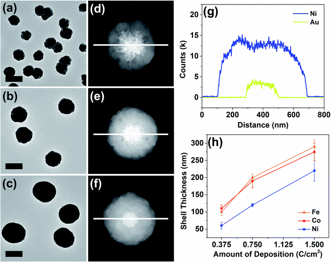
The thickness of the particle shells was precisely controllable as revealed in a representative set of examples in Fig. 3. Means to independently control the dimensions of the core and the shell are important in nanomaterial synthesis. In the case of Au–Ni, HAADF-STEM and elemental line scans clearly display a progression of shell growth from Fig. 3a to c. These samples of variable shell thickness were reproducibly generated in a precisely controlled fashion by control of the passed charge in synthetic chronoamperometry (Fig. S4†). In the Au–Ni example, 0.375 C cm−2 yielded 60 ± 10 nm of shell, 0.75 C cm−2 resulted in 120 ± 5 nm, and 1.5 C cm−2 generated 220 ± 30 nm shells on the gold seeds. Particle-to-particle deviation in the shell thickness was very small, and the proportional growth as a function of deposition charge was linear. Similar trends were found for cobalt and iron (see also Fig. S8 and S9†), representing that the shell thickness control is feasible regardless of the metal with good precision. The difference in the deposition rate across metals can be attributed to dissimilar rates of the competing HER, which also consumes a certain proportion of the current in synthetic amperometry. Although the deposition rate of copper is not comparable to those of nickel, cobalt, and iron due to the drastic difference in the deposition potential, the Au–Cu shell thickness was also controllable in a similar fashion by control of the passed charge (Fig. S10†).
A representative Au–Ni particle was analyzed by 3D TEM tomography for the characterization of its stereographic morphology and investigation into the imperfections in the shell. Because varying degrees of shell imperfections may yield electrochemical property modification in core–shell particles,31 a more careful investigation into the synthesized particles in this work was required. The 3D tomographic images and the reconstructed hologram of the Au–Ni particle (Fig. S11 and video ESI†) reveal that the core–shell nanoparticle synthesized from the method reported here was composed of a concrete 1st-row transition metal shell with no cracks, and was spherical in shape with anisotropic distortion generated by the planar electrode on which the growth process initiated.
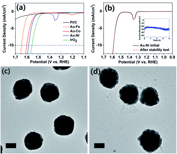
The electrochemically synthesized core–shell nanoparticles were evaluated as electrocatalysts for the alkaline OER (reaction in aqueous solution containing 1 M KOH). Oxygen evolution is an important reaction in renewable energy technology because water is the only viable electron source to drive fuel-forming reductions on large scales.11,32 Typical electrodes were prepared on a GC disk by identical procedures to that used to prepare particles on a TEM grid, at the same particle density. Shell thicknesses were chosen at 0.375 C cm−2 level. When area normalized, the OER catalysis of the nanoparticle decorated GC and TEM grid (Fig. S12†) displayed identical behavior. The catalyst cast GC was prepared for comparison of the activity against typical benchmarks (Pt/C and IrO2), and those on TEM grids were used for tracking of the structural evolution post catalysis. The Pt/C and IrO2 electrodes were used as benchmarks, and all electrodes compared in this work were composed of ca. 0.1 mg cm−2 of catalyst metal (see ESI† for details). As seen in Fig. 4a, the IrO2 electrode exhibited 10 mA cm−2 of OER catalytic current at 1.55 V (vs. RHE; all potentials referenced to RHE for the OER), similar to those reported in the literature.33,34 The platinum-based electrode displayed meager catalysis and did not surpass 2.5 mA cm−2 at 1.7 V. The Au–Fe decorated electrode displayed inferior catalysis compared to Au–Co and Au–Ni, and more importantly exhibited poor stability due to iron dissolution (see Fig. S13†). The core–shell nanoparticle electrodes with nickel and cobalt shells exhibited similar catalytic activities, requiring ca. 1.6 V to reach OER currents of 10 mA cm−2. This finding is quite noteworthy because catalysts composed of relatively cheap metals such as nickel and cobalt required less than 50 mV overpotential at the same current compared to IrO2, the benchmark catalyst. It is also worth noting that our catalyst electrodes were prepared by electrochemical methods, which require no harsh or expensive pretreatment processes for the material-to-electrode transition. Upon careful inspection of the catalysis voltammograms of Au–Co and Au–Ni electrodes, anodic peaks (at 1.2 V for Au–Co and 1.35 V for Au–Ni) were observed, corresponding to hydroxide to oxyhydroxide transitions of cobalt and nickel in alkaline solutions.35,36 Cobalt oxide is known for good OER catalysis;37 however, the observation of similar levels of reactivity from nickel oxide is unusual. Literature precedents found that doping of iron into nickel oxide improved OER catalysis;38–40 however, the Au–Ni catalysts exhibited no iron content, confirmed by ICP-OES (Table S2†). Therefore we assign the core–shell design as the reason for enhanced catalysis by nickel, and the exact nature of the interactions between the core and the shell is under further investigation.
Oxygen evolution catalysis by the Au–Ni electrode was maintained with a stable current (at 1.65 V, Fig. 4b) for at least four hours, and the nanoparticles were evaluated under TEM for structural evolution following extended OER. The particle morphology was identical before and after catalysis (Fig. 4c and d), and the elemental ratios and distributions were also maintained suggesting that a thin nickel oxide layer passivated the metallic nickel shell, preventing its complete oxide conversion. In contrast, the Au–Co sample underwent severe deformation during extended OER (Fig. S14†). Post catalytic TEM images revealed transformation of the cobalt shell into platelet-like particles, and full conversion to oxide was suggested by the elemental ratio devoid of cobalt in the EDS spectrum. Dissolution and redeposition of cobalt species during the OER is a well-known phenomenon as Co2+ and Co4+ are cycled.41–43 The cobalt-based electrode experienced an increase in the OER overpotential of ca. 30 mV after the durability test and the subsequent loss of the core–shell structure (Fig. S14 and S15†), indirectly suggesting that the core–shell architecture may have contributed to the extraordinary catalytic activity of Au–Ni.
Analysis of the Tafel region of the OER voltammograms of various catalyst electrodes in this work revealed that the Au–Ni nanoparticle decorated electrode exhibited the smallest (68 mV dec−1) Tafel slope in a durable fashion (Fig. S16†). The Tafel slope exhibited by Au–Ni nanoparticles was similar to that of IrO2 (70 mV dec−1), suggesting their similar OER mechanism. Commercial Ni nanoparticles of 100 nm diameter were also investigated for the OER, and the results were compared to that of Au–Ni (Fig. S17†). Clearly superior OER catalysis was demonstrated by Au–Ni compared to that of Ni nanoparticles (despite the smaller size of the commercial Ni particles), suggesting that the core–shell structure advantageously affects the OER performance when the structural integrity is maintained during catalysis (vide supra).
In order to demonstrate the scale-up possibility of the synthetic method introduced in this article, we prepared a number of large (2 cm2) glassy carbon plates and decorated them with Au–Ni nanoparticles. Nanoparticles with similar size and compositions to those on TEM grids were yielded (Fig. S18†), and the OER electrocatalysis was also similar. In particular, currents in excess of 50 mA were generated at modest overpotentials (Fig. S18†), demonstrating that the synthetic protocol in this work is more than capable of scale-up to practical dimensions.
Conclusions
In this article, we report a novel electrochemical synthesis of surfactant-free core–shell nanoparticles. Transition metals that are difficult to obtain in their metallic forms were synthesized by clever use of a seed-mediated selective deposition method. The thickness of the shells was easily and precisely controllable, and the nanoparticle decorated electrodes were functional as catalysts without the need for pretreatment. The electrode with Au–Ni nanoparticles exhibited good OER catalysis, requiring only a small overpotential compared to the IrO2 benchmark catalyst, and also displayed durability and morphological integrity. The synthetic methodology introduced here, especially with wide selection of applicable metals and modular control of the core/shell properties, should diversify the electrocatalyst options for various reactions.Data availability
All data supporting the results and conclusions are available within this paper and the ESI.†Author contributions
J. H. P. and H. S. A. designed the project, J. H. P. performed all of the experiments. J. H. P. and H. S. A. analysed the results and prepared the manuscript. S. M. J. and E. L. conducted 3D TEM tomography experiments and wrote the relevant experimental and discussion sections.Conflicts of interest
There are no conflicts to declare.Acknowledgements
This work was financially supported by the Basic Science Research Program through the National Research Foundation (NRF) of Korea (NRF-2020R1C1C1007409, NRF-2020R1A4A1017737 and NRF-2019M3E6A1064707).Notes and references
- W. J. Stark, P. R. Stoessel, W. Wohlleben and A. Hafner, Chem. Soc. Rev., 2015, 44, 5793–5805 RSC.
- X. Han, K. Xu, O. Taratula and K. Farsad, Nanoscale, 2019, 11, 799–819 RSC.
- A. R. Tao, S. Habas and P. Yang, Small, 2008, 4, 310–325 CrossRef CAS.
- C. S. Levin, C. Hofmann, T. A. Ali, A. T. Kelly, E. Morosan, P. Nordlander, K. H. Whitmire and N. J. Halas, ACS Nano, 2009, 3, 1379–1388 CrossRef CAS PubMed.
- M. Liu, W. Tang, Z. Xie, H. Yu, H. Yin, Y. Xu, S. Zhao and S. Zhou, ACS Catal., 2017, 7, 1583–1591 CrossRef CAS.
- T. Yang, L. Wei, L. Jing, J. Liang, X. Zhang, M. Tang, M. J. Monteiro, Y. Chen, Y. Wang, S. Gu, D. Zhao, H. Yang, J. Liu and G. Q. M. Lu, Angew. Chem., Int. Ed., 2017, 56, 8459–8463 CrossRef CAS PubMed.
- C. W. Hsu, B. Zhen, W. Qiu, O. Shapira, B. G. DeLacy, J. D. Joannopoulos and M. Soljačić, Nat. Commun., 2014, 5, 3152–3157 CrossRef PubMed.
- R. G. Chaudhuri and S. Paria, Chem. Rev., 2012, 112, 2373–2433 CrossRef PubMed.
- R. Haag, Angew. Chem., Int. Ed., 2004, 43, 278–282 CrossRef CAS PubMed.
- N. Dubouis, Chem. Sci., 2019, 17, 9165–9181 RSC.
- M. Tahir, L. Pan, F. Idrees, X. Zhang, L. Wang and J.-J. Zou, Nano Energy, 2017, 37, 136–157 CrossRef CAS.
- C.-W. Lai, Y.-H. Wang, B. P. Uttam, Y.-C. Chen, J.-K. Hsiao, C.-L. Liu, H.-M. Liu, C.-Y. Chen and P.-T. Chou, Chem. Commun., 2008, 5342–5344 RSC.
- Y. W. Lee, M. Kim, Z. H. Kim and S. W. Han, J. Am. Chem. Soc., 2009, 131, 17036–17037 CrossRef CAS PubMed.
- T. Quast, H. B. Aiyappa, S. Saddeler, P. Wilde, Y.-T. Chen, S. Schulz and W. Schuhmann, Angew. Chem., Int. Ed., 2021, 60, 3576–3580 CrossRef CAS PubMed.
- T. M. Benedetti, C. Andronescu, S. Cheong, P. Wilde, J. Wordsworth, M. Kientz, R. D. Tilley, W. Schuhmann and J. J. Gooding, J. Am. Chem. Soc., 2018, 7, 13449–13455 CrossRef PubMed.
- D. Li, C. Wang, D. Tripkovic, S. Sun, N. M. Markovic and V. R. Stamenkovic, ACS Catal., 2012, 2, 1358–1362 CrossRef CAS.
- S. A. Lee, T. H. Lee, C. Kim, M. G. Lee, M.-J. Choi, H. Park, S. Choi, J. Oh and H. W. Jang, ACS Catal., 2018, 8, 7261–7269 CrossRef CAS.
- Y. E. Jeun, B. Baek, M. W. Lee and H. S. Ahn, Chem. Commun., 2018, 54, 10052–10055 RSC.
- J. H. Park and H. S. Ahn, Appl. Surf. Sci., 2020, 504, 144517–144523 CrossRef CAS.
- H. Wang, W. Zhao, Y. Zhao, C.-H. Xu, J.-J. Xu and H.-Y. Chen, Anal. Chem., 2020, 92, 14006–14011 CrossRef CAS PubMed.
- F. W. Campbell, Y.-G. Zhou and R. G. Compton, New J. Chem., 2010, 34, 187–189 RSC.
- Y.-G. Zhou, N. V. Rees and R. G. Compton, Chem. Phys. Lett., 2011, 511, 183–186 CrossRef CAS.
- H. Wang, W. Zhao, C.-H. Xu, H.-Y. Chen and J.-J. Xu, Chem. Sci., 2019, 10, 9308–9314 RSC.
- D. A. Robinson and H. S. White, Nano Lett., 2019, 19, 5612–5619 CrossRef CAS PubMed.
- W. Guo and D. G. Vlachos, Nat. Commun., 2015, 6, 8619–8625 CrossRef CAS PubMed.
- M. Favaro, H. Xiao, T. Cheng, W. A. Goddard, J. Yano and E. J. Crumlin, Proc. Natl. Acad. Sci., 2017, 114, 6706–6711 CAS.
- R. G. Mariano, K. McKelvey, H. S. White and M. W. Kanan, Science, 2017, 358, 1187–1192 CrossRef CAS PubMed.
- Y. E. Jeun, J. H. Park, J. Y. Kim and H. S. Ahn, Chem.–Eur. J., 2020, 26, 4039–4043 CAS.
- Z. Yan, H. Liu, Z. Hao, M. Yu, X. Chen and J. Chen, Chem. Sci., 2020, 11, 10614–10625 RSC.
- A. S. Batchellor and S. W. Boettcher, ACS Catal., 2015, 5, 6680–6689 CrossRef CAS.
- K. Tschulik, K. Ngamchuea, C. Ziegler, M. G. Beier, C. Damm, A. Eychmueller and R. G. Compton, Adv. Funct. Mater., 2015, 25, 5149–5158 CrossRef CAS.
- N.-T. Suen, S.-F. Hung, Q. Quan, N. Zhang, Y.-J. Xu and H. M. Chen, Chem. Soc. Rev., 2017, 46, 337–365 RSC.
- T. Reier, M. Oezaslan and P. Strasser, ACS Catal., 2012, 2, 1765–1772 CrossRef CAS.
- K. A. Stoerzinger, L. Qiao, M. D. Biegalski and Y. Shao-Horn, J. Phys. Chem. Lett., 2014, 6, 1636–1642 CrossRef PubMed.
- T. T. H. Hoang and A. A. Gewirth, ACS Catal., 2016, 6, 1159–1164 CrossRef CAS.
- S. L. Medway, C. A. Lucas, A. Kowal, R. J. Nichols and D. Johnson, J. Electroanal. Chem., 2006, 587, 172–181 CrossRef CAS.
- J. Wang, W. Cui, Q. Liu, Z. Xing, A. M. Asiri and X. Sun, Adv. Mater., 2016, 28, 215–230 CrossRef CAS PubMed.
- D. A. Corrigan, J. Electrochem. Soc., 1987, 134, 377–384 CrossRef CAS.
- H. S. Ahn and A. J. Bard, J. Am. Chem. Soc., 2016, 138, 313–318 CrossRef CAS PubMed.
- D. Friebel, M. W. Louie, M. Bajdich, K. E. Sanwald, Y. Cai, A. M. Wise, M.-J. Cheng, D. Sokaras, T.-C. Weng, R. Alonso-Mori, R. C. Davis, J. R. Bargar, J. K. Nørskov, A. Nilsson and A. T. Bell, J. Am. Chem. Soc., 2015, 137, 1305–1313 CrossRef CAS PubMed.
- M. W. Kanan and D. G. Nocera, Science, 2008, 321, 1072–1075 CrossRef CAS PubMed.
- H. S. Ahn and A. J. Bard, J. Am. Chem. Soc., 2015, 137, 612–615 CrossRef CAS PubMed.
- Y. Surendranath, M. W. Kanan and D. G. Nocera, J. Am. Chem. Soc., 2010, 132, 16501–16509 CrossRef CAS PubMed.
Footnote |
| † Electronic supplementary information (ESI) available. See DOI: 10.1039/d1sc03625d |
| This journal is © The Royal Society of Chemistry 2021 |


