
 Open Access Article
 This Open Access Article is licensed under a Creative Commons Attribution-Non Commercial 3.0 Unported Licence
Activatable fluorescence sensors for in vivo bio-detection in the second near-infrared window
Mengyao
Zhao†
,
Benhao
Li†
,
Hongxin
Zhang
 * and
Fan
Zhang
*
* and
Fan
Zhang
*
Department of Chemistry, State Key Laboratory of Molecular Engineering of Polymers, Shanghai Key Laboratory of Molecular Catalysis and Innovative Materials, iChem, Fudan University, Shanghai 200433, P. R. China. E-mail: zhanghx@fudan.edu.cn; zhang_fan@fudan.edu.cn
First published on 12th November 2020
Abstract
Fluorescence imaging in the second near-infrared (NIR-II, 1000–1700 nm) window has exhibited advantages of high optical resolution at deeper penetration (ca. 5–20 mm) in bio-tissues owing to the reduced photon scattering, absorption and tissue autofluorescence. However, the non-responsive and “always on” sensors lack the ability of selective imaging of lesion areas, leading to the low signal-to-background ratio (SBR) and poor sensitivity during bio-detection. In contrast, activatable sensors show signal variation in fluorescence intensity, spectral wavelength and fluorescence lifetime after responding to the micro-environment stimuli, leading to the high detection sensitivity and reliability in bio-sensing. This minireview summarizes the design and detection ability of recently reported NIR-II activatable sensors. Furthermore, the challenges, opportunities and prospects of NIR-II activatable bio-sensing are also discussed.
1. Introduction
Fluorescence sensing of biochemical analytes has great potential in medical diagnosis and therapy assessment fields.1–6 One ambitious goal of fluorescence sensing is non-invasive monitoring and detection of physiological parameters or clinically relevant species.7,8 It has been already possible to measure fluorescence signals through the skin, and the measurement results can accurately reflect the concentration of the analytes.9 To achieve fluorescence bio-detection at deeper tissue penetration depths for detecting or monitoring physiological parameters and processes in the body, interaction between photons (excitation and emission) and bio-tissues has been investigated.10–12 When the excitation light (usually a coherent light such as a laser or an incoherent light such as a lamp light used with a monochrome device) impinges on biological objects, there will be three light–tissue interaction processes, including interface reflection, tissue attenuation (scattering and absorption) and tissue autofluorescence.13,14 The same will happen for emission photons as well. By using fluorescent probes with long excitation and emission wavelengths, the scattering and autofluorescence in tissues will be decreased, leading to less image distortion and higher spatial resolution.15–18 Recently, in vivo fluorescence imaging in the second near-infrared (NIR-II, 1000–1700 nm) window, also called the short wave-infrared (SWIR) region, has shown the advantages of a high signal-to-background ratio (SBR) and optical resolution at deeper penetration (ca. 5–20 mm) in bio-tissues compared to emissions in visible (400–700 nm) and traditional first near-infrared (NIR-I, 700–900 nm) windows (ca. 1–3 mm) owing to reduced photon scattering, absorption and lower tissue autofluorescence (Fig. 1).13,17,19–32 Particularly, the photons beyond the 1500 nm region exhibit the lowest tissue scattering and almost completely disappeared tissue autofluorescence. Therefore, light in the NIR-II region, particularly beyond 1500 nm, affords a higher SBR through increased signal intensity (by reducing photon attenuation) and reduced biological background noise (by reducing tissue scattering and autofluorescence).33–35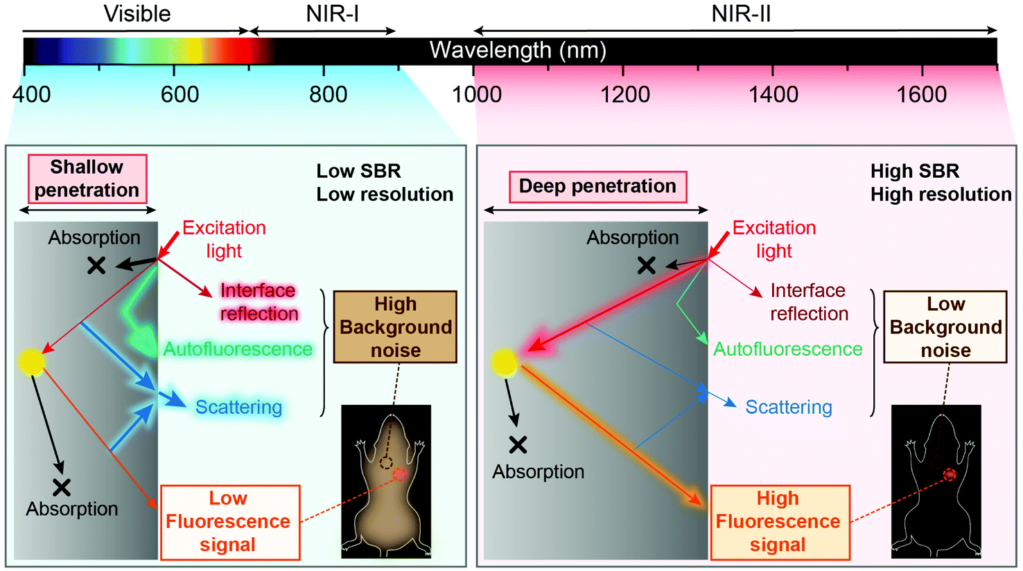 | ||
| Fig. 1 Comparison of bioimaging in the visible to NIR-I region and NIR-II region. | ||
Benefitting from the above merits of NIR II light, many activatable fluorescence sensors for bio-detection in the NIR-II region have been reported in the past decades to achieve higher detection sensitivity and imaging SBR.36–38 In a traditional bio-detection based on fluorescence sensing, regular responses in the spectral properties of fluorescence probes after interacting with analytes are necessarily required. Here, according to the regulated parameters of fluorescence emissions, the responses can be classified into three parts, including signal intensity variation, emission wavelength variation and fluorescence (or luminescence) lifetime variation of the sensing probes (Fig. 2). In this review article, we will summarize and discuss the sensors in the NIR-II region for bio-detection based on the above spectral variations. In addition, challenges and opportunities of NIR-II fluorescent probes for in vivo bio-detection with high accuracy and spatial resolution are discussed as well.
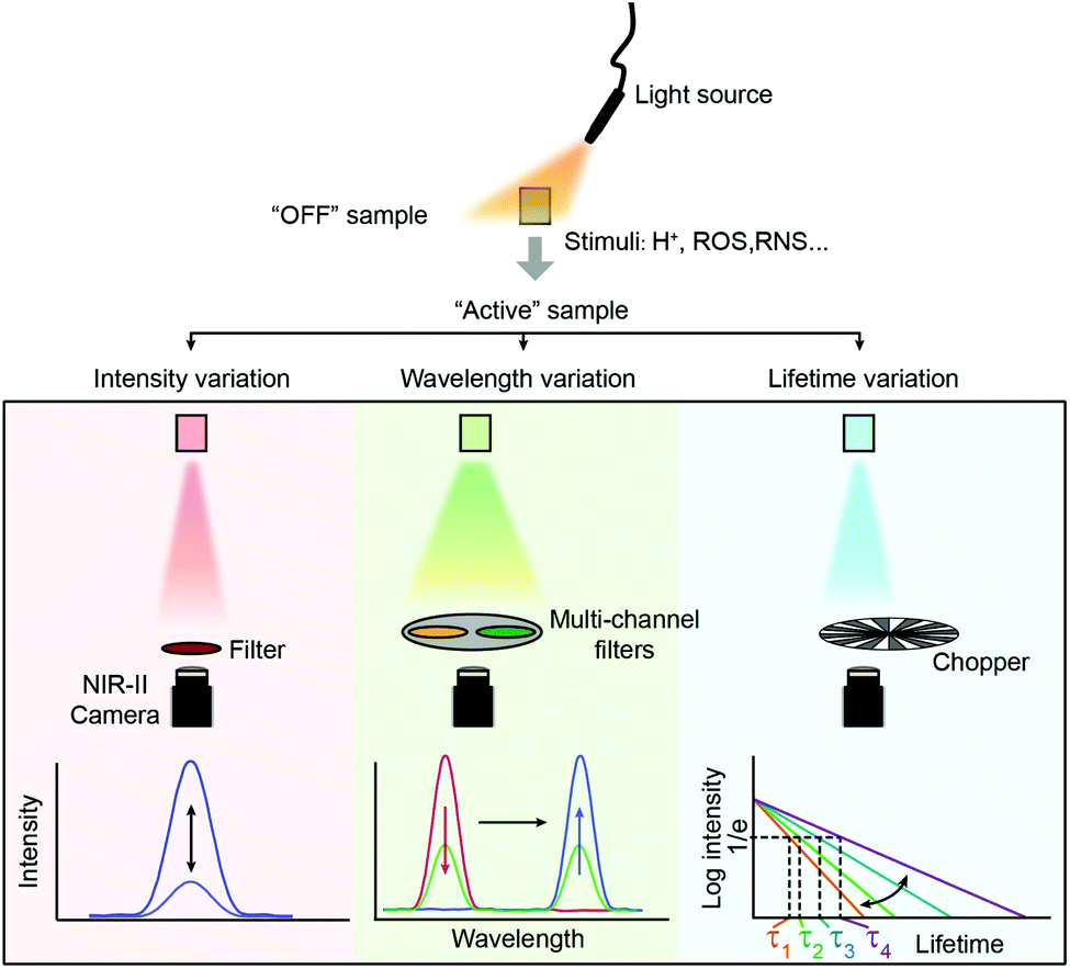 | ||
| Fig. 2 Spectral properties used in fluorescence sensing. From top to bottom, biosensing is performed using variations of signal intensity, wavelength and fluorescence lifetimes. | ||
2. Biosensing based on fluorescence signal intensity variation
So far, three types of NIR II fluorescent sensors to detect in vivo analytes based on fluorescence intensity variation have been developed: organic sensors, inorganic sensors and organic–inorganic hybrid sensors.2.1 Organic sensors
Detection pathways involving chemical reactions are the most common methods, owing to their high selectivity and sensitivity.1,42–44 Some pro-fluorescent dyes whose fluorescence can be unmasked only via chemical reactions have been elaborated for detection of physiological parameters or clinically relevant species.45,46Based on H2S-induced cleavage reaction of 4-nitrobenzenethiol groups, activatable NIR-II fluorescence sensor ZX-NIR was reported, in which boron-dipyrromethene hemicyanine was chosen as the NIR-II fluorescence reporter (Fig. 3a). With the addition of H2S, the NIR-II emission (900–1300 nm) of sensors was activated, achieving deep-tissue penetration and high SBR (5.7) imaging of human colorectal (HCT116) cancer (Fig. 3b–d).39 In 2019, Zhang and coworkers reported an ONOO−-activatable NIR-II fluorescence sensor IRBTP-B for drug-induced hepatotoxicity detection (Fig. 3e). The phenyl borate group as the common ONOO− response moiety was introduced into conjugated backbones to form IRBTP-B. In the presence of ONOO−, the responsive group was oxidized and further electron rearrangement occurred, generating NIR-II cyanine dye IRBTP-O and leading to an increase in emission intensity and a low detection limit (55.9 nM) (Fig. 3f). Utilizing the designed NIR-II fluorescent sensor, in vivo fluorescence detection of drug-induced hepatotoxicity was achieved with a high SBR (6.0) (Fig. 3f).40
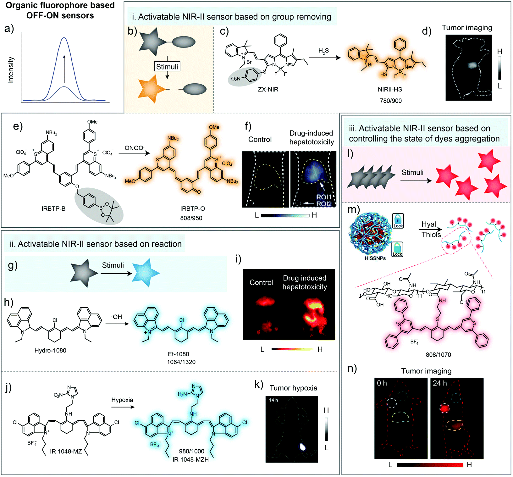 | ||
| Fig. 3 Organic fluorophore for biosensing in the NIR-II window. (a) Illustration of fluorescence spectral variation during organic fluorophore-based sensing. (b) Illustration of the NIR-II sensor based on group removing. (c) Chemical structure of the H2S-activatable NIR-II fluorescence sensor ZX-NIR and the sensing mechanism. (d) NIR-II imaging of human colorectal cancer with ZX-NIR administration. Reproduced from ref. 39 with permission from Wiley-VCH, Copyright 2018. (e) Chemical structure of the ONOO−-activatable NIR-II fluorescence sensor IRBTP-B and the sensing mechanism. (f) Images of mouse liver during PBS- or APAP-induced hepatotoxicity with IRBTP-B administration. Reproduced from ref. 40 with permission from American Chemical Society, Copyright 2019. Removed groups are indicated with gray circles. (g) Illustration of the NIR-II sensor based on reaction. (h) The chemical structure of the ·OH-activatable NIR-II fluorescence sensor Hydro-1080 and the sensing mechanism. (i) NIR-II imaging of drug-induced hepatotoxicity of mice with Hydro-1080 administration under 1064 nm excitation. Reproduced from ref. 36 with permission from American Chemical Society, Copyright 2019. (j) Chemical structure of the hypoxia-activatable NIR-II fluorescence sensor IR1048-MZ and the sensing mechanism. (k) NIR-II imaging of tumor hypoxia with IR1048-MZ administration. Reproduced from ref. 37 with permission from the Ivyspring International Publisher, Copyright 2018. (l) Illustration of the NIR-II sensor based on controlling the dye aggregation states. (m) Schematic of tumor-specific imaging nanoparticles (HISSNPs). (n) NIR-II imaging of tumors with HISSNP administration. Reproduced from ref. 41 with permission from Wiley-VCH, Copyright 2018. | ||
Besides group removing, some pro-fluorophores could also be activated by reacting with stimuli, forming an “on” state molecule for bio-sensing (Fig. 3g). Although the fluorescence band for in vivo imaging was adjusted into the NIR-II region by using a long-pass filter, the emission peaks of the cyanine dye NIRII-HS and IRBTP-O were not located in the NIR-II windows, eventually resulting in the loss of emission intensity due to the optical filters with long cut-off wavelength. So there still existed room to lengthen the emission wavelength. Liu and coworkers reported the ·OH-activatable NIR-II fluorescence sensor Hydro-1080 based on the reported NIR-II dye FD-1080 (Fig. 3h). Initially, the sensor Hydro-1080 consisted of two independent conjugated π systems, making the molecular structure non-fluorescent. After specifically oxidized by ·OH to conjugate the above two π systems, the new product Et-1080 with a longer conjugated π system would exhibit red-shifted fluorescence emission at 1080 nm. The low detection limit was reported to be 0.5 nM, which enabled the detection of physiological levels of ·OH. Then, the inflammatory liver model induced by APAP stimuli was successfully built for bioimaging (Fig. 3i).36 Meanwhile, Cai and coworkers have developed a hypoxia-activatable NIR-II fluorescence sensor IR1048-MZ through conjugating the nitroreductase (NTR) enzyme-responsive nitro imidazole group into commercial dye IR-1048 (Fig. 3j). After the hypoxia-activatable sensor IR1048-MZ was reduced to form amino imidazole by NTR, the intensity of emission at 1046 nm was enhanced 106.9-fold (quantum yields increased 300-fold from around 0.002% to 0.6%). NIR-II imaging of IR1048-MZ has shown precise visualization of A549 tumor with a tumor-to-background ratio as high as 30.0 (Fig. 3k).37
Except for molecular sensors, NIR-II organic dyes, especially cyanine dyes, tend to form aggregates due to π–π stacking and electrostatic interactions with other dye molecules.47,48 This may result in different optical profiles between monomers and aggregates. H-aggregates are considered to be head-to-head dipole arrangement, displaying blue-shifted absorption bands and weak fluorescence compared with monomers.33,49–52 Thus, controlling the aggregation behavior of dyes is also an optional method for developing sensors to detect physiological parameters or clinically relevant species(Fig. 3l).6,53–55 Fan and coworkers developed dual-pathological-parameter cooperatively activatable NIR-II sensors based on adjusting the IR-1061 aggregation state (Fig. 3m). In this system, commercial NIR-II dye IR-1061 was covalently attached to hydrophilic hyaluronic acid (HA), which could self-assemble to form nanoparticles. Then, disulfide was used to crosslink the HA to form the dual activatable sensor HISSNPs. The self-quenched NIR-II emission of IR-1061 could “turn-on” only in the presence of both overexpressed hyaluronidase and thiol due to the accompanied change from aggregates to monomers. The SBR of the fluorescent probe HISSNPs with high specificity imaging of tumors could reach 15.4 (Fig. 3n).41
2.2 Inorganic sensors
Inorganic nanoparticles are rarely applied individually as responsive sensors due to their relatively stable structures and spectral properties.57–60 Generally, to obtain the responsive signal change, the fluorescence or luminescence energy transfer pathway should be activated, interrupted or influenced (Fig. 4a). Thus, in inorganic nanostructures, reactive components such as ions are essential. In 2017, the cerium ion (Ce3+) was first introduced into the NaYbF4:Er3+ nanostructure to construct the Yb3+ → Er3+→ Ce3+ energy transfer pathway.56 Accelerating the non-radiative relaxation from state 4I11/2 to 4I13/2 (Er3+) through cross relaxation between Er3+ and Ce3+, the 4I13/2 level was impressively populated, resulting in the 9-fold enhancement of the downconversion luminescence at 1550 nm. On this basis, with the valence state changing ability of Ce3+/Ce4+, the NaCeF4:Er3+/Yb3+ sensor was fabricated by Chen and co-workers for uric acid (UA) detection using the signal intensity change at 1530 nm (Fig. 4b). In the presence of UA and uricase, the following reaction occurred: UA + uricase + H2O + O2 → allantoin + H2O2 + CO2. The generated H2O2 oxidized Ce3+ into Ce4+, leading to the declined energy transfer efficiency and decreased luminescence intensity at 1530 nm (Fig. 4c and d). Through the simple mix-and-measure type assay, the low limit of detection (LOD) down to 25.6 nM allowed the sensitive detection of UA in human serum. Moreover, the deep-tissue penetration up to 10 mm beyond 1500 nm offered the in vivo detection potential for the NaCeF4:Er3+/Yb3+ sensor. This Ce3+/Ce4+ based inorganic sensor could be further applied in the H2O2 and other bio-reactive species related reactions for bio-marker sensing.56 Inspired by the achievement, other metal ions with responsive valence states, such as Fe2+ and Mn3+, might also allow the all-inorganic activatable fluorescence detection through incorporating them into lanthanide-doped nanocrystals or quantum dots. This is also an important research direction for broadening the in vivo quantitative detection of pure inorganic fluorescent probes.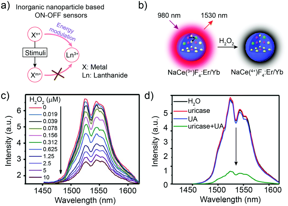 | ||
| Fig. 4 Inorganic nanoparticles for biosensing in the NIR-II window. (a) Schematic illustration of inorganic nanoparticle-based sensing. (b) Schematic illustration of NaCeF4:Er,Yb nanoparticles for H2O2 biosensing. (c) NIR-II luminescence emission response of the NaCeF4:Er,Yb sensor with the addition of H2O2. Ex: 980 nm. (d) NIR-II luminescence spectra of the NaCeF4:Er,Yb sensor after the addition of H2O, uricase, UA, and uricase + UA, respectively. Reproduced from ref. 56 with permission from the Royal Society of Chemistry, Copyright 2018. | ||
2.3 Organic–inorganic composites
As mentioned in Section 2.2, most inorganic nanoparticles, including quantum dots (QDs) and lanthanide-doped nanoparticles, are hardly individually used for bio-sensing due to their non-responsive property.57,63–66 Nevertheless, their robust spectral properties provide them an opportunity as the stable donors in energy transfer systems or the calibrated reference signal in ratiometric fluorescent/luminescent imaging systems.67,68 In contrast, organic dyes with relatively weak chemical and structural stabilities are suitable to serve as responsive detection signals, respectively.69 Based on a FRET system consisting of the Ag2S and ONOO− sensitive chromophore A1094, Wang and coworkers realized the real-time detection of vascular inflammation caused by traumatic brain injury (Fig. 5a). After reacting with ONOO− in the inflamed area, the FRET process was interrupted along with A1094 destruction. Thus, the responsive and targeted V&A@Ag2S sensor was activated from the “off” state to the “on” state, emitting a bright fluorescence sensing signal with a high SBR (>10.2) beyond 1000 nm. With an LOD down to 60 nM, vascular inflammation was rapidly detected in 5 min after V&A@Ag2S administration compared to the “always on” V@Ag2S and non-targeted A@Ag2S control groups (Fig. 5b and c).38 Similarly, Ag2S and A1094 were further used in another FRET system. Under coordination and electrostatic interaction between Fmoc-His, Er3+, Ag2S, A1094 and chemodrug doxorubicin (DOX), the five components spontaneously self-assembled into the activatable sensor Fmoc-His/Er3+/Ag2S/DOX/A1094 (FEAD1) with a quenching efficiency of 82%.70 Triggered by the acidic tumor micro-environment (pH 5.5), disassembly occurred and the FRET process between Ag2S and A1094 was cut off, resulting in the fluorescence recovery of Ag2S around 1200 nm. Metastatic nodules in a tumor-bearing mouse model could be precisely profiled and excised under the guidance of “on” state NIR-II imaging with an SBR of 7.0. Meanwhile, the released DOX provided chemotherapy effects for this nanotheranostic system.70 Except for FRET, photoinduced electron transfer (PET) could also be used for fluorescence quenching.71–75 Kim and co-workers selected methylene blue as the PET quencher to suppress the fluorescence of PbS/CdS/ZnS QDs through a protease-cleavable peptide sequence. This sensor demonstrated in vitro selective fluorescence activation at colon tumor sites with 3-fold signal enhancement in 10 min after spray.76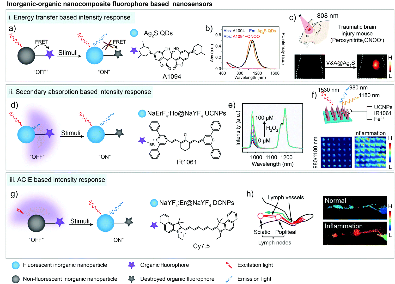 | ||
| Fig. 5 Organic–inorganic nanocomposites for bio-sensing through energy transfer, secondary absorption and ACIE-based signal intensity response in the NIR-II window. (a) Schematic of the energy transfer based organic–inorganic nanocomposite for bio-sensing. (b) ONOO− response spectra of A1094 dye. (c) NIR-II bioimaging of the TBI model after V&A@Ag2S sensor administration. Reproduced from ref. 38 with permission from Wiley-VCH, Copyright 2019. (d) Schematic of the secondary absorption based organic–inorganic nanocomposite for bio-sensing. (e) NIR-II luminescence emission response of the sensor in the presence of H2O2. (f) Ratiometric (blue I980/I1180) images of microneedle patches before and after acute inflammation. Reproduced from ref. 61 with permission from Wiley-VCH, Copyright 2018. (g) Schematic of the ACIE based organic–inorganic nanocomposite for bio-sensing. (h) Anatomical structure of the mouse lymphatic system and the ratiometric luminescent imaging of healthy and inflamed mouse lymphatic systems. Reproduced from ref. 62 with permission from American Chemical Society, Copyright 2019. | ||
In other cases, the distance between inorganic nanoparticles and organic dyes is not close enough for energy transfer. However, the organic dyes could serve as photon filtration layers and absorb the fluorescence (or luminescence) emission of the inorganic nanoparticles, which is known as secondary absorption, also leading to the signal decrease of the sensor.77 For instance, Er3+ sensitized upconversion nanoparticles NaErF4:Ho3+@NaYF4 with 1530 nm excitation and 980/1180 nm emission were fabricated by Zhang and co-workers. Then the sensing organic dye IR1061 and Fenton catalyst Fe2+ were co-encapsulated with NaErF4:Ho3+@NaYF4 nanoparticles in the microneedle patch for in vivo inflammation detection (Fig. 5d). In the presence of H2O2, IR1061 degraded and lost the absorption ability at 980 nm, causing the significant intensity recovery of 980 nm upconversion emission (Fig. 5e). Meanwhile, another upconversion emission at 1180 nm was not influenced by the IR1061 sensing dye, which could be used as a stable reference signal in ratiometric luminescent imaging. The ratiometric signal change from single needles could be easily distinguished with high resolution (200 μm × 200 μm) for H2O2 quantitative evaluation owing to the low auto-fluorescence and tissue scattering (Fig. 5f).61
In addition, organic dyes with a high extinction coefficient (usually thousand-fold higher than that of lanthanide ions) could not only absorb the emission light of fluorescent (or luminescent) nanomaterials, but also absorb the excitation light. Thus, high absorption coefficient organic dyes and low absorption coefficient inorganic nanoparticles form an absorption competition-induced emission (ACIE) system. In 2017, Zhang and co-workers first reported a Nd3+-NPTAT ACIE system for an oral drug delivery monitor.77 Based on this, they further used Cy7.5 with maximum absorption around 800 nm as a competition dye to construct the ACIE process between Cy7.5 and Er3+ doped downconversion nanoparticles for in vivo HClO detection in the NIR-II window.62 1550 nm emission under 980 nm laser excitation was selected as a self-calibrated reference signal and 1550 nm emission under 808 nm laser excitation was chose as a sensing signal (Fig. 5g). After reacting with HClO, destructed Cy7.5 lost the filtration function under 808 nm laser excitation, leading to the signal recovery at the 808 nm excitation channel. This ratiometric sensing system displayed fast and good linear ratiometric fluorescent response to HClO at 1550 nm under dual-wavelength excitation with a detection limit down to 500 nM. Signal collection beyond 1500 nm also decreased the imaging background noise, providing a higher resolution, SBR (8.9) and sensitivity in ratiometric biosensing in inflammatory lymphatic systems (Fig. 5h).62
3. Biosensing based on wavelength variation
Wavelength-variation based ratiometric imaging is another method for in vivo analyte sensing. Different from the demonstrations in Section 2.3, wavelength-variation based ratiometric imaging does not need an unchanged reference signal and the emission spectral shapes of sensors will be affected by responding to analytes. Resonance energy transfer is a common and valuable mechanism for building wavelength-ratiometric sensors. In FRET systems, if both donor and acceptor exhibit detectable emissions, any process that influences the molecular structure or distance between the donor and acceptor will cause a change in central wavelengths of emissions (Fig. 6a). In 2019, Zhang and coworkers reported a new series of NIR-II CX dyes via hybridization of rhodamine and cyanine dye structures.78 An ONOO−-activatable NIR-II fluorescence sensor PN1100 was constructed by encapsulating CX-1 and CX-3 into micelles based on a resonance energy transfer mechanism (Fig. 6b). The fluorescent sensor exhibited a weak fluorescence peak of CX-1 at 920 nm and a relatively strong emission peak of CX-3 at 1130 nm. After adding ONOO− into the micelle sensing system, CX-3 was gradually oxidized. The emission peak at 920 nm was increased continuously, accompanied by a monotonous decrease of the emission peak at 1130 nm (Fig. 6c). The in vivo ratiometric imaging clearly indicated that ONOO− was generated in the liver area of APAP-treated mice, showing great potential of the NIR-II fluorescence sensor PN1100 for in vivo bio-detection (Fig. 6d).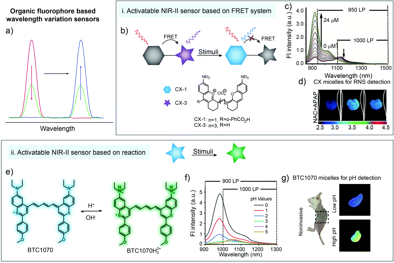 | ||
| Fig. 6 (a) Illustration of organic fluorophore based wavelength variation for bio-sensing. (b) Schematic of wavelength variation based on a FRET system and the chemical structures of CX-1 and CX-3. (c) The emission spectra of the sensor (CX micelles) upon addition of ONOO−. (d) Ratiometric imaging of a liver during APAP-induced hepatotoxicity with CX micelle administration. Reproduced from ref. 78 with permission from Wiley-VCH, Copyright 2019. (e) Chemical structure of the pH-activatable NIR-II fluorescence sensor BTC1070 and the sensing mechanism. (f) The emission spectra of the sensor (BTC1070) at different pH values. (g) Ratiometric imaging of gastric pH with BTC1070 micelle administration. Reproduced from ref. 79 with permission from Springer Nature, Copyright 2019. | ||
Besides FRET systems, spectral shape variation also occurs in some molecules after responding to stimulus. For instance, Zhang and coworkers reported a pH-activatable NIR-II fluorescence sensor BTC1070 through modification of commercial dye IR-26 (Fig. 6e). The nitrogen atom at terminal groups could be protonated under acidic conditions, which exhibited ratiometric emission change from 1065 to 980 nm when pH changed from 5 to 0 (Fig. 6f). The in vivo experimental results demonstrated the ability for noninvasive ratiometric quantification of gastric pH under a tissue depth of 4 mm (Fig. 6g), unlocking the potential of BTC1070 sensors for NIR-II bio detection.79
During detection, wavelength variation could also be regarded as the signal intensity variation in specific signal collection windows. In general, a biosensor based on wavelength variation mainly shows increased and decreased intensities of different emission peaks. For instance, in Fig. 6c, the fluorescence intensity at 950–1500 nm could be collected from two wavelength windows. One is the signal increasing window in the whole wavelength range, and another is the signal decreasing window in the 1000–1500 nm region. Compared to the fluorescence imaging based on emission intensity, ratiometric fluorescence imaging could further magnify the signal variation after responding to stimuli, providing higher detection sensitivity.
4. Biosensing based on luminescence lifetime variation
Due to the tissue scattering and absorption of excitation and emission light, inhomogeneous and unavoidable signal intensity attenuation occurs during luminescence bioimaging and biosensing, even in the NIR-II window, leading to the major challenge for quantitative biosensing.81,82 Although to some extent, ratiometric fluorescence (and luminescence) imaging has obtained the calibrated signal for quantitative biosensing despite tissue penetration depth, the extra introduced calibration signal would still cause the heavier workload.As the intrinsic property of fluorescent (and luminescent) materials, fluorescence lifetime exhibits robust values regardless of probe concentration and tissue penetration depth.83–85 Up to now, lanthanide-doped nanoparticles with a Nd3+ sensitizer, Yb3+ energy transmitter, and Er3+/Ho3+ emitter have been fabricated as NIR-II lifetime contrast agents (emission peaks at 1525 nm and 1155 nm, respectively). Lifetime values could be resolved under 8 mm tissue penetration, and breast tumor subtypes in living mice were identified through in vivo multiplexing.86 However, the series lifetime values were obtained by regulating the thickness of the energy relay layer, which was still not activatable.
To obtain the response ability, a FRET nanocomposite consisting lanthanide nanoparticles and cyanine dye was constructed by Zhang and coworkers for luminescence lifetime imaging based tumor detection.80 Nd3+ doped nanoparticles NaYF4@NaYF4:1%Nd (DSNP) with emission of 1060 nm were chosen as the FRET donor, and specifically designed dye MY-1057 with NIR-II absorption was selected as the FRET acceptor (Fig. 7a). The luminescence lifetime of the sensor (DSNP@MY-1057-GPC-3) was determined using the amount of surface modified MY-1057. Thus, in the presence of peroxynitrite (ONOO−), a kind of excess reactive nitrogen species (RNS) at the tumor micro-environment, the chemical structure of MY-1057 would be degraded, leading to the luminescence lifetime recovery from 203 ± 2 μs to 298 ± 2 μs at 1060 nm (Fig. 7b). Through NIR-II lifetime imaging, multi hepatocellular carcinoma (HCC) lesions with recovered lifetimes from 215 ± 27 μs to 249 ± 43 μs could be precisely distinguished from healthy hepatic tissue with a lifetime of 204 ± 10 μs. The lifetime detection results were in agreement with MRI and dissected results, suggesting the accuracy and reliability of lifetime imaging. Most importantly, the lifetime recovery function under various penetration depths stayed consistent, which could not be achieved by fluorescence intensity imaging, illustrating the quantification ability of lifetime imaging based detection (Fig. 7c and d).80
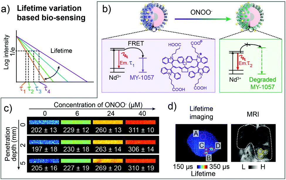 | ||
| Fig. 7 Luminescence lifetime FRET sensor for ONOO− response and HCC detection in the NIR-II window. (a) Schematic of responsive and distinguishable fluorescence lifetime (τ1, τ2, τ3, τ4) for fluorescence lifetime imaging. (b) Design of FRET sensor based on DSNP@MY-1057-GPC-3 compound for ONOO− detection. (c) NIR-II lifetime imaging DSNP@MY-1057-GPC-3 sensor at various penetration depths before and after responding to ONOO−. (d) Noninvasive NIR-II lifetime imaging and MRI of a mouse liver with three HCC lesions. ROI A: healthy hepatic tissue; ROI B–D: tumor lesions distinguished from lifetime imaging. Reproduced from ref. 80 with permission from Wiley-VCH, Copyright 2020. | ||
Thanks to the high stability and reliability, fluorescence lifetime imaging provides researchers a potential and powerful tool for qualitative and quantitative imaging and detection of reactive bio-analytes.84,86–88 Technically, the pulsed excitation and temporal domain used during fluorescence lifetime imaging remove the auto-fluorescence noise, giving a non-background imaging result, which extremely increases the detection sensitivity.89–91 The pulsed excitation also avoids the thermal effects to a large extent, offering the opportunity for higher laser power density during imaging. Promisingly, with the deep penetration of NIR-II imaging and reliability of lifetime imaging, activatable NIR-II lifetime imaging would further broaden the in vivo and in situ detection and sensing.
5. Summary, challenges and outlook
In this minireview, we have summarized and discussed the recently developed activatable NIR-II fluorescence sensors for bio-sensing and bio-detection (Table 1). These sensors could be mainly divided into three kinds by the substantial signal variation type: variation of signal intensity, variation of signal wavelength and variation of fluorescence (or luminescence) lifetime. Among them, the most direct and commonly used sensing method is to change the fluorescence signal intensity of the sensor after interacting with analytes. For organic dyes, designing of responsive chemical structures is an effectual method to obtain molecular sensors. Moreover, combining non-responsive dyes and a responsive polymer matrix is another efficient way to obtain sensing signal without heavy molecular design and synthesis work. Furthermore, to construct the signal intensity sensing systems, energy transfer (including FRET and PET), secondary absorption and ACIE processes have been utilized by using organic dyes and inorganic nanoparticles. After responding to analytes, these processes would be interrupted or influenced, leading to the signal intensity variation. Signal wavelength is another important property of fluorescence sensors. The relative shift of the emission peak would also result in the signal intensity change in a narrow imaging channel. Based on the signal intensity change at metabolic emission bands, wavelength-variation based ratiometric fluorescence imaging is proposed. The advantage is that the ratiometric imaging can alleviate the influence of light scattering and absorption caused by bio-tissues to a large extent, vigorously promoting the in vivo quantitative sensing ability. In addition, due to the lack of background noise and the tissue thermal effect, fluorescence lifetime based sensing provides another opportunity for quantitative sensing without using any extra reference signal due to the stable and robust lifetime value under tissue penetration.| Signal variation | Sensor | Designed mechanism | Stimulant | Ex (nm) | Em (nm) | SBR | LOD (nM) | Ref. |
|---|---|---|---|---|---|---|---|---|
| Intensity | Boron-dipyrromethene (ZX-NIR) and aza-BODIPY nanocomposites | Target-induced group removal of fluorophores | H2S | 780 | 900 | 5.7 | 37 | 39 |
| Cyanine dye IRBTP | Target-induced group removal of fluorophores | ONOO− | 808 | 950 | 6 | 55.9 | 40 | |
| Cyanine dye IR 1048-MZ | Reaction with the target | Hypoxia | 980 | 1000 | 30 | — | 37 | |
| Cyanine dye Hydro-1080 | Reaction with the target | ·OH | 1064 | 1320 | 6 | 0.5 | 36 | |
| IR-1061 modified polymeric HISSNPs | Target-induced dye aggregation state change | GSH and hyaluronidase | 808 | 1070 | 15.4 | — | 41 | |
| NaCeF4:Er,Yb | Target-induced change of ion valence | H2O2 | 980 | 1530 | — | 41.8 | 56 | |
| NaErF4:Ho@NaYF4 UCNPs, IR-1061 and Fe2+ nanocomposites | Target caused destruction of secondary absorption cyanine dye | H2O2 | 1530 | 980 | — | — | 61 | |
| Ag2S and croconium dye A1094 nanocomposites V&A@Ag2S | Target caused destruction of a FRET acceptor dye | ONOO− | 808 | 1050 | 10.2 | 60 | 38 | |
| Fmoc-His, Ag2S, DOX and croconium dye A1094 nano-assembly | Target-induced disassembly | H+ | 808 | 1200 | 7 | — | 70 | |
| PbS/CdS/ZnS and MB nanocomposites | Target-induced linker cleavage of a PET donor and acceptor | MMP | 910 | 1200 | — | — | 76 | |
| NaYF4:Er@NaYF4 UCNPs and Cy7.5 nanocomposites | Target caused destruction of a filtration dye | HClO | 808/980 | 1550 | 38 | 500 | 62 | |
| Wavelength | Cyanine dye CX-1 and CX-3 nanocomposites | Target caused destruction of a FRET acceptor dye | ONOO | 808 | 1000–1700 | 17.4 | — | 78 |
| Cyanine dye BTC1070 | Reaction with the target | PH | 808 | 1000 | — | — | 79 | |
| Lifetime | NaYF4@NaYF4:Nd DSNPs and cyanine dye MY-1057 nanocomposites | Target caused destruction of a FRET acceptor dye | ONOO− | 808 | 1060 | — | — | 80 |
Although promising, in vivo sensing and detection in the NIR-II window still faces great challenges. From the design of materials to the application in vivo, here are several ideas proposed to improve the sensing reliability and sensitivity.
(i) The basic method to improve sensing sensitivity is to improve the brightness and photostability of contrast agents. Higher signal intensity brings less administration dosage and lower biotoxicity. With enough NIR-II brightness, the SBR and resolution of bioimaging would be largely promoted. Unfortunately, most of the previously reported NIR-II contrast agents usually exhibit unsatisfactory brightness. For instance, although having high extinction coefficients, most organic dyes with long excitation/emission wavelengths in the NIR region show extremely low quantum yield, leading to low brightness. Despite being the most widely used inorganic materials, rare-earth doped nanoparticles often suffer from a low extinction coefficient. To improve the brightness of NIR-II probes, various efforts have been made so far. For organic molecular contrast agents, enhancing the rigidity of the π-conjugated systems and avoiding heavy metal elements are the two main methods to improve brightness.92,93 As for inorganic rare-earth materials, structural design including element doping to populate the emitting level and introducing a shell structure into nanoparticles to decrease lattice imperfection have been reported to obtain higher brightness. Besides, lanthanide luminescence sensitized by organic dyes that have a high extinction coefficient could also enhance the brightness through improving the absorption cross-section.
Apart from emphasizing the brightness improvement of NIR-II emitting materials through structure design, researchers should also pay attention to the fluorescence quenching and photo- and chemo-stability of the contrast agents after being administered in vivo. Encapsulating into a polymer matrix and binding with proteins have been widely used to resist fluorescence quenching and enhance the stability of organic molecular dyes. As for inorganic nanoparticles, shell protection could remarkably strengthen the anti-quenching ability and surface modification such as the cross-link-function could improve the stability in a complex physiological environment.94
(ii) Intensity-based bio-imaging and bio-sensing only have the ability of qualitative detection in vivo. It is unreliable to use intensity changes to measure the concentration of analytes in the presence of tissue penetration, which is due to a wide variety of reasons. Due to the photobleaching and diffusion of fluorescence sensors, the collected signal fails to represent the true sensing signal. Meanwhile, various types of bio-tissues can affect the light emitted from the sensor due to tissue scattering and absorption. Thus, to promote quantitative reliability, reference materials or reference signals could be introduced to combine with the signal intensity change for bio-sensing.
(iii) Different from fluorescence intensity, fluorescence lifetime of lanthanide ions is independent of excitation energy, particle concentration, tissue depth, photon scattering and the microenvironment. Hence, in vivo bio-detection based on fluorescence lifetime imaging will provide accurate and quantitative results. However, the progress of fluorescence lifetime imaging for in vivo quantitative bio-detection is slow and unsatisfactory, mainly resulting from the difficulty in designing effective nano-compositions that are responsive and activatable under some stimuli. To be specific, the present biosensors based on variational fluorescence lifetimes mainly contain molecular sensors, coordination compounds and FRET nano-composites. Unfortunately, few NIR-II responsive molecules or coordination compounds have been reported due to the difficulty in chemical synthesis and the limited detection range of fluorescence lifetime imaging systems. As for FRET nano-composites for wide-field NIR-II fluorescence lifetime imaging based on InGaAs detectors, rare-earth doped nanoparticles and lanthanide complexes with a typical long fluorescence lifetime ranging from microseconds to milliseconds are more suitable than QDs that show a shorter fluorescence lifetime (∼ns). However, sensitivities of these FRET nano-composites are unable to satisfy the detection requirement because a relatively small change of fluorescence lifetime cannot be well identified in the reported wide-field NIR-II fluorescence lifetime imaging system. In addition, difficulties in the synthesis of NIR-II responsive energy acceptors also hinder the development of lifetime sensors. To solve the bottleneck issues, fluorescent materials with high sensitivity for bioassays should be developed and reconstructed to serve as novel fluorescence lifetime energy donors. On the other hand, the widely used signal intensity changing systems are often based on the energy transfer process, which would also lead to the fluorescence (or luminescence) lifetime change. Thus, the signal intensity changing systems caused by energy transfer could also be used as lifetime changing systems for reliable quantitative bio-sensing. Besides, as mentioned in the “Biosensing based on wavelength variation” section, wavelength variation could also be regarded as the signal intensity variation in specific signal collection windows. Therefore, the molecules with tunable wavelength upon external stimulus could also be used as energy acceptors in FRET systems to influence the fluorescence lifetime of energy donors with corresponding fluorescence emissions.
(iv) Tissue scattering, absorption and auto-fluorescence are largely dependent on the light wavelength. Thus, during ratiometric fluorescence imaging, fluorescence signals in various collection channels exhibit different degrees of attenuation in the presence of tissue penetration, which would cause the deviation in fluorescence ratio and decrease the sensing reliability. To solve the problem, adjacent and partially overlapped wavelength regions with similar signal attenuation coefficients in tissue could be selected to maximally reduce the influence of tissue scattering, absorption and auto-fluorescence. For instance, Er3+ doped particles with emission at 1525 nm and PbS quantum dots with emission around 1500 nm could be used for ratiometric fluorescence imaging due to the overlapped emission wavelength. On this basis, quantitative bio-detection would be achieved with higher sensing reliability.
(v) Delivery pathways, including intravenous injection, intraperitoneal injection, spraying, microneedle patches and oral delivery, also have important influence on delivery efficiency and bio-sensing sensitivity in different animal models. For example, the intravenous injection delivery pathway for a peritoneal metastasis tumor model often shows low accumulation ability while intraperitoneal injection could largely improve the accumulation. Spraying methods exhibit high convenience during imaging-guided laparotomy operation. Microneedle patches are more suitable to apply to skin or shallow tissue related diseases, and oral delivery is adaptable for gastrointestinal imaging and sensing. Thus, a suitable delivery pathway should be selected according to different diseases to obtain higher sensitivity.
(vi) Improvements in in vivo optical imaging systems are also desired in NIR-II sensing. A compatible NIR II optical imaging system with satisfactory sensitivity will provide better detection efficiency. However, for a flexible refit and specific demand of detection purpose, most of the NIR II imaging systems are now home-built, resulting in the problem of complicated operation. Simply, a conventional NIR II imaging system mainly consists of an InGaAs detector, a camera lens and filters. Several factors, including the transmittance of these optical components in the NIR II range, the collection efficiency of fluorescence, the dark current of the NIR II detector, the performance of the camera lens and the optical density (OD) values of the optical filters, will undoubtedly determine the sensitivity of the whole imaging system. In order to realize superior sensitivity, all of the above optical parameters should be optimized. For example, higher fluorescence transmittance and OD values, and lower dark current will provide a strong fluorescence intensity and low background, thus ensuring a higher SBR.
Compared to the fluorescence intensity imaging, fluorescence lifetime imaging can provide both qualitative and quantitative results. Therefore, an NIR II fluorescence lifetime imaging system is a highly necessary instrument for in vivo quantitative detection. The present system is based on an optical chopper and a data acquisition card (DAQ) to control time synchronization. However, due to the limit of the rotation speed of the optical chopper and the long response time of lasers through transistor–transistor logic (TTL) modulation, the fluorescence lifetime threshold is larger than 50 μs up to now. An alternative method based on a ns (10−9 s) pulsed laser for synchronization control to achieve accurate detection of shorter fluorescence lifetime is highly required. Besides, the use of an optical chopper will introduce more than two pieces of achromatic lens, which will bring about the reduced transmittance of fluorescence and decreased spatial resolution. More efficient design for optimizing the optical system is still on the way.
Conflicts of interest
The authors declare no conflict of interest.Acknowledgements
The work was supported by the National Key R&D Program of China (2017YFA0207303), National Natural Science Foundation of China (NSFC, 21725502 and 51961145403), Shanghai Sailing Program (20YF1402200), and Key Basic Research Program of Science and Technology Commission of Shanghai Municipality (17JC1400100, 19490713100 and 20490710600).Notes and references
- W. Sun, S. Guo, C. Hu, J. Fan and X. Peng, Chem. Rev., 2016, 116, 7768–7817 CrossRef.
- J. Li and K. Pu, Chem. Soc. Rev., 2019, 48, 38–71 RSC.
- M. Yang, J. Fan, J. Du and X. Peng, Chem. Sci., 2020, 11, 5127–5141 RSC.
- Y. Xu, B. Li, P. Han, S. Sun and Y. Pang, Analyst, 2013, 138, 1004–1007 RSC.
- O. S. Wolfbeis, Anal. Chem., 2004, 76, 3269–3284 CrossRef.
- B. Li, W. Li, Y. Xu, J. Li, J. Tu and S. Sun, Chem. Commun., 2015, 51, 14652–14655 RSC.
- A. K. East, M. Y. Lucero and J. Chan, Chem. Sci., 2020 10.1039/d0sc03096a.
- B. H. Li, Y. L. Zhang, F. S. Li, W. Wang, J. Liu, M. Liu, Y. Cui, X. B. Li and B. L. Li, Sens. Actuators, B, 2016, 233, 479–485 CrossRef CAS.
- Y. Tang, F. Pei, X. Lu, Q. Fan and W. Huang, Adv. Opt. Mater., 2019, 7, 1900917 CrossRef CAS.
- R. Richards-Kortum and E. Sevick-Muraca, Annu. Rev. Phys. Chem., 1996, 47, 555–606 CrossRef CAS.
- M. Zhao, R. Wang, B. Li, Y. Fan, Y. Wu, X. Zhu and F. Zhang, Angew. Chem., Int. Ed., 2019, 58, 2050–2054 CrossRef CAS.
- M. Zhao, B. Li, Y. Fan and F. Zhang, Adv. Opt. Mater., 2019, 8, 1801650 Search PubMed.
- G. Hong, A. L. Antaris and H. Dai, Nat. Biomed. Eng., 2017, 1, 0010 CrossRef CAS.
- B. Li, M. Zhao, L. Feng, C. Dou, S. Ding, G. Zhou, L. Lu, H. Zhang, F. Chen, X. Li, G. Li, S. Zhao, C. Jiang, Y. Wang, D. Zhao, Y. Cheng and F. Zhang, Nat. Commun., 2020, 11, 3102 CrossRef CAS.
- A. L. Antaris, H. Chen, Y. Sun, C. Qu, Z. Deng, X. Hu, X. Hong, A. L. Antaris, G. Hong, S. Diao, B. Zhang, X. Zhang, O. K. Yaghi, Z. R. Alamparambil, H. Dai, H. Chen, K. Cheng and Z. Cheng, Nat. Mater., 2016, 15, 235–242 CrossRef CAS.
- J. A. Carr, D. Franke, J. R. Caram, C. F. Perkinson, M. Saif, M. G. Bawendi, O. T. Bruns, V. Askoxylakis, M. Datta, D. Fukumura, R. K. Jain and M. Datta, Proc. Natl. Acad. Sci. U. S. A., 2018, 115, 4465–4470 CrossRef CAS.
- B. Li, L. Lu, M. Zhao, Z. Lei and F. Zhang, Angew. Chem., Int. Ed., 2018, 57, 7483–7487 CrossRef CAS.
- B. Ding, Y. Xiao, H. Zhou, X. Zhang, C. Qu, F. Xu, Z. Deng, Z. Cheng and X. Hong, J. Med. Chem., 2018, 62, 2049–2059 CrossRef.
- M. Zhao, B. Li, P. Wang, L. Lu, Z. Zhang, L. Liu, S. Wang, D. Li, R. Wang and F. Zhang, Adv. Mater., 2018, 30, 1804982 CrossRef.
- Y. Li, Z. Cai, S. Liu, H. Zhang, S. T. H. Wong, J. W. Y. Lam, R. T. K. Kwok, J. Qian and B. Z. Tang, Nat. Commun., 2020, 11, 1255 CrossRef CAS.
- J. Lin, X. Zeng, Y. Xiao, L. Tang, J. Nong, Y. Liu, H. Zhou, B. Ding, F. Xu, H. Tong, Z. Deng and X. Hong, Chem. Sci., 2019, 10, 1219–1226 RSC.
- F. Ding, Y. Zhan, X. Lu and Y. Sun, Chem. Sci., 2018, 9, 4370–4380 RSC.
- A. M. Smith, M. C. Mancini and S. Nie, Nat. Nanotechnol., 2009, 4, 710–711 CrossRef.
- Y. Sun, M. Ding, X. Zeng, Y. Xiao, H. Wu, H. Zhou, B. Ding, C. Qu, W. Hou, A. G. A. Er-bu, Y. Zhang, Z. Cheng and X. Hong, Chem. Sci., 2017, 8, 3489–3493 RSC.
- Y. Sun, F. Ding, Z. Chen, R. Zhang, C. Li, Y. Xu, Y. Zhang, R. Ni, X. Li, G. Yang, Y. Sun and P. J. Stang, Proc. Natl. Acad. Sci. U. S. A., 2019, 116, 16729–16735 CrossRef.
- Y. Sun, C. Qu, H. Chen, M. He, C. Tang, K. Shou, S. Hong, M. Yang, Y. Jiang, B. Ding, Y. Xiao, L. Xing, X. Hong and Z. Cheng, Chem. Sci., 2016, 7, 6203–6207 RSC.
- Y. Zhang, G. Hong, Y. Zhang, G. Chen, F. Li, H. Dai and Q. Wang, ACS Nano, 2012, 6, 3695–3702 CrossRef.
- B. Li, M. Zhao and F. Zhang, ACS Mater. Lett., 2020, 2, 905–917 CrossRef CAS.
- H. Zhang, Y. Fan, P. Pei, C. Sun, L. Lu and F. Zhang, Angew. Chem., Int. Ed., 2019, 58, 10153–10157 CrossRef CAS.
- T. Li, C. Li, Z. Ruan, P. Xu, X. Yang, P. Yuan, Q. Wang and L. Yan, ACS Nano, 2019, 13, 3691–3702 CrossRef CAS.
- S. Liu, C. Chen, Y. Li, H. Zhang, J. Liu, R. Wang, S. T. H. Wong, J. W. Y. Lam, D. Ding and B. Z. Tang, Adv. Funct. Mater., 2020, 30, 1908125 CrossRef CAS.
- R. Tian, S. Zhu, J. Lau, S. Chandra, G. Niu, D. O. Kiesewetter, X. Chen, Q. Zeng, B. R. Brooks, R. Ertsey, K. S. Hettie, T. Teraphongphom, Z. Hu, H. Sun, X. Zhang, A. L. Antaris, B. R. Brooks and X. Chen, Sci. Adv., 2019, 5, eaaw067 Search PubMed.
- C. Sun, B. Li, M. Zhao, S. Wang, Z. Lei, L. Lu, H. Zhang, L. Feng, C. Dou, D. Yin, H. Xu, Y. Cheng and F. Zhang, J. Am. Chem. Soc., 2019, 141, 19221–19225 CrossRef CAS.
- S. Diao, G. Hong, A. L. Antaris, J. Z. Wu, B. Zhang, H. Dai, J. L. Blackburn, J. Chang, C. J. Kuo and K. Cheng, Angew. Chem., Int. Ed., 2015, 54, 14758–14762 CrossRef CAS.
- Z. Ma, M. Zhang, J. Yue, Y. Zhong, H. Dai, C. Alcazar, T. C. Doyle and N. F. Huang, Adv. Funct. Mater., 2018, 28, 1803417 CrossRef.
- W. Feng, Y. Zhang, Z. Li, S. Zhai, W. Lv and Z. Liu, Anal. Chem., 2019, 91, 15757–15762 CrossRef.
- X. Meng, J. Zhang, Z. Sun, L. Zhou, G. Deng, S. Li, W. Li, P. Gong and L. Cai, Theranostics, 2018, 8, 6025 CrossRef.
- C. Li, W. Li, H. Liu, Y. Zhang, G. Chen, Z. Li and Q. Wang, Angew. Chem., Int. Ed., 2020, 59, 247–252 CrossRef.
- G. Xu, Q. Yan, X. Lv, Y. Zhu, K. Xin, B. Shi, R. Wang, J. Chen, W. Gao, P. Shi, C. Fan, C. Zhao and H. Tian, Angew. Chem., Int. Ed., 2018, 57, 3626–3630 CrossRef.
- D. Li, S. Wang, Z. Lei, C. Sun, A. M. El-Toni, M. S. Alhoshan, Y. Fan and F. Zhang, Anal. Chem., 2019, 91, 4771–4779 CrossRef.
- Y. Tang, Y. Li, X. Hu, H. Zhao, Y. Ji, L. Chen, W. Hu, W. Zhang, X. Li, X. Lu, W. Huang and Q. Fan, Adv. Mater., 2018, 30, e1801140 CrossRef.
- D. Cheng, J. Peng, Y. Lv, D. Su, D. Liu, M. Chen, L. Yuan and X. Zhang, J. Am. Chem. Soc., 2019, 141, 6352–6361 CrossRef CAS.
- S. He, J. Li, Y. Lyu, J. Huang and K. Pu, J. Am. Chem. Soc., 2020, 142, 7075–7082 CrossRef CAS.
- J. Huang and K. Pu, Angew. Chem., Int. Ed., 2020, 59, 11717–11731 CrossRef CAS.
- L. Yuan, L. Wang, B. K. Agrawalla, S.-J. Park, H. Zhu, B. Sivaraman, J. Peng, Q.-H. Xu and Y.-T. Chang, J. Am. Chem. Soc., 2015, 137, 5930–5938 CrossRef CAS.
- Z. Yang, J. H. Lee, H. M. Jeon, J. H. Han, N. Park, Y. He, H. Lee, K. S. Hong, C. Kang and J. S. Kim, J. Am. Chem. Soc., 2013, 135, 11657–11662 CrossRef CAS.
- Kenry, Y. Duan and B. Liu, Adv. Mater., 2018, 30, 1802394 CrossRef.
- S. Zhu, R. Tian, A. L. Antaris, X. Chen and H. Dai, Adv. Mater., 2019, 31, e1900321 CrossRef.
- W. Chen, C. A. Cheng, E. D. Cosco, S. Ramakrishnan, J. G. P. Lingg, O. T. Bruns, J. I. Zink and E. M. Sletten, J. Am. Chem. Soc., 2019, 141, 12475–12480 CrossRef CAS.
- P. Sun, Q. Wu, X. Sun, H. Miao, W. Deng, W. Zhang, Q. Fan and W. Huang, Chem. Commun., 2018, 54, 13395–13398 RSC.
- Y. Xu, B. Li, L. Xiao, J. Ouyang, S. Sun and Y. Pang, Chem. Commun., 2014, 50, 8677–8680 RSC.
- F. Wrthner, T. E. Kaiser and C. R. Saha-Moller, Angew. Chem., Int. Ed., 2011, 50, 3376–3410 CrossRef.
- J. L. Bricks, Y. L. Slominskii, I. D. Panas and A. P. Demchenko, Methods Appl. Fluoresc., 2017, 6, 012001 CrossRef.
- M. Shakiba, K. K. Ng, E. Huynh, H. Chan, D. M. Charron, J. Chen, N. Muhanna, F. S. Foster, B. C. Wilson and G. Zheng, Nanoscale, 2016, 8, 12618–12625 RSC.
- X. Song, H. Gong, T. Liu, L. Cheng, C. Wang, X. Sun, C. Liang and Z. Liu, Small, 2014, 10, 4362–4370 CAS.
- X. Lei, R. Li, D. Tu, X. Shang, Y. Liu, W. You, C. Sun, F. Zhang and X. Chen, Chem. Sci., 2018, 9, 4682–4688 RSC.
- P. Wang, Y. Fan, L. Lu, L. Liu, L. Fan, M. Zhao, Y. Xie, C. Xu and F. Zhang, Nat. Commun., 2018, 9, 2898 CrossRef.
- S. W. Winslow, Y. Liu, J. W. Swan and W. A. Tisdale, ACS Mater. Lett., 2019, 1, 209–216 CrossRef CAS.
- M. E. Mundy, F. W. Eagle, K. E. Hughes, D. R. Gamelin and B. M. Cossairt, ACS Mater. Lett., 2020, 2, 576–581 CrossRef CAS.
- O. T. Bruns, T. S. Bischof, D. K. Harris, D. Franke, Y. Shi, L. Riedemann, A. Bartelt, F. B. Jaworski, J. A. Carr and C. J. Rowlands, Nat. Biomed. Eng., 2017, 1, 56 CrossRef CAS.
- L. Liu, S. Wang, B. Zhao, P. Pei, Y. Fan, X. Li and F. Zhang, Angew. Chem., Int. Ed., 2018, 57, 7518–7522 CrossRef.
- S. Wang, L. Liu, Y. Fan, A. M. El-Toni, M. S. Alhoshan, D. li and F. Zhang, Nano Lett., 2019, 19, 2418–2427 CrossRef.
- X. Song, S. Li, H. Guo, W. You, X. Shang, R. Li, D. Tu, W. Zheng, Z. Chen, H. Yang and X. Chen, Angew. Chem., Int. Ed., 2019, 58, 18981–18986 CrossRef.
- S. Chen, A. Z. Weitemier, X. Zeng, L. He, X. Wang, Y. Tao, A. J. Y. Huang, Y. Hashimotodani, M. Kano, H. Iwasaki, L. K. Parajuli, S. Okabe, D. B. L. Teh, A. H. All, I. Tsutsui-Kimura, K. F. Tanaka, X. Liu and T. J. McHugh, Science, 2018, 359, 679–684 CrossRef.
- D. Naczynski, M. Tan, M. Zevon, B. Wall, J. Kohl, A. Kulesa, S. Chen, C. Roth, R. Riman and P. Moghe, Nat. Commun., 2013, 4, 1–10 Search PubMed.
- I. L. Medintz, M. H. Stewart, S. A. Trammell, K. Susumu, J. B. Delehanty, B. C. Mei, J. S. Melinger, J. B. Blanco-Canosa, P. E. Dawson and H. Mattoussi, Nat. Mater., 2010, 9, 676–684 CrossRef.
- N. M. Iverson, P. W. Barone, M. Shandell, L. J. Trudel, S. Sen, F. Sen, V. Ivanov, E. Atolia, E. Farias, T. P. McNicholas, N. Reuel, N. M. A. Parry, G. N. Wogan and M. S. Strano, Nat. Nanotechnol., 2013, 8, 873–880 CrossRef.
- H. Ueyama, M. Takagi and S. Takenaka, J. Am. Chem. Soc., 2002, 124, 14286–14287 CrossRef.
- L. Yuan, W. Lin, K. Zheng and S. Zhu, Acc. Chem. Res., 2013, 46, 1462–1473 CrossRef.
- S. Ling, X. Yang, C. Li, Y. Zhang, H. Yang, G. Chen and Q. Wang, Angew. Chem., Int. Ed., 2020, 59, 7219–7223 CrossRef.
- L. Fabbrizzi and A. Poggi, Chem. Soc. Rev., 1995, 24, 197–202 RSC.
- U. Haldar, S. S. Chaudhury, R. Sharma, B. Ruidas, S. G. Patra, C. D. Mukhopadhyay and H.-i. Lee, Sens. Actuators, B, 2020, 320, 128379 CrossRef CAS.
- G. Devatha, P. Roy, A. Rao, S. Roy and P. P. Pillai, J. Phys. Chem. Lett., 2020, 11, 4099–4106 CrossRef CAS.
- Y. Wu, M. Frasconi, W.-G. Liu, R. M. Young, W. A. Goddard, M. R. Wasielewski and J. F. Stoddart, J. Am. Chem. Soc., 2020, 142, 11835–11846 CrossRef CAS.
- A. Lewandowska-Andralojc, G. L. Hug, B. Marciniak, G. Horner and D. Swiatla-Wojcik, J. Phys. Chem. B, 2020, 124, 5654–5664 CrossRef CAS.
- S. Jeong, J. Song, W. Lee, Y. M. Ryu, Y. Jung, S.-Y. Kim, K. Kim, S. C. Hong, S. J. Myung and S. Kim, Nano Lett., 2017, 17, 1378–1386 CrossRef CAS.
- R. Wang, L. Zhou, W. Wang, X. Li and F. Zhang, Nat. Commun., 2017, 8, 14702 CrossRef.
- Z. Lei, C. Sun, P. Pei, S. Wang, D. Li, X. Zhang and F. Zhang, Angew. Chem., Int. Ed., 2019, 58, 8166–8171 CrossRef CAS.
- S. Wang, Y. Fan, D. Li, C. Sun, Z. Lei, L. Lu, T. Wang and F. Zhang, Nat. Commun., 2019, 10, 1058 CrossRef.
- M. Zhao, B. Li, Y. Wu, H. He, X. Zhu, H. Zhang, C. Dou, L. Feng, Y. Fan and F. Zhang, Adv. Mater., 2020, 2001172 CrossRef CAS.
- Y. Lu, J. Zhao, R. Zhang, Y. Liu, D. Liu, E. M. Goldys, X. Yang, P. Xi, A. Sunna and J. Lu, Nat. Photonics, 2014, 8, 32–36 CrossRef CAS.
- D. H. Ortgies, M. Tan, E. C. Ximendes, B. del Rosal, J. Hu, L. Xu, X. Wang, E. Martín Rodríguez, C. Jacinto, N. Fernandez, G. Chen and D. Jaque, ACS Nano, 2018, 12, 4362–4368 CrossRef CAS.
- B. Xiong and Q. Fang, Opt. Lett., 2020, 45, 81–84 CrossRef CAS.
- S. M. King, S. Claire, R. I. Teixeira, A. N. Dosumu, A. J. Carrod, H. Dehghani, M. J. Hannon, A. D. Ward, R. Bicknell, S. W. Botchway, N. J. Hodges and Z. Pikramenou, J. Am. Chem. Soc., 2018, 140, 10242–10249 CrossRef CAS.
- Q. Yu, K. Y. Zhang, H. Liang, Q. Zhao, T. Yang, S. Liu, C. Zhang, Z. Shi, W. Xu and W. Huang, ACS Appl. Mater. Interfaces, 2015, 7, 5462–5470 CrossRef CAS.
- Y. Fan, P. Wang, Y. Lu, R. Wang, L. Zhou, X. Zheng, X. Li, J. A. Piper and F. Zhang, Nat. Nanotechnol., 2018, 13, 941–946 CrossRef CAS.
- M. T. M. Rood, M. Oikonomou, T. Buckle, M. Raspe, Y. Urano, K. Jalink, A. H. Velders and F. W. B. van Leeuwen, Chem. Commun., 2014, 50, 9733–9736 RSC.
- K. Koren, M. Mosshammer, V. V. Scholz, S. M. Borisov, G. Holst and M. Kuhl, Anal. Chem., 2019, 91, 3233–3238 CrossRef CAS.
- E. Gratton, S. Breusegem, J. Sutin, Q. Ruan and N. Barry, J. Biomed. Opt., 2003, 8, 381–390 CrossRef.
- K. Dowling, M. J. Dayel, S. C. W. Hyde, P. M. W. French, M. J. Lever, J. D. Hares and A. K. L. Dymoke-Bradshaw, J. Mod. Opt., 1999, 46, 199–209 CrossRef CAS.
- Y. Xie, M. C. Arno, J. T. Husband, M. Torrent-Sucarrat and R. K. O'Reilly, Nat. Commun., 2020, 11, 2460 CrossRef CAS.
- R. Zhang, Y. Xu, Y. Zhang, H. S. Kim, A. Sharma, J. Gao, G. Yang, J. S. Kim and Y. Sun, Chem. Sci., 2019, 10, 8348–8353 RSC.
- Y. Xu, Y. Zhang, J. Li, J. An, C. Li, S. Bai, A. Sharma, G. Deng, J. S. Kim and Y. Sun, Biomaterials, 2020, 259, 120315 CrossRef CAS.
- Z. Ma, F. Wang, Y. Zhong, F. Salazar, J. Li, M. Zhang, F. Ren, A. M. Wu and H. Dai, Angew. Chem., Int. Ed., 2020, 59, 20552–20560 CrossRef CAS.
Footnote |
| † M. Zhao and B. Li contributed equally. |
| This journal is © The Royal Society of Chemistry 2021 |