
 Open Access Article
 This Open Access Article is licensed under a Creative Commons Attribution-Non Commercial 3.0 Unported Licence
Oxidation-assisted alkaline precipitation of nanoparticles using gas-diffusion electrodes
Sam G. F.
Eggermont
 *ab,
Rafael
Prato
c,
Xochitl
Dominguez-Benetton
bc and
Jan
Fransaer
*a
*ab,
Rafael
Prato
c,
Xochitl
Dominguez-Benetton
bc and
Jan
Fransaer
*a
aKU Leuven, Kasteelpark Arenberg 44 bus 2450, BE-3000 Leuven, Belgium. E-mail: sam.eggermont@outlook.com; jan.fransaer@kuleuven.be
bSIM vzw, Technologiepark 935, BE-9052 Zwijnaarde, Belgium
cFlemish Institute for Technological Research (VITO), Boeretang 200, BE-2400 Mol, Belgium
First published on 15th April 2021
Abstract
Metal oxide nanoparticles become increasingly important as functional materials because their diversity in composition and structure allow the control of their physical properties. This work investigates gas-diffusion electrocrystallization (GDEx) as a method to synthesize metal (oxy)(hydr)oxide nanoparticles (NPs) via oxidation-assisted alkaline precipitation (Ox-AP) by using gas-diffusion electrodes. GDEx was benchmarked against alkaline titration (AT). NPs were synthesized from ZnCl2, MnCl2, or FeCl2 precursor solutions at room temperature. Using AT, Zn(OH)2, Mn3O4, and FeO NPs were synthesized, respectively. Using GDEx, Zn(OH)2, Mn3O4, and Fe3O4 NPs were synthesized, respectively. The AT and GDEx process of the ZnCl2 and MnCl2 solutions demonstrated very similar pH behavior during precipitation and the Zn(OH)2 and Mn3O4 NPs synthesized with either technique were similar in size, morphology, and composition. For these cases, AT and GDEx both elicited alkaline precipitation and were considered equivalent processes for NP synthesis. In contrast, the AT and GDEx process of the FeCl2 solution demonstrated very different pH behavior during precipitation. Moreover, the FeO NPs, synthesized with AT, were much larger and of different shape and composition than the Fe3O4 NPs, synthesized with GDEx. The smaller sizes obtained with GDEx are suggested to result from an Ox-AP mechanism caused by the oxidation of Fe(II) to Fe(III) by H2O2 or HO2− during precipitation which presumably improves condensation kinetics and increases the supersaturation, both well-known size-determining factors.
Introduction
Society is relying increasingly on the development of new functional materials.1 Nanoparticles are a branch of functional materials, often praised for their size-dependent properties, such as electrical, magnetic, mechanical, optical, and chemical properties, etc. and their wide range of applications in various fields, such as catalysis, energy storage, medicine, sensing, among others.2–6 More specifically, metal (oxy)(hydr)oxides are of interest because of their diversity and the fact that they can adopt many structural geometries that can exhibit metallic, semiconductor, or insulator properties.7 In light of the increasing interest in these materials, we recently demonstrated the role of the oxidation-assisted alkaline precipitation (Ox-AP) mechanism in synthesizing metal (oxy)(hydr)oxide nanoparticles with smaller sizes and more narrow size distributions than achievable with the traditional alkaline precipitation (AP) mechanism.8 While the AP mechanism constitutes the reaction of an alkali (e.g., OH−) with a metal ion to form a sparingly soluble metal (oxy)(hydr)oxide (nano)particle,9–13 Ox-AP constitutes the simultaneous reaction of an alkali and an oxidant (e.g., H2O2) with a metal ion in solution to form sparingly soluble metal (oxy)(hydr)oxide (nano)particles of a higher oxidation state.8In general, chemical precipitation consist of three stages: stage 1 before precipitation, stage 2 during precipitation and stage 3 after precipitation.14 This is also the case for AP, and it is easily visualized by plotting the pH as a function of the added amount of alkali (Fig. 1). At the start of any process driven by the AP mechanism, the pH is sufficiently low to allow all metal ions to remain dissolved in solution. In stage 1, the H+ ions in solution react with the added OH− forming water; the pH increases in proportion with the OH− addition. After the addition of a certain amount of alkali, sufficient H+ ions are removed and the precipitation pH of a sparingly soluble metal (oxy)(hydr)oxide is reached. This is the pH value at which the solubility limit of the metal (oxy)(hydr)oxide is surpassed for a given metal ion concentration. At this point, stage 1 ends and stage 2 starts. In stage 2, further addition of alkali hardly increases the pH because the added alkali participates in a chemical reaction with the metal ion to form the precipitating species. The chemical process is initiated by the hydroxylation of the metal–aquo complex, propagated by subsequent olation or oxolation reactions and completed when a neutral species is formed, which can nucleate and grow to become a solid metal (oxy)(hydr)oxide (nano)particle.15,16 During this process, a practically constant pH is observed as a plateau. This plateau is hereinafter referred to as the precipitation plateau. Stage 2 ends and stage 3 starts when practically all metal ions have reacted to form precipitates, and the pH increases again upon further addition of alkali. The theoretical amount of OH− ions necessary to reach the beginning and end of stage 2 can be calculated for an expected initial pH, initial metal ion concentration, and expected precipitate stoichiometry.14 Stage 1 is expected to finish after all H+ ions are compensated for by added OH−. In a 0.1 L solution at pH 3 (i.e., 10−3 M H+ ions), a total amount of 10−4 mol H+ ions needs to be compensated. Therefore, prior to precipitation, stage 1 is expected to end when 10−4 mol OH− ions is added. For metal(II) hydroxide precipitation, an additional amount of OH− ions needs to be added, equal to two times (i.e., the valence of the metal ion) the initial metal ion concentration to reach the end of stage 2. For a 0.1 L solution with an initial pH of 3 and an initial metal ion concentration of 5 10−3 M, the end of stage 2 is thus reached after the addition of 1.1 10−3 mol OH− ions (i.e., 10−4 mol to compensate for the H+ ions and 10−3 mol OH− to precipitate all the metal ions).14 Deviations from these expectations are helpful to identify and determine characteristic phenomena or singularities.
 | ||
| Fig. 1 Arbitrary example of the pH as a function of the added alkali, indicating the three consecutive stages. | ||
Oxidation-assisted alkaline precipitation (Ox-AP) is similar to AP, except for the fact that in stage 2, an alkali and an oxidant would react simultaneously with the metal ion, inducing different olation or oxolation mechanisms and therefore resulting in other sparingly soluble metal (oxy)(hydr)oxides containing the metal in a higher oxidation state. It is believed that this change in olation or oxolation mechanisms makes it possible to form smaller nanoparticles with Ox-AP than with AP under similar average supersaturation conditions.8
In connection to this, we recently introduced gas-diffusion electrocrystallization (GDEx) as a new and highly controllable electrochemical synthesis method for metal oxide nanoparticles.17,18 GDEx has the potential to run on renewable energy and become a viable competitor to other synthesis methods that require large amounts of chemicals, produced in less-renewable ways (e.g., NaOH). Otherwise, GDEx would be competitive vs. (hydro)(solvo)thermal synthesis methods, as it does not operate at high temperatures.
During GDEx with an oxygen – or air-fed gas-diffusion electrode (GDE), an alkali (i.e., OH−) and an oxidant (i.e., HO2−) are produced electrochemically via the oxygen reduction reactions (ORRs):19
| O2 + H2O + 2e− → OH− + HO2− (E° = 0.065 V) | (1) |
| O2 + 2H2O + 4e− → 4OH− (E° = 0.401 V) | (2) |
| HO2− + H2O + 2e− → 3OH− (E° = 0.867 V) | (3) |
In the bulk electrolyte, HO2− will protonate to H2O2 if the pH is sufficiently low (pKH2O2 = 11.62 (ref. 20)). The simultaneous production of an alkali and an oxidant served as inspiration to investigate the potential of GDEx to elicit Ox-AP, which would give it the potential to produce small metal (oxy)(hydr)oxide nanoparticles more sustainably than with traditional methods.
The goal of this work was to benchmark this promising GDEx method against the alkaline titration (AT) method, a proven AP method for the production of metal (oxy)(hydr)oxide nanoparticles.9–13 Our initial hypothesis was that: (1) if a metal ion can be oxidized by HO2− or H2O2, GDEx might elicit Ox-AP of that metal ion and yield nanoparticles with smaller sizes than those obtained with AT (eliciting AP) under similar process conditions (i.e., the same alkali addition rate), and (2) if a metal ion cannot be oxidized, GDEx would elicit AP instead of Ox-AP, making it effectively equivalent to AT. Our comparison of AT and GDEx was done for three metal chloride solutions: ZnCl2 (i.e., Zn2+), MnCl2 (i.e., Mn2+) and FeCl2 (i.e., Fe2+). Recently, AT of ZnCl2 was investigated in-depth and was demonstrated to be a good case to compare other cases against.14 In light of this, and because of the inherent inertness of Zn2+ towards oxidation, it was assumed to be a good reference case for the comparison of AT and GDEx. Fe2+ was chosen because of previous success towards the formation of small nanoparticles under conditions that induce Ox-AP (in a Y-junction reactor8 and with GDEx17,21). Mn2+ was chosen as a case in between these two cases, since it can be oxidized but only at higher potentials than Fe2+.20
The ability of GDEx on-site production of only the necessary reagents, without excess, and the fact that these reagents are essentially oxygen (from the air), water and the electron, make GDEx an inherently green process. Additionally, its use of the oxygen reduction reaction at the cathode for the production of OH− instead of the hydrogen evolution reaction, drastically reduces its power consumption. This reduction is so potent, that the use of oxygen-fed gas-diffusion electrodes as cathodes is gaining traction in the chlor-alkali industry.22–25 Therefore, GDEx makes sense as a synthesis method both from a synthesis perspective as well as from a sustainability perspective (i.e., it could potentially produce nanoparticles that are smaller and produced more environmentally friendly than traditional methods).
Experimental
Electrolyte solutions
A NaCl stock solution of 5.00 M NaCl was made with 292.2 g of anhydrous NaCl (Merck) in a volumetric flask of 1 L and filled with the appropriate amount of demineralized water. An acid stock solution of 0.01 M HCl was made by a two-step 1/10 dilution of a 1 M HCl solution (Chem-Lab) with demineralized water. Metal chloride stock solutions of 0.500 L with a concentration of 0.200 M of the individual metal chloride were made, with ZnCl2 (anhydrous, Chem-Lab), MnCl2·4H2O (Sigma Aldrich) or FeCl2·4H2O (Acros Organics). First, 110% of the necessary mass was weighted and added to the required amount of water to complete a 0.500 L volumetric flask. The FeCl2 solution was filtered to remove any oxidized iron-containing particles. Subsequently, ICP-OES (Varian 720-ES) was used to determine the concentration of Zn, Mn, and Fe. The values of these concentrations were used to calculate the appropriate dilution factors needed to establish 1 L metal chloride stock solutions with a final composition of 0.200 M ZnCl2, MnCl2 or FeCl2, respectively. The GDEx catholyte solutions and AT solutions were made by diluting 0.025 L of the metal chloride stock solution with 0.100 L of the acid stock solution, 0.100 L of NaCl stock solution, and 0.775 L of demineralized water. Each experiment was carried out with 0.100 L of these solutions, with a composition of 1 mM HCl with 0.50 M NaCl and with 0.005 M ZnCl2, MnCl2 or FeCl2. The GDEx anolyte solution was a 0.100 L 0.50 M NaCl solution.The GDEx flow-cell and GDEx process
The complete GDEx set-up is shown in Fig. 2a and a schematic of the design of a representative GDEx flow-cell reactor in Fig. 2b. The volume of the flow-cell reactor compartments was 10 mL. | ||
| Fig. 2 Schematic drawing of (a) the GDEx flow-cell reactor set-up and (b) cross-sections of the flow-cell reactor, and (c) the AT reactor set-up (reprinted from ref. 14 page 2 copyright (2019) with permission from Elsevier). | ||
The cathode was a VITO CoRE® gas-diffusion electrode (GDE).26 The anode was a flat platinized tantalum plate. The geometric surface areas of the anode and cathode were both 10 cm2. In between the anolyte and catholyte compartment, there was an anion exchange membrane (FUMASEP® FAP-4130-PK). This membrane, combined with a sufficiently high chloride concentration, was chosen to avoid as much as possible the loss of OH− ions through the membrane. The anolyte and catholyte reservoirs were 250 mL DURAN® laboratory bottles, with additional flask openings to allow for a pH-meter. The cap was supplemented with openings for argon purging. The solutions in the reservoir bottles were stirred at approximately 700–800 rpm with a magnetic stirring bar of 3 cm, on an IKA RCT basic S1 stirrer at rotation level 7. The electrolytes were circulated with a double-headed peristaltic pump (Cole-Parmer Masterflex™ L/S 7551-00 with Easyload II 77200-60 pump heads) at 200 mL min−1 through 90 cm tubes with a diameter of 3.2 mm (Cole-Palmer Masterflex™ Versilon™ L/S 06475-16). For 200 mL min−1, the average residence time is 3 seconds in the flow-cell and 1 second in a connection tube. At the back of the GDE, an airflow of 50 mL min−1 was provided. The exit tube of the gas channel was put into a 30 cm high water column to provide a gas back-pressure of approximately 30 mbar. GDEx was carried out galvanostatically at 100 A m−2 (Biologic Biostat SP-300) for 1926 seconds (i.e., equivalent to the total theoretical addition of 0.002 mol of OH−). At this current density, the polarization potential is approximately −0.07 V vs. SHE which guarantees that only oxygen in the air is reduced (and not, for example, CO2) and that the hydrogen evolution reaction (HER) is avoided.20 A 3 M KCl Ag/AgCl reference electrode (Radiometer Analytical REF321) was used and in connection with the working electrode (i.e., GDE) through a Luggin capillary filled with 500 mM NaCl dilution stock solution. All experiments were carried out at room temperature (i.e., 22 °C ± 2 °C).
The AT process
The design of the AT reactor is schematically demonstrated in Fig. 2c. AT was carried out with a titrator (Metrohm 702 SM Titrino). The batch reactor was the same DURAN® bottle as described before.A total of 20 mL of a 0.1 M NaOH solution (Titrisol®, Merck) was added at a titration rate of 0.62 mL min−1. This titration volume and titration rate were chosen to add a total of 0.002 mol OH− at an equivalent rate of 100% efficient OH− production rate using GDEx current density of 100 A m−2 (i.e., the chosen galvanostatic current density for the GDEx process). The relatively low concentration of NaOH in the titrant was chosen to avoid concentration gradients in the solution as much as possible. This advantage goes hand in hand with the disadvantage of increasing the total reaction volume over time. However, this volume increase does not influence the time axis and only insignificantly influences the pH values compared to the case of infinitely small additions of highly alkaline NaOH solutions. The pH measurements were carried out equivalently to GDEx. All experiments were carried out at room temperature (i.e., 22 °C ± 2 °C).
Analytical measurements
Both during AT and GDEx, the pH was measured every 5 seconds with a Metrohm 781 pH/ion meter equipped with a Metrohm Unitrode pH electrode. The pH electrode was calibrated with 4 Merck standard solutions (pH 4.01, pH 7.00, pH 10.00, and pH 12.00).The hydrogen peroxide concentration was measured every minute (QUANTOFIX® Relax with QUANTOFIX® Peroxide 25 and 100 test strips) during the GDEx experiments. Additionally, the peroxide concentration was also measured for a GDEx experiment of a blank 0.5 M NaCl with 0.01 M HCl solution as a benchmark.
Post-process treatment and characterization
After completion of the GDEx or AT process, the precipitates were washed and dried. Washing was done in 5 subsequent washing steps. In the first washing step, the electrolyte was divided into two samples and centrifuged for 5 minutes at 10![[thin space (1/6-em)]](https://www.rsc.org/images/entities/char_2009.gif) 000 rpm (Hettich Rotina 35). The liquid supernatant was decanted and 80 mL of demineralized water was added to each of the two samples to redisperse and wash the precipitates. The subsequent two washing steps repeated the centrifuging, decanting and redispersion steps. In the fourth washing step, the samples were redispersed into 40 mL water each and joined into one sample and only then centrifuged. This allowed for a better collection at the end of the post-processing. In the last washing step, the 80 mL supernatant of the single sample was removed and 20 mL of ethanol was added to redisperse the particles. The last centrifugation was completed and the ethanol supernatant removed. The humid precipitate was collected from the centrifugation container and put on a weighing boat and left to dry in a desiccator for 12 hours. The last step in ethanol was carried out to allow for much quicker drying than if only water was used, avoiding the unnecessary complications of the particles being in humid conditions for too long.
000 rpm (Hettich Rotina 35). The liquid supernatant was decanted and 80 mL of demineralized water was added to each of the two samples to redisperse and wash the precipitates. The subsequent two washing steps repeated the centrifuging, decanting and redispersion steps. In the fourth washing step, the samples were redispersed into 40 mL water each and joined into one sample and only then centrifuged. This allowed for a better collection at the end of the post-processing. In the last washing step, the 80 mL supernatant of the single sample was removed and 20 mL of ethanol was added to redisperse the particles. The last centrifugation was completed and the ethanol supernatant removed. The humid precipitate was collected from the centrifugation container and put on a weighing boat and left to dry in a desiccator for 12 hours. The last step in ethanol was carried out to allow for much quicker drying than if only water was used, avoiding the unnecessary complications of the particles being in humid conditions for too long.
The composition of the dried precipitates were characterized with XRD (Bruker D2 phaser, Cu source Kα,avg = 1.54, line focus, LynxEye detector). The size and morphology of the dried precipitate were characterized by scanning electron microscopy (SEM) (Philips XL 30 FEG).
Results & discussion
Colorimetric transitions
During AT and GDEx of solutions with ZnCl2, MnCl2, or FeCl2 precipitation was observed visually (Fig. 3). For AT and GDEx of ZnCl2 white precipitates could be observed when the pH started to rise suddenly and stage 2 initiated (Fig. 1). Since most zinc-containing inorganic species are white,27 this provided little indication of the possible composition. AT and GDEx of MnCl2 demonstrate similar behavior: beige precipitates could be observed at the beginning of stage 2. However, the color changed from beige to light brown during the process and the subsequent washing steps. In principle, Mn(OH)2 is white, but since the higher oxides (i.e., Mn2O3, Mn3O4, MnO2) have a dark brown or black color, traces of these species are sufficient to change the color from white to beige.28,29 The slightly darker tint of the precipitates formed in GDEx is attributed to the fact that oxygen traces are unavoidable when using an air-fed GDE. The change from beige to light brown, both for AT and GDEx precipitates, indicates further oxidation of the Mn(II) to Mn(III) during the subsequent washing steps.29 For FeCl2 the precipitates for AT and GDEx differed significantly. For AT, dark green precipitates were observed, while for GDEx dark brown precipitates were observed. Dark green precipitates of Fe2+ solutions are indicative of Fe(OH)2 precipitation.30 These precipitates changed color to light brown during the subsequent washing steps, resulting from oxidation with atmospheric or dissolved oxygen. Dark brown precipitates are indicative of Fe3O4 precipitation, which indicates the oxidation of Fe(II) to Fe(III) already during the precipitation process. The significant color difference of both precipitates for the case of FeCl2 was the first indication of the effect of GDEx. | ||
| Fig. 3 Photographs of dispersed precipitates collected as-is from the AT and GDEx processes of ZnCl2, MnCl2, or FeCl2. | ||
Production of H2O2
Fig. 4 compares the H2O2 concentration measurements during GDEx experiments of a solution without and solutions with ZnCl2, MnCl2, or FeCl2. The 100% H2O2 production efficiency line is demonstrated for benchmarking. The observed H2O2 production efficiency (i.e., faradaic efficiency of H2O2) for the blank solution and the ZnCl2 solution is equal to 24%. This indicates the inertness of Zn2+ and its precipitates with respect to H2O2. In contrast, for solutions with MnCl2 or FeCl2, the production efficiency for H2O2 could not be determined, because the measured H2O2 was constant and below the measurement threshold of 1.47 10−5 mol L−1 (0.5 ppm). This indicates the high amount of reaction of H2O2 with the manganese- and iron ions or the manganese- and iron-containing precipitates.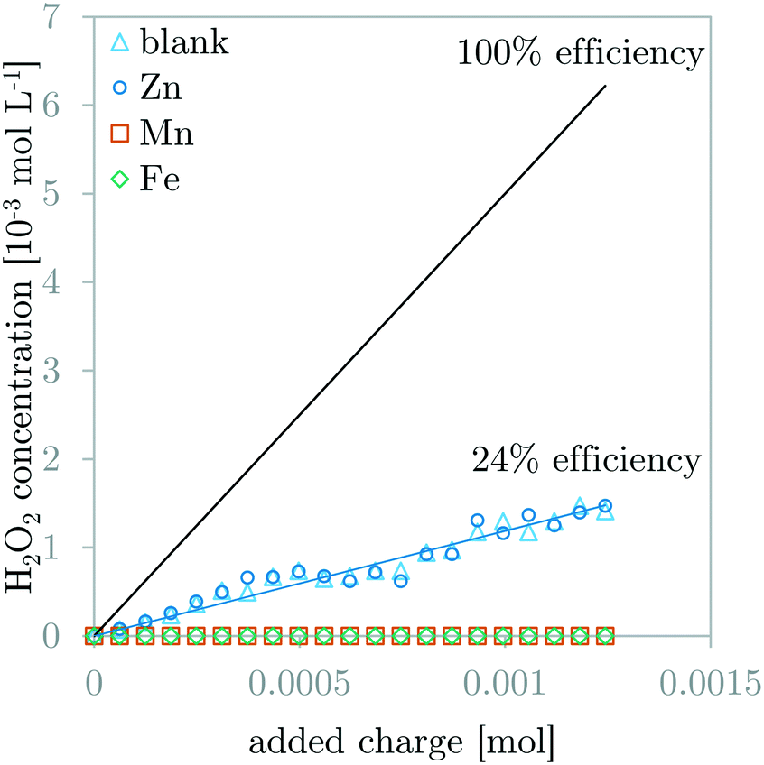 | ||
| Fig. 4 Comparison of H2O2 concentration measurements during GDEx experiments of a blank solution and solutions with ZnCl2, MnCl2, or FeCl2. The H2O2 production efficiency (24%) for the case of the blank solution and the ZnCl2 solution are the same (blue interpolation line). The 100% efficiency line is indicated for comparison. | ||
Dynamic pH behavior
The expected shape of the dynamic pH curves was briefly discussed in the Introduction (Fig. 1). Fig. 5 compares the dynamic pH measurements of the galvanostatic GDEx experiments with the AT experiments for the solutions with ZnCl2, MnCl2, and FeCl2. Fig. 5a and b compare the results of AT and GDEx respectively for solutions with ZnCl2, MnCl2, or FeCl2. The shapes of the dynamic pH curves are all in line with the expectations. Fig. 5c–e compare GDEx and AT for solutions with ZnCl2, MnCl2, or FeCl2 respectively. | ||
| Fig. 5 Comparison of the dynamic pH curves for ZnCl2, MnCl2 and FeCl2 for AT (a) and GDEx (b). Comparison of the dynamic pH curves for AT and GDEx for ZnCl2 (c), MnCl2 (d) and FeCl2 (e). | ||
For AT, stage 1 and 2 ended as expected upon the addition of respectively 10−4 mol and 1.1 10−3 mol of OH− (Fig. 5a). Also, the theoretical shape of the curve corresponds to the experimental shape of the curve for the cases of Zn and Mn. For Fe, a small deviation of this shape is observable: besides the main precipitation plateau, a short inclination before the main plateau is visible (Fig. 5a). This is attributed to the fact that small amounts of Fe3+ may have remained or may have formed in the prepared solution. These Fe3+ ions tend to precipitate as Fe3O4 which is known to precipitate at lower pH than Fe(OH)2.20
For GDEx, stage 1 and 2 do not end as expected, even though the shape of the curves are similar to those of AT (Fig. 5b). Comparison of AT and GDEx is easier for each metal separately (Fig. 5c–e), as such four major differences are observable: (1) the first inflection point (i.e., the end of stage 1) appears somewhat later for GDEx than for AT (Fig. 5c–e), (2) the second inflection point (i.e., the end of stage 2) appears much later for GDEx than for AT (Fig. 5c–e), (3) while the value of the precipitation pH for Zn and Mn differs little between AT and GDEx, the value of the precipitation pH for Fe decreases significantly (Fig. 5e), and (4) the delay of the first inflection point of Fe is higher than for Zn and Mn (Fig. 5b). Observation (1) and (2) can be discussed in light of the electrochemical production of OH− and HO2−. One could argue that the addition-efficiency of OH− might be lower than 100% due to the production of HO2−. This is correct, however, because the bulk pH remains low enough during the experiment (pKH2O2 = 11.62 (ref. 20)), the produced HO2− will remove protons by protonating to become H2O2. Therefore, the theoretical addition of OH− can be regarded as 100% efficient, as long as the pH is sufficiently low. Nevertheless, observations (1) and (2) imply an efficiency of less than 100%. A closer look at the second inflection point demonstrates that the delay is independent of the metal ion: stage 3 starts simultaneously for each case (Fig. 5b). The individual comparison of GDEx and AT for each metal case demonstrates that the delay grows over time (Fig. 5c–e). In the case of the first inflection point, AT and GDEx differ significantly less than in the case of the second inflection point. Moreover, because of this, the precipitation plateau is longer than is theoretically possible (i.e., 2 times the amount of metal ion in solution). All these observations point towards the characteristics of the GDEx process itself, rather than the characteristics of the electrolytes. One possible explanation is that the delay is caused by the time-dependent accumulation of OH− and HO2− in the pores of the gas-diffusion electrode. This accumulation would then cause a high pH in the electrode pores.31 The built-up of these species slows down the flux of these species into the bulk of the electrolyte, which is registered as a delay of the measured pH during GDEx compared to during AT. This explanation is currently under investigation, with preliminary results that are in line with the hypothesis.32
Observations (3) and (4) are specific to the case of GDEx of FeCl2. The decrease in the precipitation pH indicates a change in the chemical reaction. This change in chemical reaction is caused by the oxidation of Fe2+ to Fe3+ by H2O2.8,17 The occurrence of both Fe3+ and Fe2+ is known to result in the coprecipitation of Fe2+ and Fe3+ as Fe3O4.33 This composition was also confirmed by XRD (Fig. 7c). The additional OH− needed to precipitate Fe3+ instead of Fe2+ is produced during the oxidation reaction of Fe2+ with H2O2. For this reason, the length of the plateau remains unchanged compared to the cases of Zn and Mn (Fig. 5b). The slightly larger shift of the first inflection point for Fe (Fig. 5e) compared to Mn and Zn (Fig. 5c and d), is most probably related to pre-precipitation of Fe3O4 in the flow cell. Because of a slightly higher pH in the flow cell, precipitation criteria are met earlier than in the reservoir. The OH− used for pre-precipitation does not contribute to an increase in the pH, which thus causes an additional delay.
Potentiograms of galvanostatic GDEx experiments
The GDE (cathode) potential was measured during galvanostatic GDEx experiments (Fig. 6). The potential remains very stable over the duration of an experiment. This galvanostatic potential is dictated by the electrochemical reactions in the porous GDE, being primarily the oxygen-reduction reactions (eqn (1)–(3)). At first glance, the stable potential is odd because it shows (1) an apparent contradiction to the Nernst equation, which dictates that the potential depends on the pH (which changes over time in the bulk solution), and (2) a limited effect of the initial solution composition (i.e., different metal ions). The first observation can be understood with the same explanation as the delay of the rise in pH (discussed above). The electrode potential depends on the pH at the reactive surface, not the pH in the bulk of the solution. Since the ORRs are producing OH− and the mass transfer of this produced OH− to the bulk is compromised by the porous nature of the electrode, the OH− concentration at the reactive surface (and therefore the pH) increases rapidly and remains high during the experiment. When the OH− concentration in the GDE reaches a level that is similar to the concentration of the supporting electrolyte ions, an intricate combination of mass transfer phenomena (i.e., a balance between diffusion and migration of both reaction products and supporting electrolyte ions) will dictate the exact OH− concentration, which then dictates the electrode potential. The observed stable potential within the first 50 seconds of the experiment, indicates such balance is reached rather quickly. The second observation can also be attributed to the high pH at the surface of the GDE. The effect of the metal ions in solution is unlikely to influence the electrode potential, because of the high concentration and outgoing flux of OH− in the vicinity of the GDE, and the low concentration of the metal ions in solution compared to this OH− concentration and the concentration of the supporting NaCl electrolyte. This high concentration of OH− and low concentration of metal ions is expected to produce a precipitation reaction at a distance away from the GDE at the far-end of the diffusion layer. This then prevents metal ions from reaching the surface of the GDE and is therefore unlikely to change the cathode potential. The average potential differences between the different experiments were maximum 5 mV. In our experience with the VITO CoRE® electrode, such small differences cannot be attributed to a change of the type of metal ion in solution. These inter-experimental changes in potential need to be accepted as experimental inaccuracies attributed to minor changes in the interface between the solution and the porous electrode in between different experiments. | ||
| Fig. 6 Potentiograms of galvanostatic GDEx experiments for solutions with ZnCl2, MnCl2 or FeCl2. Insert gives a comparison in a smaller potential range. | ||
Composition of the precipitates
The composition of the precipitates was characterized by XRD. Fig. 7 compares the AT and GDEx precipitates for the cases of Zn, Mn, and Fe. In the case of zinc, the XRD pattern could be identified as mainly Zn(OH)2 (ref. 34 and 35) in both the AT and GDEx case (Fig. 7). However, in the GDEx case, some of the peaks corresponded to the dehydrated ZnO phase36 (Fig. 7a). The XRD pattern for manganese could be identified as Mn3O4 (ref. 10 and 37) for both the AT and GDEx cases (Fig. 7b). The XRD pattern for iron was identified as that of FeO (ref. 38–40) in the case of AT and as that of Fe3O4 (ref. 38 and 41) in the case of GDEx (Fig. 7c). Without oxidation, the precipitation reaction of the metal ions with OH− is expected to yield precipitates of Zn(OH)2, Mn(OH)2, and Fe(OH)2, or their dehydrated forms (i.e., ZnO, MnO, and FeO), for the cases of Zn, Mn and Fe, respectively. In the case of zinc, the composition was as expected, with Zn(OH)2 as the main phase, with or without some dehydrated ZnO. In the case of manganese, the observation of Mn3O4 rather than Mn(OH)2 is in line with the color observations during the post-treatment washing steps. In the case of iron, visual observations of the precipitates after processing already hinted at the occurrence of a different composition. For AT and GDEx, this deviation from the expected composition of Fe(OH)2 or FeO is assumed to be caused by different phenomena. In the case of AT, FeO showed light orange color, most likely caused by superficial oxidation to Fe2O3, which cannot be observed with XRD. In the case of GDEx, presumably Fe(II) is for the most part oxidized by the H2O2 produced during the process. This would be in agreement with the readily observed dark brown precipitates and the fact that no H2O2 could be measured during the process.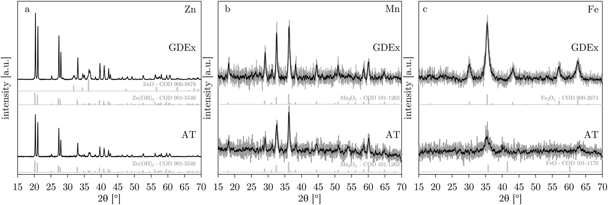 | ||
| Fig. 7 XRD patterns for AT and GDEx for solutions with ZnCl2 (a), MnCl2 (b) or FeCl2 (c). XRD reference patterns (from the crystallography open database – COD42–47) are shown below the AT and GDEx patterns for the detected phases. | ||
Size and morphology of the precipitates
Fig. 8 shows the SEM micrographs of the obtained precipitates. In all cases, the precipitate was highly agglomerated. For the cases of Zn and Mn, the morphology of the particles processed by GDEx differ little with those processed by AT (Fig. 8a and d for Zn, and Fig. 8b and e for Mn). In the cases of Zn, irregular sheet-like particles were identifiable, albeit difficult. The size of these particles could not be meaningfully determined by observing SEM. In the cases of Mn, spherical nanoparticles with an estimated size in the order of 50 nm or lower (SEM) were easily observed. Because these nanoparticles are spherical, the Scherrer equation48 could be used to estimate the crystallite size at 21 nm for AT and 22 nm for GDEx, from the XRD patterns (Fig. 7b). The similarities for AT and GDEx, for the cases of Zn and Mn, are in line with the other observations: similar precipitate color, similar composition, and similar precipitation behavior observed by dynamic pH measurements. Except for the fact that no H2O2 could be measured in the case of GDEx of MnCl2, it appears that the GDEx and AT processes are equivalent for the synthesis of Zn(OH)2 and Mn3O4 nanoparticles, within the confines of our process conditions. Given that AT is used as a benchmark process for alkaline precipitation and GDEx appears to be equivalent to AT for our solutions of MnCl2 and ZnCl2, presumably GDEx only elicits alkaline precipitation in these cases, and not oxidation-assisted alkaline precipitation. The reason for the fact that no H2O2 could be measured in the case of Mn is not entirely clear, but one possible explanation could be the effective catalytic decomposition of H2O2 on Mn(OH)2.49 | ||
| Fig. 8 SEM images of the precipitates synthesized with AT (a–c) and GDEx (d–f) for the cases of ZnCl2 (a and d), MnCl2 (b and e), and FeCl2 (c and f). | ||
In contrast to the Zn and Mn cases, for the case of Fe, the particles processed by AT and GDEx differed significantly in size and morphology (Fig. 8c and f). While the FeO particles synthesized with AT are tile-shaped and with a long-axis length in the order of 200 nm (Fig. 8c), the Fe3O4 nanoparticles synthesized by GDEx are spherical with a diameter in the order of 20 nm or lower (Fig. 8f). These particles are only just visible by SEM (inset Fig. 8f). Because these Fe3O4 nanoparticles are spherical, the crystallite size could be estimated at 10 nm from the XRD pattern (Fig. 7c), using the Scherrer equation.48 As for manganese species, catalytic decomposition of H2O2 by iron species is known.50,51 However, in combination with a composition change, this large size and morphology difference is a strong indication that an additional mechanism plays a role in the case of iron. This additional mechanism could be the oxidation-assisted alkaline precipitation (Ox-AP) elicited by GDEx in the case of iron, rather than only alkaline precipitation (AP) as is observed in the cases of zinc and manganese. The occurence of Ox-AP would be in line with our expectations, given our experience with the Ox-AP of Fe2+ in a chemical Y-junction reactor8 and the controllable synthesis of iron oxide nanoparticles with GDEx.17 In our exploratory study on AP and Ox-AP,8 the size decrease between both processes was assigned to improved condensation (olation and oxolation) kinetics as the result of oxidation of the metal ion during the precipitation process. Nevertheless, such a large size difference between alkaline precipitation and oxidation-assisted alkaline precipitation was not yet observed. One possible explanation for this would be the fact that in this work, Ox-AP and AP result in precipitates of species with other compositions, while in the previous work8 the precipitates had the same composition. Species with different compositions have different solubility products. Because Fe3O4 (Ksp,Fe3O4 = 10−108.6 (ref. 52)) has a much lower solubility than FeO (Ksp,FeO = 10−14.5 (ref. 53)), the supersaturation in the GDEx process will be significantly higher than in the AT process, as a result of the oxidation of Fe(II) to Fe(III). It has long been established from classic nucleation theory that higher supersaturation results in smaller (nano)particles.54–56 Therefore, the large size difference, between the nanoparticles synthesized by AT (eliciting AP) and the nanoparticles synthesized with GDEx (eliciting Ox-AP), could be explained by the combined effect of the improved condensation kinetics (due to Ox-AP) and the increased supersaturation (due to a change in composition) in the GDEx process.
Conclusions
Gas-diffusion electrocrystallization (GDEx) was benchmarked against alkaline titration (AT) to demonstrate the potential of GDEx to elicit oxidation-assisted alkaline precipitation (Ox-AP) of metal (oxy)(hydr)oxide nanoparticles. The comparison of GDEx with AT for solutions of ZnCl2, MnCl2, or FeCl2 showed that GDEx resulted in the synthesis of nanoparticles meeting expectations of an Ox-AP mechanism, but only in the case of FeCl2. In this case, GDEx synthesized Fe3O4 nanoparticles with a much smaller size than the FeO nanoparticles synthesized with AT. The smaller sizes obtained with GDEx presumably result from the oxidation of Fe(II) to Fe(III) by H2O2 or HO2−, which potentially combines the effect of improving condensation kinetics and drastically increasing the supersaturation, both known as size-determining parameters. In the cases of ZnCl2 and MnCl2, AT and GDEx synthesized similar nanoparticles. Therefore, in these cases, AT and GDEx were considered equivalent processes and GDEx only elicited alkaline precipitation rather than oxidation-assisted alkaline precipitation. Our group is currently exploring GDEx into more detail to further unravel its potential and to expand the library of metal (oxy)(hydr)oxide nanoparticles that might benefit a size reduction from being produced with GDEx rather than AT.Conflicts of interest
There are no conflicts to declare.Acknowledgements
S. E. and R. P. acknowledge funding from Strategic Initiative Materials (SIM) in Flanders, within the recyclable materials MaRes program, under grant agreement no 150626 (Get-A-Met project). R. P. acknowledges VITO Strategic PhD grant funding no 1510774. J. F. and X. D. B. acknowledge funding from the European Union's Horizon 2020 research and innovation programme under grant agreement no 654100 (CHPM2030 project). The authors thank the funding by the EU in the framework of Horizon 2020 TOPIC SC5-13-2016 grant agreement no 730224 (PLATIRUS project).Notes and references
- M. Wächtler, L. González, B. Dietzek, A. Turchanin and C. Roth, Phys. Chem. Chem. Phys., 2019, 21, 8988–8991 RSC.
- S. Mallakpour and M. Madani, Prog. Org. Coat., 2015, 86, 194–207 CrossRef CAS.
- A. Akbari, M. Amini, A. Tarassoli, B. Eftekhari-Sis, N. Ghasemian and E. Jabbari, Nano-Struct. Nano-Objects, 2018, 14, 19–48 CrossRef CAS.
- C. Goswami, K. K. Hazarika and P. Bharali, Mater. Sci. Energy Technol., 2018, 1, 117–128 Search PubMed.
- J. M. George, A. Antony and B. Mathew, Microchim. Acta, 2018, 185, 1–26 CrossRef CAS PubMed.
- M. S. Chavali and M. P. Nikolova, SN Appl. Sci., 2019, 1, 1–30 Search PubMed.
- J. A. Rodríguez and M. Fernández-García, Synthesis, Properties, and Applications of Oxide Nanomaterials, John Wiley & Sons, New York, 2007 Search PubMed.
- S. G. Eggermont, A. Rua-Ibarz, K. Tirez, X. Dominguez-Benetton and J. Fransaer, RSC Adv., 2019, 9, 29902–29908 RSC.
- C. Henrist, J.-P. Mathieu, C. Vogels, A. Rulmont and R. Cloots, J. Cryst. Growth, 2003, 249, 321–330 CrossRef CAS.
- B. G. S. Raj, A. M. Asiri, J. J. Wu and S. Anandan, J. Alloys Compd., 2015, 636, 234–240 CrossRef.
- M. Mohapatra and S. Anand, Int. J. Eng. Sci. Technol., 2010, 2, 127–146 Search PubMed.
- S. Hasany, I. Ahmed, J. Rajan and A. Rehman, Nanosci. Nanotechnol., 2012, 2, 148–158 CrossRef.
- Q. Zhang, K. Zhang, D. Xu, G. Yang, H. Huang, F. Nie, C. Liu and S. Yang, Prog. Mater. Sci., 2014, 60, 208–337 CrossRef CAS.
- S. G. F. Eggermont, R. Prato, X. Dominguez-Benetton and J. Fransaer, J. Environ. Chem. Eng., 2019, 103569 Search PubMed.
- J.-P. Jolivet, M. Henry and J. Livage, Metal oxide chemistry and synthesis: from solution to solid state, Wiley-Blackwell, 2000 Search PubMed.
- J.-P. Jolivet, S. Cassaignon, C. Chanéac, D. Chiche and E. Tronc, J. Sol-Gel Sci. Technol., 2008, 46, 299–305 CrossRef CAS.
- R. A. Prato, V. Van Vught, S. Eggermont, G. Pozo, P. Marin, J. Fransaer and X. Dominguez-Benetton, Sci. Rep., 2019, 9, 1–11 CAS.
- R. A. Prato, V. Van Vught, K. Chayambuka, G. Pozo, S. Eggermont, J. Fransaer and X. Dominguez-Benetton, et al. , J. Mater. Chem. A, 2020, 8, 11674–11686 RSC.
- M. Tarasevich, A. Sadkowski and E. Yeager, in Comprehensive treatise of electrochemistry, Springer, 1983, pp. 301–398 Search PubMed.
- M. Pourbaix, Atlas of Electrochemical Equilibria in Aqueous Solution, NACE, Houston, TX, 1974 Search PubMed.
- R. C. Burgos-Castillo, A. Garcia-Mendoza, Y. Alvarez-Gallego, J. Fransaer, M. Sillanpää and X. Dominguez-Benetton, Nanoscale Adv., 2020, 2, 2052–2062 RSC.
- Y. Kiros, M. Pirjamali and M. Bursell, Electrochim. Acta, 2006, 51, 3346–3350 CrossRef CAS.
- I. Moussallem, J. Jörissen, U. Kunz, S. Pinnow and T. Turek, J. Appl. Electrochem., 2008, 38, 1177–1194 CrossRef CAS.
- P. Woltering, P. Hofmann, F. Funck, R. Kiefer, U.-S. Baeumer, D. Donst and C. Schmitt, ThyssenKrupp Techforum, 2013, 18–23 Search PubMed.
- M. Paidar, V. Fateev and K. Bouzek, Electrochim. Acta, 2016, 209, 737–756 CrossRef CAS.
- Y. Alvarez-Gallego, X. Dominguez-Benetton, D. Pant, L. Diels, K. Vanbroekhoven, I. Genné and P. Vermeiren, Electrochim. Acta, 2012, 82, 415–426 CrossRef CAS.
- D. Lide, CRC Handbook of Chemistry and Physics, 90th edn, 2009 Search PubMed.
- H. Boumaiza, R. Coustel, G. Medjahdi, C. Ruby and L. Bergaoui, J. Solid State Chem., 2017, 248, 18–25 CrossRef CAS.
- Z.-R. Tian, W. Tong, J.-Y. Wang, N.-G. Duan, V. V. Krishnan and S. L. Suib, Science, 1997, 276, 926–930 CrossRef CAS.
- Darminto, M. N. Cholishoh, F. A. Perdana, M. A. Baqiya, Mashuri, Y. Cahyono and Triwikantoro, Preparing Fe3O4 Nanoparticles from Fe2+ Ions Source by Co-Precipitation Process in Various pH, 2011, vol. 1415, pp. 234–237 Search PubMed.
- K. Sundmacher and T. Schultz, J. Appl. Electrochem., 2005, 35, 1171–1181 CrossRef CAS.
- S. G. Eggermont, Electroprecipitation of Metal ions from aqueous electrolytes: kinetic study and process performance, Unpublished PhD thesis, KU Leuven, 2020 Search PubMed.
- R. Massart, IEEE Trans. Magn., 1981, 17, 1247–1248 CrossRef.
- M. Wang, L. Jiang, E. J. Kim and S. H. Hahn, RSC Adv., 2015, 5, 87496–87503 RSC.
- A. K. Zak, W. A. Majid, M. E. Abrishami and R. Yousefi, Solid State Sci., 2011, 13, 251–256 CrossRef.
- M. Wang, Y. Zhou, Y. Zhang, S. H. Hahn and E. J. Kim, CrystEngComm, 2011, 13, 6024–6026 RSC.
- Y. Chang, X. Xu, X. Luo, C. Chen and D. Yu, J. Cryst. Growth, 2004, 264, 232–236 CrossRef CAS.
- J.-H. Jang and S. L. Brantley, Environ. Sci. Technol., 2009, 43, 1086–1090 CrossRef CAS PubMed.
- S. Sharma, J. Vargas, K. Pirota, S. Kumar, C. Lee and M. Knobel, J. Alloys Compd., 2011, 509, 6414–6417 CrossRef CAS.
- W. Jiang, F. Liang, J. Wang, L. Su, Y. Wu and L. Wang, RSC Adv., 2014, 4, 15394–15399 RSC.
- J. Xu, H. Yang, W. Fu, K. Du, Y. Sui, J. Chen, Y. Zeng, M. Li and G. Zou, J. Magn. Magn. Mater., 2007, 309, 307–311 CrossRef CAS.
- R. T. Downs and M. Hall-Wallace, Am. Mineral., 2003, 88, 247–250 CrossRef CAS.
- S. Gražulis, D. Chateigner, R. T. Downs, A. F. T. Yokochi, M. Quirós, L. Lutterotti, E. Manakova, J. Butkus, P. Moeck and A. Le Bail, J. Appl. Crystallogr., 2009, 42, 726–729 CrossRef PubMed.
- S. Gražulis, A. Daškevič, A. Merkys, D. Chateigner, L. Lutterotti, M. Quirós, N. R. Serebryanaya, P. Moeck, R. T. Downs and A. Le Bail, Nucleic Acids Res., 2012, 40, D420–D427 CrossRef PubMed.
- S. Gražulis, A. Merkys, A. Vaitkus and M. Okulič-Kazarinas, J. Appl. Crystallogr., 2015, 48, 85–91 CrossRef PubMed.
- A. Merkys, A. Vaitkus, J. Butkus, M. Okulič-Kazarinas, V. Kairys and S. Gražulis, J. Appl. Crystallogr., 2016, 49, 292–301 CrossRef CAS PubMed.
- M. Quirós, S. Gražulis, S. Girdzijauskaitė, A. Merkys and A. Vaitkus, Journal of Cheminformatics, 2018, 10, 1–17 CrossRef PubMed.
- P. Scherrer, in Kolloidchemie Ein Lehrbuch, Springer, 1912, pp. 387–409 Search PubMed.
- S. Jiang, W. Ashton and A. Tseung, J. Catal., 1991, 131, 88–93 CrossRef CAS.
- S.-S. Lin and M. D. Gurol, Environ. Sci. Technol., 1998, 32, 1417–1423 CrossRef CAS.
- M. Pereira, L. Oliveira and E. Murad, Clay Miner., 2012, 47, 285–302 CrossRef CAS.
- J. W. Ball and D. K. Nordstrom, Wateq4f–User's Manual with Revised Thermodynamic Data Base and Test Cases for Calculating Speciation of Major, Trace and Redox Elements in Natural Waters, 1991 Search PubMed.
- J. Johnson, G. Anderson and D. Parkhurst, Database thermo. com. V8. R6. 230, Rev. 1-11, Lawrence Livermore Natl. Lab., Livermore, California, 2000 Search PubMed.
- A. E. Nielsen, Kinetics of Precipitation, Pergamon, Oxford, London, 1964, vol. 18 Search PubMed.
- J. Dirksen and T. Ring, Chem. Eng. Sci., 1991, 46, 2389–2427 CrossRef CAS.
- G. Demopoulos, Hydrometallurgy, 2009, 96, 199–214 CrossRef CAS.
| This journal is © The Royal Society of Chemistry 2021 |