
 Open Access Article
 This Open Access Article is licensed under a
 Creative Commons Attribution 3.0 Unported Licence
Oscillating droplet reactor – towards kinetic investigations in heterogeneous catalysis on a droplet scale†
Torsten
Klement‡
 a,
Schirin
Hanf‡
b,
Fabian
Wolff
a,
Norbert
Kockmann
c,
Stephan A.
Schunk
*b and
Thorsten
Röder
*a
a,
Schirin
Hanf‡
b,
Fabian
Wolff
a,
Norbert
Kockmann
c,
Stephan A.
Schunk
*b and
Thorsten
Röder
*a
aMannheim University of Applied Sciences, Institute of Chemical, Process Engineering, Paul-Wittsack-Straße 10, 68163 Mannheim, Germany. E-mail: t.roeder@hs-mannheim.de
bhte GmbH, Kurpfalzring 104, 69123 Heidelberg, Germany. E-mail: stephan.schunk@hte-company.de
cTechnische Universität Dortmund, Fakultät für Bio- und Chemieingenieurwesen, Apparatedesign, Emil-Figge-Straße 68, 44227 Dortmund, Germany
First published on 15th April 2021
Abstract
In this work we present a new concept of a millistructured capillary reactor setup for contactless kinetic measurements via in-line Raman spectroscopy for three phase reactions in single slugs. With this setup, it is possible to decouple the residence time from the volumetric flow and the reactor length. Catalysts palladium supported on carbon, in the form of Pd nano-particles on graphite fibres as well as in the form of a fixed bed catalysts as particulates of porous carbon, were utilised. A 3D-printed catalyst holder was designed to integrate the catalyst powder with a fixed bed in the capillary. The proof of concept was demonstrated using two test reactions, namely the hydrogenation of nitrobenzene and cinnamaldehyde. Multiple measurements were carried out and a good reproducibility was achieved, which lays the foundation for the application of this 3-phase oscillating droplet reactor as a tool for assessing kinetics with respect to heterogeneously catalysed three phase reactions.
Introduction
Around 80% of our today's chemicals are produced in catalytic processes, from which most involve the use of heterogeneous catalysts.1 In order to guarantee an economical and safe process development concerning heterogeneously-catalysed reactions, detailed knowledge about the kinetic properties of such chemical reactions is the key. This knowledge is not only advantageous regarding sustainability and safety, but it is also the basis for an optimal process and plant design.2For the kinetic investigation of heterogeneously catalysed gas phase reactions, usually fixed bed reactors equipped with online analytical techniques are employed.3 In this context, the parallelisation of such setups enables a rapid parameter screening and greatly reduces the amount of time that is required to gain comprehensive kinetic data.4–7 Kinetic studies of heterogeneously catalysed gas–liquid hydrogenation reactions, however, are in many cases performed using discontinuously running batch autoclaves. Although reactions carried out in batch setups can easily be monitored by the gas consumption and in-line analytics affording high quality data under very good reproducibility, kinetic studies in batch autoclaves are not easily performed under differential conditions and usually have a high footprint of resources with respect to materials and personal resources. Further, the handling of large amounts of flammable gases, such as hydrogen, and an iso-thermal reaction control for very exothermic reactions can be very challenging.2 Therefore, continuously running microreactors, like the H-Cube,8,9 were found to be a good alternative due to the high specific interfacial areas, through which an efficient heat and mass transport can be ensured.10,11 Also micro-structured catalyst beds have been developed in order to increase the transport rates.12 By the use of microreactors, only low amounts of reagents are consumed, which also enables the handling of instable and dangerous intermediates without any safety concerns. A further benefit of microreactors is the very defined and narrow residence time distribution within the reactor. This also gave rise to the use of microreactors in alternative fields, such as the synthesis of nano materials, such as quantum dots and complex oxides and zeolites.13–15 Nevertheless, for very slow reactions, (i.e. inherently small reaction rates) either low flow rates or long reactors are required to achieve sufficient degrees of conversion.16 In order to overcome this challenge, a 3-phase microreactor, in which an oscillating droplet is passing a catalyst in a millimetre scaled capillary, was developed. Up to date, such oscillation setups were mainly applied to 2-phase systems17–21 and in the context of the microfluidic synthesis of nanocrystals22,23 starting from a solution-phase.
In the present study, the oscillation concept for the measurement of reaction kinetics is extended towards a 3-phase system, in which the catalyst is present either in the form of a non-porous fibre or as a fixed catalyst bed of a defined particle size (Fig. 1).24 This concept combines the advantages of a batch autoclave, namely the flexibility, and the pros of a microreactor, such as the defined reaction conditions. Also, by using this setup, the residence time can be decoupled from the volumetric flow rate and the reactor length. Therefore, the oscillating droplet reactor is also a useful tool for the kinetic investigation of very slow reactions. To demonstrate the feasibility of the oscillating droplet reactor concept as a tool for obtaining kinetic data, the hydrogenation reactions of nitrobenzene and of cinnamaldehyde were selected as exemplary test reactions. Therefore, a droplet, consisting of the starting material and solvent, was oscillated within a capillary filled with hydrogen passing a catalyst. To monitor the reaction progress within the 3-phase oscillation reactor, in-line Raman spectroscopy was utilised.
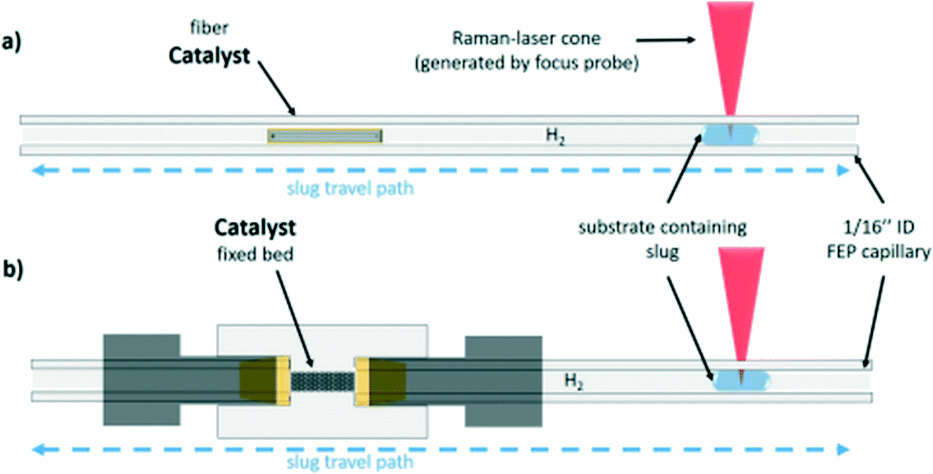 | ||
| Fig. 1 Representation of the capillary of the 3-phase oscillation droplet reactor setup. a) Shows the setup for the carbon fibre based and b) shows the fixed bet setup for bulk catalyst measurement. | ||
Results and discussion
Oscillating droplet reactor setup
As mentioned before, a 3-phase oscillating droplet reactor setup was developed to enable kinetic investigations of heterogeneously catalysed reactions regarding three phase reactions. The setup consists of a FEP-capillary (diameter 1.59 mm), which was filled with a gas mixture (20% H2, 80% N2 or pure H2) as a continuous phase, a Pd/C catalyst in different forms and a 20 μL droplet containing the starting material and the solvent. Since the drop fills the entire cross-sectional area of the capillary and since the length of the drop is significantly larger than the diameter (6.25 times the diameter), the drop is referred to as a slug.25 Driven by two contrary working syringe pumps, the slug is oscillated between the Raman probe and the catalyst (superficial velocity = 0.7 mm s−1), and after each oscillation cycle, the starting material conversion was monitored via Raman spectroscopy (Fig. 2). For further explanations of the reaction setup and the experimental procedure see the ESI,† sections S1 and S2. The period of one oscillation is about 36 s. A slower movement leads to no change in the measured kinetics, whereas a higher superficial velocity may cause instability of the droplets. Approximately three spectra were recorded to ensure that at least one spectrum from the slug centre is taken. The main advantage of using contactless in-line Raman spectroscopy lies in its universal application for the analysis of a broad compound spectrum. To evaluate the slug stability over the measurement time, the solvent signal was monitored, which should in theory show a constant intensity. The Raman spectra over time representation can be found in section S3 of the ESI.† Both visual inspection and time analyses of the Raman spectra did not reveal any decrease in the volume of the droplets. An exemplary slug length analysis can be found in Fig. S7 in the ESI.† Since the vapour pressures of the reactants are several orders of magnitude lower than those of the solvent's methanol or ethanol, it can be assumed that no significant amounts of reactant or solvent evaporated despite the large droplet surface. Also, no Pd leaching of the fibre catalyst occurred, as the Pd content, determined by ICP-OES measurements before and after the catalytic reaction, showed (see the ESI,† section S4).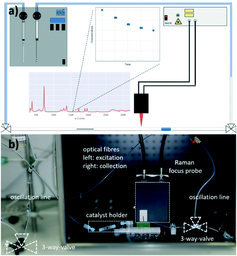 | ||
| Fig. 2 a) Schematic representation of the pendular tube for guiding the droplets. The same applies to the Raman focus probe and the measured concentration profile (double determination) of two contacts on the catalyst. b) Photography of the set-up (corresponding to a). | ||
For catalytic test reactions, the hydrogenation of nitrobenzene to aniline in methanol and cinnamaldehyde to hydrocinnamaldehyde in ethanol as solvent were selected (Scheme 1). The progress of these reactions was evaluated by looking at the intensity decay of the characteristic nitrobenzene signal at 1350 cm−1 and the characteristic cinnamaldehyde signal at 1630 cm−1, respectively (see the ESI,† section S3 for further information). Since the product selectivities of the hydrogenation reactions are close to 100%, the monitoring of the decrease of the starting material amount was taken as feasible proportional measure for the intrinsic reaction rate of the reaction. In the case of the hydrogenation of cinnamaldehyde (Scheme 1, reaction b), exclusively the C![[double bond, length as m-dash]](https://www.rsc.org/images/entities/char_e001.gif) C bond is hydrogenated, whereas the aldehyde group remains untouched. In the hydrogenation of nitrobenzene as well as the hydrogenation of cinnamaldehyde, the benzene core is not hydrogenated. Catalysts either Pd supported on graphite fibres or Pd supported on carbon with four different grain sizes (125–160 μm, 160–250 μm, 315–500 μm, and 500–1000 μm) were explored. In the case of the Pd supported carbon fibres, about 0.003 wt% Pd were present, whereas in the case of the powder catalyst, Pd loadings of 2 and 5 wt% on carrier were utilised. The catalyst syntheses and characterisations are described in detail in the ESI,† section S4. For the implementation of a fixed bed within the FEP-capillary, a 3D-printed catalyst holder was developed. To keep the powder catalyst fixed within the catalyst holder, both sides of the holder were restricted with 100 μm stainless steel metal meshes. The hydrogenation reactions were carried out at hydrogen partial pressures in the range of 0.02–0.40 MPa. In all tests the catalyst was pre-activated by flushing the entire setup with hydrogen (2 ml min−1) for 30 min.
C bond is hydrogenated, whereas the aldehyde group remains untouched. In the hydrogenation of nitrobenzene as well as the hydrogenation of cinnamaldehyde, the benzene core is not hydrogenated. Catalysts either Pd supported on graphite fibres or Pd supported on carbon with four different grain sizes (125–160 μm, 160–250 μm, 315–500 μm, and 500–1000 μm) were explored. In the case of the Pd supported carbon fibres, about 0.003 wt% Pd were present, whereas in the case of the powder catalyst, Pd loadings of 2 and 5 wt% on carrier were utilised. The catalyst syntheses and characterisations are described in detail in the ESI,† section S4. For the implementation of a fixed bed within the FEP-capillary, a 3D-printed catalyst holder was developed. To keep the powder catalyst fixed within the catalyst holder, both sides of the holder were restricted with 100 μm stainless steel metal meshes. The hydrogenation reactions were carried out at hydrogen partial pressures in the range of 0.02–0.40 MPa. In all tests the catalyst was pre-activated by flushing the entire setup with hydrogen (2 ml min−1) for 30 min.
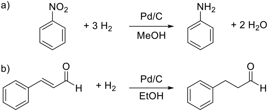 | ||
| Scheme 1 Catalytic test reactions. a) Hydrogenation of nitrobenzene to aniline and b) hydrogenation of cinnamaldehyde. | ||
Carbon fibre catalyst
To demonstrate the application of the 3-phase oscillating droplet reactor concept, a non-porous material was selected as a first example. The use of a non-porous material should guarantee a clearly defined “two-dimensional” catalyst system and rules out the limitations due to effects of mass transport. Therefore, graphite fibres were impregnated with Pd (0.003 wt%, see the ESI,† section S4 for further details). The system was validated using the hydrogenation of nitrobenzene as test reaction. Table 1 shows the reaction conditions including the catalyst substrate ratio.| Hydrogen partial pressure | 0.25 MPa |
| Initial substrate concentration | 100 mmol L−1 |
| Fibre weight | 3.4 mg |
| Pd-Amount | 29 ppm |
| Ratio Pd/substrate | 2.32 × 10⁻⁴ mol mol−1 |
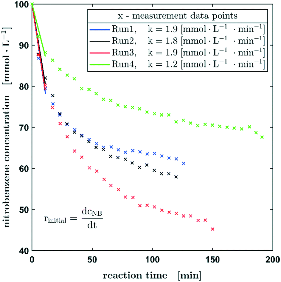
As described before, the reaction progress of the hydrogenation of nitrobenzene was monitored by the consumption of the latter starting material. In order to investigate the reproducibility of the setup, four consecutive reaction runs (on one fibre catalyst) were carried out at a hydrogen pressure of 0.25 ± 0.01 MPa and a nitrobenzene concentration of 200 mmol L−1 at the beginning of the reaction (Fig. 3). On the time axes in Fig. 3 the effective catalyst contact time is used and represents the time the droplet has full contact in average. The real time for measuring 17 points, as shown in Fig. 3, is about 103 min. From run 1 to 3 there is an obvious steady increase in the reaction rate, which is explained by increasing the catalyst wetting and activation of the active metal. The next runs (2 and 3) show a highly comparable and reproducible concentration profile over time. In further runs, the reaction rate coefficient decreases slightly, which can be caused by catalyst deactivation. Notice that there are approx. 10−9 mol palladium on the fibre, which might easily be affected by impurities resulting from hydrogen flushing between the runs or from the solvent or starting material. Also, poisoning of the catalyst by the formation of hydroxylamines could be a plausible explanation. In this context, Pd leaching can be excluded since no significant loss of Pd could be detected by ICP-OES measurements of the fibre catalyst before and after the catalytic reaction (see the ESI,† section S4). Overall, the results show a satisfactory reproducibility of the measurements using this oscillating droplet reactor, with only minor deviations.
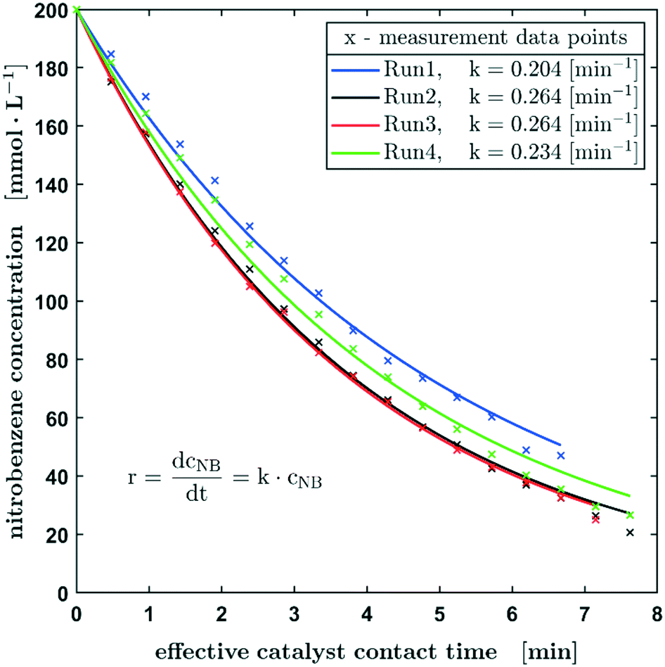 | ||
| Fig. 3 Reproducibility experiments based on the hydrogenation of nitrobenzene in methanol using one Pd carbon fibre catalyst. The starting conditions of the experiments shown are p0 = 0.25 ± 0.01 MPa, c0 = 200 mmol L−1, and 100% H2. | ||
Despite the complex mechanism and the numerous individual steps in the heterogeneously catalysed hydrogenation of nitrobenzene,26 the concentration curve can be described with the differential equation for a first-order reaction with respect to the nitrobenzene concentration. Using this effective kinetic parameter, the activity of different catalysts and the influence of reaction parameters, such as concentrations, can be described. The reaction constant is in the range of 0.204 min−1 and 0.264 min−1 with an average value of 0.242 min−1.
In Fig. 4, the normalised concentration profiles (X-1) of the hydrogenation of nitrobenzene with starting concentrations of 100 mmol L−1 and 200 mmol L−1 are shown. Assuming a first order reaction with respect to the nitrobenzene concentration, the initial concentration has no influence on the half-life. Considering the bandwidth of the calculated reaction constants (Fig. 3), the reaction constants can be regarded as equal for the different starting concentrations.
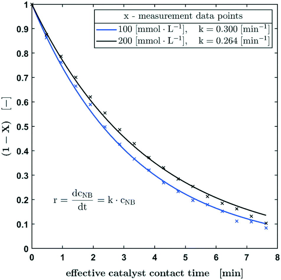 | ||
| Fig. 4 Normalised concentration profiles of the hydrogenation of nitrobenzene with starting concentrations of 100 mmol L−1 and 200 mmol L−1 in methanol. Reaction conditions: p0 = 0.25 ± 0.01 MPa, 100% H2. | ||
Further, the influence of the hydrogen pressure at the beginning of the reaction was investigated. The aim was hereby to evaluate whether mass transfer limitations are occurring during the diffusion of hydrogen gas into the slug. The results of this study are shown in Fig. 5 and a slightly different concentration profile becomes obvious when nearly doubling the hydrogen pressure from 0.25 to 0.40 MPa. The measurements shown so far suggested a rate law of the pseudo-first order, which can be attributed to the significant hydrogen excess relative to nitrobenzene even at a low hydrogen pressure of 0.25 MPa, in the case of the hydrogenation at a hydrogen pressure of 0.4 MPa, the pseudo-zero order rate law description might not be applicable over the whole concentration profile. Therefore, the reaction might be described better by a pseudo-zero-order rate law up to a nitrobenzene concentration of 74 mmol L−1, which is followed by a pseudo-first order reaction as soon as the concentration of the educts decreases further (see the ESI,† section S6 and Fig. S12). Such pseudo-zero-order reactions can be observed in certain concentration ranges at high reactant concentrations in heterogeneously catalysed reactions.27 However, despite the slight deviations of the fitted concentration from the measured concentration profile, a first-order reaction can still be applied in the case of the hydrogenation carried out at 0.4 MPa. This is also confirmed by the fact that the k0.40MPa/k0.25MPa ratio of 1.61 corresponds very well with the calculated pressure ratio of 1.6. The SEM images of the fibre material (ESI,† section S4) show a very low porosity. Likewise, no significant weight increase due to wetting could be detected. With regard to possible diffusion effects, pore diffusion can be neglected.
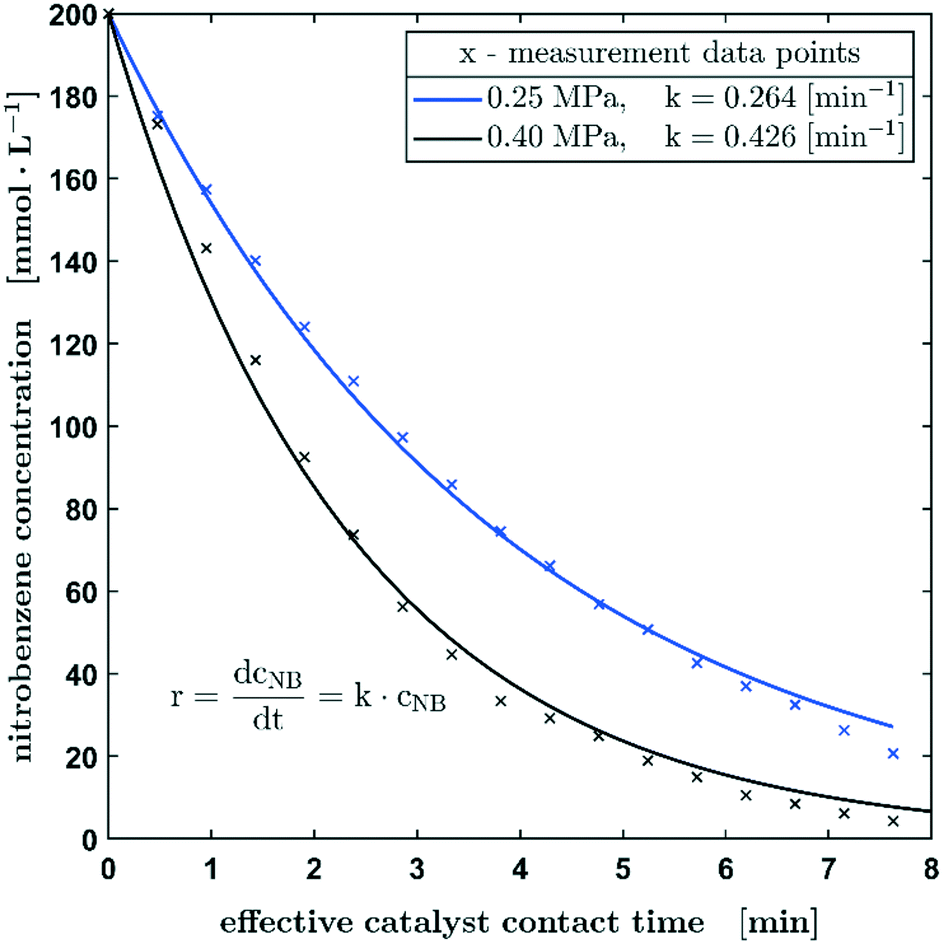 | ||
| Fig. 5 The concentration profile of the hydrogenation of nitrobenzene in methanol with starting pressures of 0.25 MPa and 0.40 MPa. Reaction conditions: c0 = 200 mmol L−1, 100% H2. | ||
Since no significant change of the kinetics could be detected when doubling the hydrogen pressures and since the change of the reaction constant k corresponds to the ratio of the pressure as described, it can be assumed that there is no mass transfer limitation caused by the diffusion effects on the hydrogen/liquid interface of the slug. In this context, the fact that sufficient hydrogen is still dissolved in the liquid methanol phase even when the slug is not in contact with the catalyst, must be considered. The effect of pre-charging the droplet with hydrogen is an inalienable feature of the process since hydrogen is used not only as a reactant but also as carrier gas within the capillary. Based on studies by Choudhary et al., who determined a Henry constant of 3.65 mmol L−1 bar−1 for the given system,28 a hydrogen concentration of 9.125 mmol L−1 in the slug can be estimated. The nitrobenzene conversion at the first catalyst pass and consequently the one with the highest reaction rate is 12.4 mmol L−1. This results in a hydrogen hold up of approx. 25% (stoichiometric coefficient = 3). Thus, a sufficiently large mass transfer from hydrogen into the methanol phase can be assumed, since 28 mmol L−1 hydrogen must be transferred during the reaction time on the catalyst. Without contact with the catalyst, the reaction stops, but there is obviously still contact between the gas and liquid phases.
Overall, it can be concluded, that the small amounts of palladium on the catalyst surface leads to a reasonable Pd/substrate ratio and overall reaction rates can be estimated with sufficient accuracy based on the measurable concentration ranges. Nevertheless, the low amount of Pd and the non-porous nature of the fibre lead to an exceedingly high atom efficiency. The normalised (by Pd weight) initial reaction rate r0 is approx. 7.4 mol L−1 s−1 mg−1.
Fixed bed catalyst
Since the results obtained from the 3-phase oscillating droplet reactor incorporating a non-porous fibre were very promising, the application towards more industrially relevant fixed bed catalysts with porous supports was a logical extension. Despite the fact that significantly higher amounts of catalyst (relative to the substrate) are used in this system than in batch reactors, catalyst activities should be comparable. The underlying micro kinetics can be assumed to be transferable between lab scale and industrial scale systems. Since the hydrodynamic effects and transport phenomena within a catalyst bed and the catalyst particle are very complex,29 the application of a fixed bed catalyst should give an insight into the properties of a catalyst, such as the influence of the particle size and the pore system and consequently the impact of pore diffusion processes. As shown in Fig. 1 the packed bed can be accomplished by using a 3D-printed holder (more detailed CAD graphics are available in the ESI,† section S2).However, going from a 2D to a 3D catalyst also complicates the data evaluation. In contrast to the fibre, where the reaction is stopped after the droplet is not in contact with the catalyst anymore, a part of the droplet remains on the fixed bed catalyst. This retained volume can be considered as the sum of the inter particle and the macro pore volume and it depends strongly on the particle size. The macro pore volume was determined experimentally (data available in the ESI,† section S4). The reactant fraction that remains on the fixed bed continues to react, while most of the droplet migrates under the probe to be measured. When the droplet passes the fixed bed again, complete mixing can be assumed. To take this effect into account, a linear regression of the concentration was performed, which considers the respective volumes and the oscillation times (Fig. S11 in the ESI† provides a graphical representation). Based on this interpolation procedure, the reaction progress of the hydrogenation of nitrobenzene is shown in Fig. 6. All reactions using fixed bed catalysts were carried out under atmospheric pressure, since an enhanced pressure reduces the slug stability on the catalyst bed. Table 2 shows the reaction conditions including the catalyst substrate ratio.
 | ||
| Fig. 6 Reproducibility experiments of the hydrogenation of nitrobenzene. Reaction conditions: p0 = 0.1 MPa, c0 = 100 mmol L−1 (nitrobenzene in methanol), 20% H2 in N2. An initial increase in the reaction rate can be observed. | ||
| Hydrogen partial pressure | 0.02 MPa |
| Initial substrate concentration | 100 mmol L−1 |
| Catalyst weight | 1.8 mg |
| Pd-Amount | 2 wt% |
| Ratio Pd/substrate | 0.17 mol mol−1 |
The decrease of the starting material follows exactly the same trend as observed for the Pd carbon fibre catalyst, whereas from experiment 1 to experiment 3 an enhanced reaction rate can be observed, probably due to the wetting of the catalyst bed and activation processes on the active metal, there is an obvious decrease in reaction rate for the fourth experiment. These experimental findings may be attributed to catalyst deactivation or poisoning processes. Obviously, further work is needed to elucidate these phenomena statistically in more detail and to provide a more in-depth knowledge about what is causing the decrease in reaction rate. However, at this point the aim of this setup is to provide a sufficient screening tool for the activity of certain catalysts.
As mentioned before, the experiments using the fixed bed catalysts were performed under atmospheric pressure. To reduce the reaction rate, instead of pure hydrogen gas, a mixture of 20% H2 in nitrogen was applied. Although very small amounts of catalyst have already been used, the hydrogenation of nitrobenzene is relatively fast, which corresponds to a high conversion rate per catalyst pass. In order to be able to record a sufficient number of measuring points via Raman spectroscopy, a lower conversion rate per run is advantageous. Consequently, there is no excess of hydrogen during the reaction present and for long measurement times, no full conversion of the nitrobenzene could be reached, due to gas diffusion through the capillary wall. Therefore, only the initial reaction rates based on the first three measured concentrations were determined using a linear fit for the kinetic evaluation of the experimental data. The initial reaction rates shown in Fig. 6 were calculated for a conversion up to 20% (12% for run 4). They show a satisfactory agreement with the already mentioned slowing down of the rate in the fourth experiment. The rate of the first three experiments is in the range of 1.9 ± 0.1 mmol L−1.
To estimate the expected comparability of a batch experiment with the same catalyst, the reaction was carried out in a common laboratory batch autoclave. Compared to the droplet experiment, the amount of catalyst was significantly reduced, since the Pd/substrate ratio is about 19 times lower. During the batch experiment, a mass transfer limitation was observed. Also, when comparing the respective hydrogen uptakes, a significantly higher one (increased by a factor of two) was determined in the droplet. A detailed description of the batch experiments can be found in the ESI,† section S7.
To extend our 3-phase oscillating droplet reactor towards further chemical reactions, the hydrogenation of cinnamaldehyde to hydrocinnamaldehyde was investigated. This reaction was thought to be a very interesting second test reaction since it is progressing on a very different time scale in comparison to the hydrogenation of nitrobenzene. As it becomes obvious in Fig. 7, the initial reaction rates of the hydrogenation of cinnamaldehyde are about twice as high as those of nitrobenzene, assuming a first-order kinetics with respect to the aldehyde concentration. Due to the higher conversion within the first three measuring points, a higher variance can be expected. Nevertheless, all measured values here are in the range of 3.0 ± 1.0 mmol L−1 s−1. A decrease in the reaction rate is also observed as shown in the previous experiments.
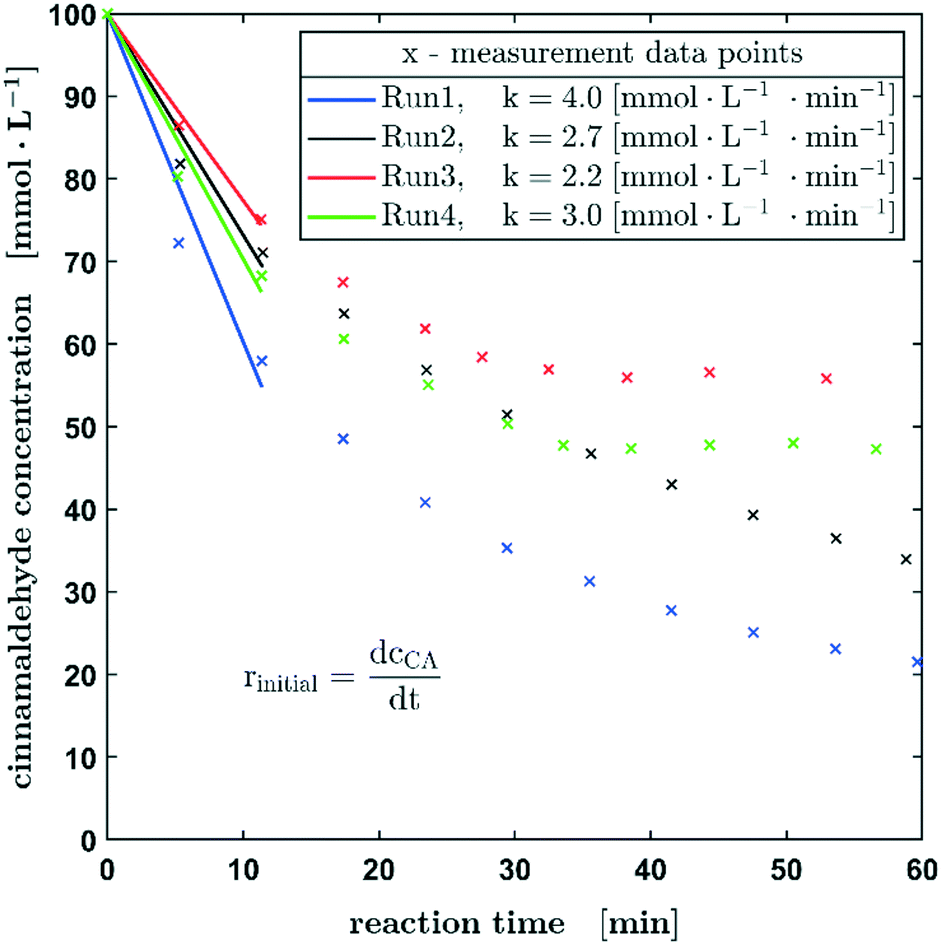 | ||
| Fig. 7 Reproducibility experiments of the hydrogenation of cinnamaldehyde. Reaction conditions: p0 = 1 MPa, c0 = 100 mmol L−1 (cinnamaldehyde in ethanol), 100% H2. An initial increase in the reaction rate can be observed. | ||
Fig. 8a shows the reaction rates for all four particle fractions in the hydrogenation of nitrobenzene and the reaction rates of the hydrogenation of cinnamaldehyde for two particle sizes. Since the catalyst was passed through by the slug twice, the substrate concentration was determined before the first contact and after the second. This method of operation allows a quick screening of the catalysts. Besides the lowest grain size, the reaction rate decreased with an increasing particle fraction for the hydrogenation of nitrobenzene.
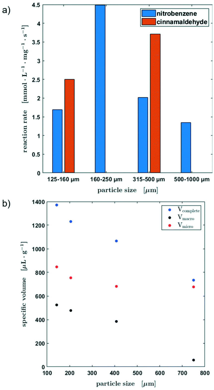 | ||
| Fig. 8 (a) Specific pore volumes of the different pore sizes of the original activated carbon material. (b) Initial reaction rate of the hydrogenation of nitrobenzene and cinnamaldehyde depending on the catalyst particle size. | ||
To explain these experimental observations in more detail, the pore volumes of the different catalyst particle sizes were determined from centrifugation experiments (Fig. 8b, for further information see the ESI,† section S4). It becomes obvious, that there is a clear decrease of the macropore volume when the particle size is increased. The smaller the particle size, the greater the influence of the smallest pores, in which mass transfer limitations become more probable. Therefore, an ideal mixing during the contact time could not be assumed. Table S1 in section S4 of the ESI† shows an estimation of the diffusion time as a function of the particle radius. However, the smallest catalyst particle fraction showed an unusual behavior, which might be attributed to the enhanced number of micro pores leading to limitations in the liquid exchange with the slug as well as a larger liquid was held up due to capillary forces between the particles.
Consequently, the usability of the reactor concept for kinetic studies is limited by the particle size of the catalyst and a compromise must be found between the maximum and minimum particle size in order to avoid mass transport limitations on the one hand and the non-ideal liquid mixing during the contact time on the other hand. Since only two data points are available for the hydrogenation of cinnamaldehyde, no further conclusions can be drawn about the influence of the particle fraction on the kinetic behaviour at this point.
Conclusions
The proof-of-concept for a 3-phase oscillating droplet reactor concept for kinetic investigations regarding three phase reactions was proven as a part of this study. Based on the hydrogenation of nitrobenzene and cinnamaldehyde, the implementation of a non-porous fibre Pd/C catalyst and a porous fixed bed Pd/C catalyst was investigated.Experiments on the Pd/C fibre catalyst could be carried out at different hydrogen pressures under very good reproducibility. This gives the possibility to investigate the performance of various metals supported on carbon in certain catalytic reactions. This element-screening could also be interesting with respect to catalytic wall-coating reactors.
Experiments concerning the fixed bed catalyst bed could be carried out with the aid of a 3D-printed catalyst holder, which was developed as a part of this project. In this context also the influence of the catalyst particle size on the hydrogenation reactions rates was investigated. As it was expected, smaller particles showed higher reaction rates, since mass transport limitations are more prone to affect bigger particles. The investigations revealed that the reactor concept cannot be applied to particles, which fall below a certain size, because an ideal liquid exchange during the slug/catalyst contact time cannot be assumed due to an increased number of micro pores. To be able to examine catalyst bulk materials of different particle sizes in the best possible way in the future, the catalyst holder could be adapted. Hereby the aim is to alter the holder individually via 3D printing to ensure a constant ratio of the inner diameter to particle size. Despite this limitation, kinetic data of reasonable quality could be obtained using the oscillating droplet reactor setup even for bigger catalyst particles. To perform experiments under higher pressure, two points must be addressed. Firstly, the geometry of the catalyst holder must be adjusted with respect to its diameter. A reduction in the diameter will also reduce bypass flows of hydrogen, which can lead to droplet deformation and breaking. The second point is an appropriate sealing also with respect to gas permeation through the polymer-based parts. More hydrogen tight materials, such as high-density polyethylene or poly vinyl chloride might be better alternatives. To perform oscillation experiments at even higher pressures, stainless steel equipment or pressure tight quartz flow cells might be applicable.
Also, our investigations have shown that the 3-phase oscillating droplet reactor is an interesting tool for the kinetic investigation of slow reactions. In this case the gas consumption per time interval is decreased, so that the reaction should not be limited by gas diffusion. Furthermore, due to the slower reaction, full conversion on the catalyst bed between two oscillation cycles can be avoided, so that the interpolation procedure to determine the reactant concentration can be simplified. Alternatively, the concentrations of the reactants (substrate and/or hydrogen), the contact time of the slug with the catalyst or the activity of the catalyst could be reduced to achieve a similar effect.
Overall, the 3-phase oscillating droplet reactor can be employed as a valuable tool for obtaining kinetic reaction data of hydrogenation reactions using 2D and 3D metal catalysts. Obviously, the investigation of a wide array of chemical reactions and various catalyst sets is needed to demonstrate a wide applicability of the setup. However, we think that the examples shown here already indicate that this setup might be a very valuable tool to understand and develop catalytic reactions and processes.
Conflicts of interest
There are no conflicts to declare.Acknowledgements
We greatly acknowledge funding through BASF SE and hte GmbH. Part of this work was funded by the German Federal Ministry of Research (BMBF) as a part of the Innovation Partnership M2Aind, project 13FH8I01IA within the framework “Starke Fachhochschulen – Impuls für die Region” (FH-Impuls).Notes and references
- Handbook Of Heterogeneous Catalysis, ed. G. Ertl, H. Knözinger, F. Schüth and J. WeitkampWiley-VCH, 1st edn, 2009 Search PubMed.
- M. Baerns, A. Behr, A. Brehm, J. Gmehling, K.-O. Hinrichsen, H. Hofmann, R. Palkovits, U. Onken and A. Renken, Technische Chemie, Wiley-VCH, Weinheim, 2013 Search PubMed.
- J. A. Moulijn, J. Pérez-Ramírez, R. J. Berger, G. Hamminga, G. Mul and F. Kapteijn, Catal. Today, 2003, 81, 457–471 CrossRef CAS.
- A. Sundermann, M. Kögel and O. Gerlach, Catalysts, 2019, 9, 776 CrossRef CAS.
- A. Sundermann and O. Gerlach, Catalysts, 2016, 6, 23 CrossRef.
- S. Titlbach, C. Futter, M. Lejkowski, A. L. de Oliveira and S. A. Schunk, Chem. Ing. Tech., 2014, 86, 1013–1028 CrossRef CAS.
- A. Gordillo, S. Titlbach, C. Futter, M. L. Lejkowski, E. Prasetyo, L. T. A. Rupflin, T. Emmert and S. A. Schunk, in Ullmann's Encyclopedia of Industrial Chemistry, Wiley-VCH Verlag GmbH & Co. KGaA, Weinheim, Germany, 2014, pp. 1–19 Search PubMed.
- C. Spadoni, R. V. Jones, L. Urge and F. Darvas, Chemistry Today, 2006, 38–41 Search PubMed.
- G. Szöllosi, B. Hermán, F. Fülöp and M. Bartók, React. Kinet. Catal. Lett., 2006, 88, 391–398 CrossRef.
- P. Watts and C. Wiles, Chem. Commun., 2007, 443–467 RSC.
- K. Schubert, J. Brandner, M. Fichtner, G. Linder, U. Schygulla and A. Wenka, Microscale Thermophys. Eng., 2001, 5, 17–39 CrossRef CAS.
- T. Bauer, S. Haase and R. Lange, Chem. Ing. Tech., 2009, 81, 989–994 CrossRef CAS.
- J. Baek, Y. Shen, I. Lignos, M. G. Bawendi and K. F. Jensen, Angew. Chem., Int. Ed., 2018, 57, 10915–10918 CrossRef CAS PubMed.
- V. Sebastian, S. Basak and K. F. Jensen, AIChE J., 2016, 62, 373–380 CrossRef CAS.
- V. Sebastián, N. Zaborenko, L. Gu and K. F. Jensen, Cryst. Growth Des., 2017, 17, 2700–2710 CrossRef.
- D. M. Roberge, L. Ducry, N. Bieler, P. Cretton and B. Zimmermann, Chem. Eng. Technol., 2005, 28, 318–323 CrossRef CAS.
- M. Abolhasani, C. W. Coley and K. F. Jensen, Anal. Chem., 2015, 87, 11130–11136 CrossRef CAS PubMed.
- D. Liu, G. Liang, X. Lei, B. Chen, W. Wang and X. Zhou, Anal. Chim. Acta, 2012, 718, 58–63 CrossRef CAS PubMed.
- Y. J. Hwang, C. W. Coley, M. Abolhasani, A. L. Marzinzik, G. Koch, C. Spanka, H. Lehmann and K. F. Jensen, Chem. Commun., 2017, 53, 6649–6652 RSC.
- T. Klement, N. Kockmann and T. Röder, Chem. Ing. Tech., 2019, 91, 651–656 CrossRef CAS.
- T. Klement, N. Kockmann, C. Schwede and T. Röder, Ind. Eng. Chem. Res. DOI:10.1021/acs.iecr.0c04732.
- M. Abolhasani, C. W. Coley, L. Xie, O. Chen, M. G. Bawendi and K. F. Jensen, Chem. Mater., 2015, 27, 6131–6138 CrossRef CAS.
- S. Duraiswamy and S. A. Khan, Small, 2009, 5, 2828–2834 CrossRef CAS PubMed.
- P. Löser, S. Hanf, F. Wolff, T. Röder, T. Klement, M. Dejmek and S. A. Schunk, EP Pat., 20155472.2, Vorrichtung und Verfahren zur Untersuchung von Drei-Phasen-Reaktionen, 2020 Search PubMed.
- M. N. Kashid and D. W. Agar, Chem. Eng. J., 2007, 131, 1–13 CrossRef CAS.
- M. Turáková, T. Salmi, K. Eränen, J. Wärnå, D. Y. Murzin and M. Králik, Appl. Catal., A, 2015, 499, 66–76 CrossRef.
- E. B. Hemming, A. F. Masters and T. Maschmeyer, Chem. – Eur. J., 2020, 26, 7059–7064 CrossRef CAS PubMed.
- V. R. Choudhary, M. G. Sane and H. G. Vadgaonkar, J. Chem. Eng. Data, 1986, 31, 294–296 CrossRef CAS.
- S. Haase, T. Bauer, G. Hilpmann, M. Lange, M.-M. Ayubi and R. Abiev, Theor. Found. Chem. Eng., 2020, 54, 48–63 CrossRef CAS.
Footnotes |
| † Electronic supplementary information (ESI) available: Synthetic methods, material characterisation, and data evaluation methods. See DOI: 10.1039/d0re00466a |
| ‡ Shared first co-authorship. |
| This journal is © The Royal Society of Chemistry 2021 |