Simultaneous CO2 capture and heat storage by a Ca/Mg-based composite in coupling calcium looping and CaO/Ca(OH)2 cycles using air as a heat transfer fluid
Chunxiao
Zhang
a,
Yingjie
Li
 *a,
Yi
Yuan
a,
Zeyan
Wang
 b,
Tao
Wang
c and
Wentao
Lei
c
aSchool of Energy and Power Engineering, Shandong University, Jinan, Shandong 250061, China. E-mail: liyj@sdu.edu.cn
bState Key Laboratory of Crystal Materials, Shandong University, Jinan 250100, China
cShandong Naxin Electric Power Technology Co., Ltd., Jinan 250101, China
First published on 29th September 2020
Abstract
The simultaneous CO2 capture and heat storage performances of the Ca/Mg-based composite prepared from carbide slag and dolomite in a process coupling calcium looping and CaO/Ca(OH)2 heat storage using air as a heat transfer fluid were investigated. In the coupling process, the spent CaO-based material experiencing multiple CO2 capture cycles was employed in the CaO/Ca(OH)2 heat storage process, and then the cycled material was again used to capture CO2. When the mass ratio of CaO/MgO in the composite is 90![[thin space (1/6-em)]](https://www.rsc.org/images/entities/char_2009.gif) :
:![[thin space (1/6-em)]](https://www.rsc.org/images/entities/char_2009.gif) 10, it exhibits the highest heat storage capacity of 0.53 mol mol−1 and a heat storage density of 0.90 GJ t−1 after 30 heat storage cycles. The adverse effect of CO2 in air as the heat transfer fluid on CaO/Ca(OH)2 heat storage capacity is overcome by the introduction of calcium looping cycles. By introducing a calcium looping cycle after the 10th and 20th heat storage cycles, the subsequent heat storage capacities of the composite are improved by 31% and 57%, respectively. The CO2 capture reactivity of the composite is also promoted by the introduction of heat storage cycles. Therefore, the simultaneous efficient CO2 capture and heat storage using the Ca/Mg-based composite is achieved in the process coupling calcium looping and CaO/Ca(OH)2 cycles.
10, it exhibits the highest heat storage capacity of 0.53 mol mol−1 and a heat storage density of 0.90 GJ t−1 after 30 heat storage cycles. The adverse effect of CO2 in air as the heat transfer fluid on CaO/Ca(OH)2 heat storage capacity is overcome by the introduction of calcium looping cycles. By introducing a calcium looping cycle after the 10th and 20th heat storage cycles, the subsequent heat storage capacities of the composite are improved by 31% and 57%, respectively. The CO2 capture reactivity of the composite is also promoted by the introduction of heat storage cycles. Therefore, the simultaneous efficient CO2 capture and heat storage using the Ca/Mg-based composite is achieved in the process coupling calcium looping and CaO/Ca(OH)2 cycles.
1. Introduction
CO2 emission from fossil fuel-fired power plants as an important part of anthropogenic greenhouse gas emissions has a major impact on global warming and climate change.1,2 CO2 capture and storage (CCS) is considered an efficient solution to solve this problem.3–5 Calcium looping (CaL), i.e. the repetitive carbonation/calcination cycles of CaO, is a promising post-combustion CO2 capture technology for removing CO2 from fuel gas in coal-fired power plants.6–8 The carbonation and calcination of CaL are shown by eqn (1).9| CaO(s) + CO2(g) ↔ CaCO3(s) | (1) |
![[thin space (1/6-em)]](https://www.rsc.org/images/entities/char_2009.gif) 27 and CeO2
27 and CeO2![[thin space (1/6-em)]](https://www.rsc.org/images/entities/char_2009.gif) 28 efficiently enhances the sintering resistance of CaO during CO2 capture cycles. Al2O3 and SiO2 react with CaO to consume the active component CaO and decrease the active CaO content in the composite. MgO as a supporter does not react with CaO to consume CaO and it is cheaper than ZrO2, TiO2, La2O3 and CeO2, making it a potential supporter of CaO. MgO appears as a promising supporter for CaO in the CaL process. Park et al.29 reported a CaO–MgO material prepared by the co-precipitation method with excellent cyclic stability. Hu et al.30 employed waste sludge to mix with limestone to enhance the CO2 capture performance, and confirmed that the inert support MgO in sludge acts as the metal framework to improve the resistance to sintering of the sorbent. Naeem et al.31 proposed that a sintering-induced capacity decay of MgO-supported CaO could be overcome via a resorcinol/formaldehyde carbon-gel templating approach using 20 mol% of Mg2+ for stabilization. Valverde et al.32 demonstrated that a CaO-based material derived from dolomite had greater CO2 capture capacity than limestone, as a result of the good support of MgO.
28 efficiently enhances the sintering resistance of CaO during CO2 capture cycles. Al2O3 and SiO2 react with CaO to consume the active component CaO and decrease the active CaO content in the composite. MgO as a supporter does not react with CaO to consume CaO and it is cheaper than ZrO2, TiO2, La2O3 and CeO2, making it a potential supporter of CaO. MgO appears as a promising supporter for CaO in the CaL process. Park et al.29 reported a CaO–MgO material prepared by the co-precipitation method with excellent cyclic stability. Hu et al.30 employed waste sludge to mix with limestone to enhance the CO2 capture performance, and confirmed that the inert support MgO in sludge acts as the metal framework to improve the resistance to sintering of the sorbent. Naeem et al.31 proposed that a sintering-induced capacity decay of MgO-supported CaO could be overcome via a resorcinol/formaldehyde carbon-gel templating approach using 20 mol% of Mg2+ for stabilization. Valverde et al.32 demonstrated that a CaO-based material derived from dolomite had greater CO2 capture capacity than limestone, as a result of the good support of MgO.
CaO-Based materials are also used in the CaO/Ca(OH)2 thermochemical heat storage (THS) process, i.e. the reversible hydration/dehydration cycles of CaO. The hydration and dehydration of CaO/Ca(OH)2 THS are shown by eqn (2).33
| Ca(OH)2(s) ↔ CaO(s) + H2O(g) ΔH = ±104 kJ mol−1 | (2) |
Related theoretical and experimental research studies focused on the CaO/Ca(OH)2 THS system have been reported.37 Schaube et al.38 investigated the thermal behavior of a CaO/Ca(OH)2 THS reactor with direct heat transfer, and pointed out that the particle reaction rate was the main limitation parameter instead of the heat transfer and mass transport. Schmidt et al.39 designed a reactor for about 20 kg Ca(OH)2 to study the charge and discharge properties of the reactor and they found that the storage materials maintained stable properties and did not show an obvious degradation after 10 cycles. Lin et al.40 measured the reaction rates over 20 hydration/dehydration cycles, and found that CaO was completely converted to Ca(OH)2 although the CaO hydration rate decreased with the cycle number. Our previous research demonstrated that the deactivated carbide slag experiencing multiple CaL cycles for CO2 capture could be used in the CaO/Ca(OH)2 THS process.41 These experimental results demonstrated the possibility of applying CaO/Ca(OH)2 THS on a technically relevant scale. However, severe fragmentation and agglomeration of particles during repetitive hydration/dehydration cycles restrain the mass transfer and thermal conductivity, which is detrimental to the heat storage.42 To solve this problem, some additives have been proposed as supporters to enhance the mechanical and chemical stability of CaO-based materials in CaO/Ca(OH)2 THS cycles.43 Roßkopf et al.44 confirmed that the addition of nanoparticles of SiO2 could prevent the growth and formation of large agglomerates in a CaO-based material and improve its cyclic stability and heat storage capacity during CaO/Ca(OH)2 THS. Al2O3 as a supporter was used to enhance the material structural integrity of CaO.45 Mejia et al.46 demonstrated that Ca(OH)2 granules coated with Al2O3 nanostructured particles maintained a stable spherical shape after several hydration/dehydration cycles. Afflerbach et al.47 proposed that the aggregation in a CaO-based material was alleviated by encapsulation with a vermiculite material in CaO/Ca(OH)2 THS cycles. MgO has been proposed as an inert support that could improve the sintering resistance of CaO-based materials in CO2 capture cycles. However, the effect of MgO on the CaO/Ca(OH)2 THS performance of CaO-based materials requires further experimental investigation.
The inert gas, e.g. N2 is commonly supplied as a heat transfer fluid to maintain the stable reactivity of THS materials.42 However, the separation of N2 from air increases the operating cost and energy consumption. Edwards et al.48 proposed the use of a calcium looping based process as a thermal storage and transportation system for concentrated solar power plants. They proposed using an air stream as a heat transfer fluid in a CaL heat storage system, where the heat released from the carbonation of CaO was transferred to an air flow which powered a Brayton cycle to produce electricity. However, they did not investigate the use of air as the heat transfer fluid in a CaO/Ca(OH)2 THS system. Air instead of N2 as the heat transfer fluid in the CaO/Ca(OH)2 THS system is cheaper and more convenient. However, Yan et al.49 found that CO2 in air reduced the cyclic stability of CaO-based materials in CaO/Ca(OH)2 THS cycles, because above 5% of CaO was converted into CaCO3 in the hydration stage, which did not decompose during the dehydration stage. The bad influence of CO2 in air on the THS performance of CaO increased markedly with the number of THS cycles. To reduce the adverse effect of CO2 in air as the heat transfer fluid, Linder et al.36 investigated thermochemical energy storage based on CaO/Ca(OH)2 in a kW-scale reactor system, where a CO2-adsorption drier was adopted to reduce CO2 content in compressed air. However, this causes additional cost and operational complexity, hindering the industrial application of CaO/Ca(OH)2 THS.
To reuse the spent CaO exhausted from CaL cycles, Yuan et al.41 proposed a process coupling CaL for CO2 capture and CaO/Ca(OH)2 THS for a coal-fired power plant. They employed the carbide slag experiencing multiple CaL cycles as a heat storage material in the CaO/Ca(OH)2 THS process to heat the feed water of the coal-fired boiler and found that the cycled carbide slag was still suitable to be used in the CaO/Ca(OH)2 THS process where N2 acted as the heat transfer fluid. However, the CaO-based material exhausted from CaO/Ca(OH)2 THS cycles was not used to capture CO2 in the CaL process. Thus, they only investigated the THS performance of the CaO-based material experiencing CaL cycles, but the CO2 capture performance of the CaO-based material from CaO/Ca(OH)2 THS cycles was not studied.41 Sun et al.50 proposed the application of CaO derived from calcium acetate (Ac-CaO) to a system coupling CO2 capture and CaO/Ca(OH)2 THS using N2 as a heat transfer fluid, where the cycled CaO-based material experiencing THS cycles was again sent to the CaL process for CO2 capture, which was different from the coupling process proposed by Yuan et al.41 Sun et al.50 found that the THS performance of Ac-CaO stored under an air atmosphere decayed with the THS cycles, because of the formation of CaCO3 (0.038 vol% CO2 in air), but it was still higher than that of calcined limestone. In addition, they pointed out that the THS performance of Ac-CaO was enhanced by the CaL process because of the decomposition of CaCO3 in the calcination of CaL.
Carbide slag as a calcium-based industrial waste could be employed in CaO/Ca(OH)2 THS. However, it was found that the heat storage capacity of carbide slag decreased with the number of THS cycles.41 Dolomite is mainly composed of CaO and MgO, and MgO is a good support to improve the CO2 capture capacity of CaO in the CaL process as abovementioned. Yan et al.51 prepared a CaO/MgO material from carbide slag and dolomite for CO2 capture and found that the CO2 capture capacity of the sorbent with the mass ratio of CaO/MgO = 90![[thin space (1/6-em)]](https://www.rsc.org/images/entities/char_2009.gif) :
:![[thin space (1/6-em)]](https://www.rsc.org/images/entities/char_2009.gif) 10 was as high as 0.52 g g−1 after 10 CaL cycles. However, they did not study the heat storage performance of the CaO/MgO material in CaO/Ca(OH)2 THS cycles.
10 was as high as 0.52 g g−1 after 10 CaL cycles. However, they did not study the heat storage performance of the CaO/MgO material in CaO/Ca(OH)2 THS cycles.
In this work, to achieve simultaneous efficient CO2 capture and heat storage, a Ca/Mg-based composite prepared from carbide slag and dolomite was employed in the coupling CaL and CaO/Ca(OH)2 THS process, where air acts as the heat transfer fluid instead of N2. The schematic diagram of the coupling process is presented in Fig. 1. The generated CaCO3 from the reaction of CO2 in air and CaO during the THS cycles is probably regenerated to CaO again in the calciner of CaL due to the high temperature. Thus, the adverse effect of air as the heat transfer fluid is eliminated in the coupling CaL and THS process. As illustrated in Fig. 1, the coupling CaL and THS process is schematically described as follows: CO2 from the flue gas of the coal-fired power plant is captured in the carbonator by the CaO-based material in the CaL process. The CaO-based material experiencing multiple CO2 capture cycles which is exhausted from the calciner is transported to the hydrator by air as the heat transfer fluid and reacts with steam to form Ca(OH)2 and release heat to heat the feed water of the coal-fired boiler. Then the formed Ca(OH)2 is sent to the dehydrator heated by solar energy to regenerate CaO. After multiple CaO/Ca(OH)2 THS cycles, a part of the CaO-based material from the dehydrator is again fed into the carbonator and the calciner for cyclic CO2 capture and the excess CaO is discharged from the dehydrator for the production of cement. The CaCO3 in the CaO-based material formed in the THS process can be converted to CaO in the calciner. The simultaneous CO2 capture and heat storage performances of the Ca/Mg-based composite in the coupling process were investigated. The heat storage capacity of the Ca/Mg-based composite after CaL cycles and the CO2 capture capacity of the composite after CaO/Ca(OH)2 THS cycles were discussed.
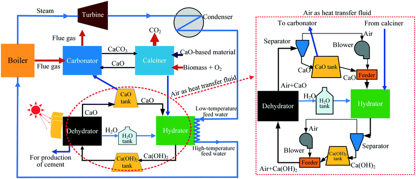 | ||
| Fig. 1 Schematic diagram of a process coupling CaL for CO2 capture and CaO/Ca(OH)2 THS for a coal-fired power plant. | ||
2. Experimental
2.1. Sample preparation
Carbide slag was sampled from a chlor-alkali plant in Shandong Province, China. Dolomite was obtained from Hebei Province, China. The chemical components of carbide slag and dolomite were analyzed by X-ray fluorescence (XRF), as shown in Table 1. The carbide slag and dolomite were ground and sieved to a size less than 0.125 mm.| Component | CaO | MgO | Al2O3 | SiO2 | Fe2O3 | K2O | TiO2 | SrO | Others | Loss in ignition |
|---|---|---|---|---|---|---|---|---|---|---|
| Carbide slag | 70.96 | — | 2.15 | 1.87 | 0.22 | 0.14 | 0.06 | 0.01 | 0.04 | 24.55 |
| Dolomite | 33.32 | 19.13 | 0.08 | 0.28 | 0.20 | 0.02 | — | — | 0.01 | 46.96 |
The preparation procedure of the Ca/Mg-based composite is illustrated in Fig. 2. Firstly, 10 g of calcined carbide slag and an appropriate amount of calcined dolomite were added into 50 ml of distilled water in a beaker at room temperature. The mass ratio of CaO to MgO in the composite was specified as 95![[thin space (1/6-em)]](https://www.rsc.org/images/entities/char_2009.gif) :
:![[thin space (1/6-em)]](https://www.rsc.org/images/entities/char_2009.gif) 5, 90
5, 90![[thin space (1/6-em)]](https://www.rsc.org/images/entities/char_2009.gif) :
:![[thin space (1/6-em)]](https://www.rsc.org/images/entities/char_2009.gif) 10 and 80
10 and 80![[thin space (1/6-em)]](https://www.rsc.org/images/entities/char_2009.gif) :
:![[thin space (1/6-em)]](https://www.rsc.org/images/entities/char_2009.gif) 20, so the mass ratio of calcined carbide slag to calcined dolomite was determined. Secondly, 50 ml of glycerin were poured into the abovementioned beaker with mechanical stirring at room temperature. Thirdly, the mixture was stirred at 60 °C in a water bath for 60 min to form the dispersed solution. Then, the dispersed solution was sent to a muffle furnace at 850 °C under an air atmosphere for 60 min and then the Ca/Mg-based composite was obtained. The composite was ground and sieved to size <0.125 mm. The Ca/Mg-based composite was denoted as CxMy, where x and y represent the mass fractions of CaO and MgO in the composite, respectively. For example, C95M5 denotes the mass ratio of CaO to MgO of 95
20, so the mass ratio of calcined carbide slag to calcined dolomite was determined. Secondly, 50 ml of glycerin were poured into the abovementioned beaker with mechanical stirring at room temperature. Thirdly, the mixture was stirred at 60 °C in a water bath for 60 min to form the dispersed solution. Then, the dispersed solution was sent to a muffle furnace at 850 °C under an air atmosphere for 60 min and then the Ca/Mg-based composite was obtained. The composite was ground and sieved to size <0.125 mm. The Ca/Mg-based composite was denoted as CxMy, where x and y represent the mass fractions of CaO and MgO in the composite, respectively. For example, C95M5 denotes the mass ratio of CaO to MgO of 95![[thin space (1/6-em)]](https://www.rsc.org/images/entities/char_2009.gif) :
:![[thin space (1/6-em)]](https://www.rsc.org/images/entities/char_2009.gif) 5 in the composite.
5 in the composite.
2.2. CO2 capture and heat storage tests in the process coupling CaL and THS
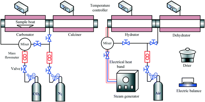
The CO2 capture and heat storage tests of the samples in the process coupling CaL and THS were performed in a fixed-bed reactor system, including a carbonator, a calciner, a hydrator and a dehydrator, as shown in Fig. 3. The CO2 capture tests of the samples such as Ca/Mg-based composites, carbide slag and dolomite after the CaL cycles for CO2 capture were performed in the carbonator and the calciner. 500 mg of sample in a porcelain boat was sent to the carbonator at 700 °C under a 15 vol% CO2/85 vol% N2 atmosphere for 20 min. The flow rates of CO2 and N2 from the gas cylinders entering the reactors were controlled by mass flow meters (Sevenstar D08-3E) and the total flow rate of the gas mixture was 2 L min−1. Then the carbonated sample was sent to the calciner at 850 °C under N2 for 10 min. After each carbonation/calcination step, the sample was cooled to room temperature in an air drier, and then was weighed using a delicate electronic balance (Mettler Toledo-XS105DU). Subsequently, the sample was sent to the carbonator for a next CaL cycle. The carbonation conversion was used to describe the CO2 capture capacity of the sample during CaL cycles, which was calculated as follows: | (3) |
The THS cycles of the sample were carried out in the hydrator and the dehydrator. Air was employed as the heat transfer fluid and the steam (200 °C) from the steam generator (Huaxiangstar HSG20) was mixed with air before entering the hydrator. The total flow rate of the gas mixture entering the reactors was controlled to 2 L min−1 by the mass flow meter. The sample was fed into the hydrator at 400 °C under a 95 vol% steam/5 vol% air atmosphere for 5 min. Then, the hydrated sample from the hydrator was sent to the dehydrator at 550 °C under an air atmosphere for 10 min. Then, one hydration/dehydration cycle was finished. The sample after each hydration and dehydration was cooled in the air drier until room temperature and then weighed using the electronic balance. The hydration conversion and heat storage density were used to describe the heat storage capacity of the sample during THS cycles, which were respectively calculated as follows:
 | (4) |
 | (5) |
According to the above procedures, the heat storage test of the composite using N2 as the heat transfer fluid was carried out, to compare with that using air as the heat transfer fluid. Noticeably, the sample after each hydration/dehydration step was cooled in a drier filled with N2 instead of the air drier until room temperature when N2 acted as the heat transfer fluid. To determine the interaction between CaL and THS on the reaction performance of the Ca/Mg-based composite, the heat storage test of the composite experiencing CaL cycles and the CO2 capture test of the composite experiencing THS cycles were respectively carried out in the fixed-bed reactor system. In addition, heat storage and CO2 capture tests of the composites after a series of CaL and THS cycles were done. The experimental runs are shown in Table 2.
| Run no. | CaL and THS cycles | CaL conditions | THS conditions |
|---|---|---|---|
| Note: A denotes the CaL conditions: carbonation at 700 °C in 15% CO2/85% N2 for 20 min and calcination at 850 °C in N2 for 10 min; B represents the THS conditions: hydration at 400 °C in 95% steam/5% N2 for 5 min and dehydration at 550 °C in N2 for 10 min; C denotes the THS conditions: hydration at 400 °C in 95% steam/5% air for 5 min and dehydration at 550 °C in air for 10 min. | |||
| 1 | 30 THS cycles | A | B |
| 2 | 30 THS cycles | A | C |
| 3 | 20 CaL cycles | A | C |
| 4 | 10 CaL and 30 THS cycles in sequence | A | C |
| 5 | 10 CaL, 30 THS, 1 CaL and 1 THS cycles in sequence | A | C |
| 6 | 10 THS, 1 CaL, 10 THS, 1 CaL and 10 THS cycles in sequence | A | C |
| 7 | 10 CaL, 10 THS, 5 CaL, 10 THS and 5 CaL cycles in sequence | A | C |
2.3. Characterization
The functional groups of samples were analyzed using an attenuated total reflectance-Fourier transform infrared spectrometer (FT-IR, Vertex70). The morphologies of samples after CaL and THS cycles were observed with a SUPRATM 55 scanning electron microscope (SEM). A Micromeritics ASAP 2020-M nitrogen adsorption analyzer was used to evaluate the pore volumes and pore size distributions of the samples after CaL and THS cycles by the Barrett–Joyner–Halenda (BJH) model. The element distributions on the surface of the samples were detected using an Oxford INCA X-sight energy dispersive X-ray (EDX) spectrometer.3. Results and discussion
3.1. Heat storage capacity of the Ca/Mg-based composite in THS cycles
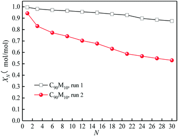
The heat storage performances of the Ca/Mg-based composite using different heat transfer fluids such as air and N2 are compared. As presented in Fig. 4, as the cycle number increases from 1 to 30, the hydration conversion of C90M10 during 30 THS cycles using N2 as the heat transfer fluid (run 1) decreases slowly, while that using air as the heat transfer fluid (run 2) decays sharply. The aggregation of CaO occurs during the THS cycles, which decreases the hydration rate of CaO.40 In addition, the XN of C90M10 after run 2 is much lower than that after run 1, which is attributed to the bad effect of CO2 in air on hydration of CaO.49 The X30 of C90M10 after run 2 is 0.53 mol mol−1, which is 40% lower than that after run 1. It indicates that using air as the heat transfer fluid decreases the heat storage capacity and cyclic stability of the CaO-based material. However, air is significantly cheaper than N2. In the following research, the effect of CO2 in air on the heat storage performance of Ca/Mg-based composites in the coupling CaL and THS process using air as the heat transfer fluid of THS is investigated.The heat storage performance of Ca/Mg-based composites during 30 THS cycles (run 2) is illustrated in Fig. 5. As shown in Fig. 5(a), the hydration conversions of the composites, carbide slag and dolomite decrease with the number of THS cycles. The XN of the composites are slightly lower than that of carbide slag in the previous several THS cycles, but they exhibit higher XN than carbide slag and dolomite with the further increase of the cycle number. When the mass ratio of CaO to MgO is 90![[thin space (1/6-em)]](https://www.rsc.org/images/entities/char_2009.gif) :
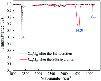
:![[thin space (1/6-em)]](https://www.rsc.org/images/entities/char_2009.gif) 10, the composite shows the highest hydration conversion during 30 THS cycles. The addition of MgO probably restrains the aggregation of CaO and provides a good support for CaO, which is beneficial for the hydration of CaO in the composite. However, too much MgO impedes the diffusion of steam in the composite, which has an adverse effect on the hydration of CaO. Thus, C90M10 shows the superior hydration conversion during multiple THS cycles. The X30 of C90M10 is 29% and 48% higher than those of carbide slag and dolomite, respectively. As the number of THS cycles increases from 1 to 30, the hydration conversions of carbide slag and C90M10 drop by 60% and 41%, respectively. It indicates that C90M10 possesses higher cyclic stability than carbide slag during the THS cycles due to the presence of MgO in the composite. As shown in Fig. 5(b), C90M10 exhibits a higher heat storage density than the other composites during multiple THS cycles. The D15 and D30 of C90M10 are 1.14 and 0.90 GJ t−1, which are 23% and 26% higher than those of carbide slag, respectively. The FT-IR spectra of C90M10 after the 1st and 30th hydrations are shown in Fig. 6. The peak located at 3641 cm−1 is associated with the stretching vibration of the O–H bond in Ca(OH)2. The peaks located at 1420 and 875 cm−1 are associated with the anti-symmetric stretching vibration and out-of-plane bending vibration of the CO32− bond, respectively. Only the strong O–H bond peak exists in the spectrum of C90M10 after the 1st hydration and the CO32− bond peak is not found. This means the effect of CO2 in air on the heat storage of C90M10 is little in the 1st THS cycle. However, the O–H and CO32− bond peaks both exist in the spectrum of C90M10 after the 30th hydration. It indicates that CaCO3 is obviously formed in C90M10 after 30 THS cycles, which is attributed to the carbonation reaction between CO2 in air (0.038 vol%) and CaO. The maximum carbonation temperatures of CaO in the hydration and dehydration stages under different conditions can be computed according to eqn (6),52 which are 448 and 533 °C, respectively.
10, the composite shows the highest hydration conversion during 30 THS cycles. The addition of MgO probably restrains the aggregation of CaO and provides a good support for CaO, which is beneficial for the hydration of CaO in the composite. However, too much MgO impedes the diffusion of steam in the composite, which has an adverse effect on the hydration of CaO. Thus, C90M10 shows the superior hydration conversion during multiple THS cycles. The X30 of C90M10 is 29% and 48% higher than those of carbide slag and dolomite, respectively. As the number of THS cycles increases from 1 to 30, the hydration conversions of carbide slag and C90M10 drop by 60% and 41%, respectively. It indicates that C90M10 possesses higher cyclic stability than carbide slag during the THS cycles due to the presence of MgO in the composite. As shown in Fig. 5(b), C90M10 exhibits a higher heat storage density than the other composites during multiple THS cycles. The D15 and D30 of C90M10 are 1.14 and 0.90 GJ t−1, which are 23% and 26% higher than those of carbide slag, respectively. The FT-IR spectra of C90M10 after the 1st and 30th hydrations are shown in Fig. 6. The peak located at 3641 cm−1 is associated with the stretching vibration of the O–H bond in Ca(OH)2. The peaks located at 1420 and 875 cm−1 are associated with the anti-symmetric stretching vibration and out-of-plane bending vibration of the CO32− bond, respectively. Only the strong O–H bond peak exists in the spectrum of C90M10 after the 1st hydration and the CO32− bond peak is not found. This means the effect of CO2 in air on the heat storage of C90M10 is little in the 1st THS cycle. However, the O–H and CO32− bond peaks both exist in the spectrum of C90M10 after the 30th hydration. It indicates that CaCO3 is obviously formed in C90M10 after 30 THS cycles, which is attributed to the carbonation reaction between CO2 in air (0.038 vol%) and CaO. The maximum carbonation temperatures of CaO in the hydration and dehydration stages under different conditions can be computed according to eqn (6),52 which are 448 and 533 °C, respectively.
 | (6) |
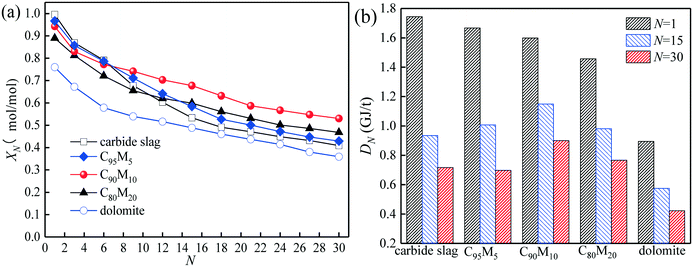 | ||
| Fig. 5 Heat storage capacities of Ca/Mg-based composites with different CaO/MgO mass ratios during 30 THS cycles (run 2): (a) hydration conversion, (b) heat storage density. | ||
3.2. Heat storage capacity of the Ca/Mg-based composite experiencing CaL cycles
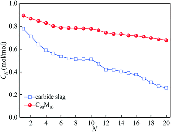
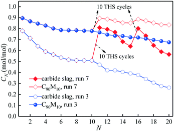
The CO2 capture performance of C90M10 during 20 CaL cycles (run 3) is depicted in Fig. 7. It is found that the CO2 capture capacity of C90M10 decreases more slowly with the number of CaL cycles than that of carbide slag, due to the higher sintering resistance of C90M10. As the cycle number is raised from 1 to 20, the CN of C90M10 only decays by 24%, while the CN of carbide slag decreases by 67%. The C20 of C90M10 is 2.3 times as high as that of carbide slag. It demonstrates that C90M10 possesses higher and more stable CO2 capture capacity than carbide slag during 20 CaL cycles.As shown in Fig. 8(a), the XN of C90M10 and carbide slag experiencing 10 CaL cycles during 30 THS cycles (run 4) decrease at different degrees with the number of THS cycles due to the aggregation and sintering of CaO and the negative effect of air as the heat transfer fluid. After the same THS cycles, the heat storage capacities of C90M10 and carbide slag experiencing 10 CaL cycles are lower than the original ones, respectively. The sintering of CaO experiencing 10 CaL cycles reduces its porosity and surface area, which increases the diffusion resistance of steam in the CaO-based materials. The X30 and D30 of C90M10 after run 4 are 0.47 mol mol−1 and 0.79 GJ t−1, respectively, which are only 12% lower than those after run 2. However, the X30 and D30 of carbide slag are 62% lower than those after run 2. It indicates that the CaL cycles have a slight effect on the heat storage capacity of C90M10, but they show obvious adverse effects on that of carbide slag. This is attributed to the higher sintering resistance of C90M10 during the CaL cycles. C90M10 exhibits higher heat storage capacity than carbide slag after run 4. The X30 and D30 of C90M10 after run 4 are 85% and 79% higher than those of carbide slag, respectively.
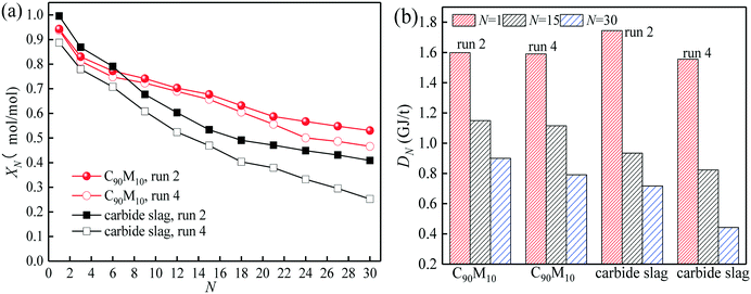 | ||
| Fig. 8 Heat storage capacity of C90M10 experiencing 10 CaL cycles during 30 THS cycles: (a) hydration conversion, (b) heat storage density. | ||
3.3. Effect of introduction of CaL cycles in THS cycles on heat storage capacity of the Ca/Mg-based composite
Fig. 9 presents the effect of the introduction of 1 CaL cycle in the THS process on the heat storage capacity of C90M10 experiencing 10 CaL cycles (run 5). After 30 THS cycles, the XN of C90M10 experiencing 10 CaL cycles decreases by 50%, as shown in Fig. 9. However, the X31 of C90M10 reaches 0.91, which is 94% higher than X30 and is almost the same as X1. It means that the introduction of the CaL cycle in the THS cycles significantly improves the heat storage capacity of C90M10. This is because the cumulative CaCO3 product layer after 30 THS cycles, which is formed by the reaction between CaO and CO2 in air, is converted into CaO in the calcination stage of CaL at high temperature. Therefore, the adverse effect of air as the heat transfer fluid is eliminated and the heat storage capacity of C90M10 is restored. Thus, the introduction of CaL cycles in the THS process significantly improves the heat storage capacity of C90M10 experiencing CaL cycles.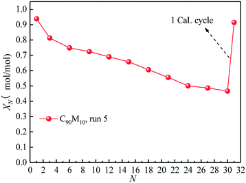 | ||
| Fig. 9 Effect of introduction of 1 CaL cycle in THS cycles on hydration conversion of C90M10 experiencing 10 CaL cycles. | ||
The comparison of the effects of introduction of CaL cycles in the THS process on the heat storage capacities of C90M10 and carbide slag after run 6 is shown in Fig. 10. As illustrated in Fig. 10(a), after the introduction of the 1st CaL cycle, the X11 of C90M10 and carbide slag after run 6 are 31% and 50% higher than those after run 2, respectively. After 20 THS cycles, the 2nd CaL cycle is introduced and the X21 of C90M10 and carbide slag after run 6 are 57% and 92% higher than those after run 2, respectively. Therefore, the introduction of the CaL cycles in the THS process exhibits a positive impact on the heat storage capacity of the two materials. In addition, the introduction of CaL cycles in the THS process has a greater improvement in the heat storage capacity of carbide slag, compared with C90M10. As illustrated in Fig. 10(b), the D30 of C90M10 and carbide slag after run 6 are 1.28 and 1.17 GJ t−1, which are 42% and 63% higher than those after run 2, respectively. In addition, the heat storage capacity of C90M10 is higher than that of carbide slag after run 6.
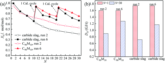 | ||
| Fig. 10 Effect of introduction of CaL cycles in THS cycles on heat storage capacity of C90M10: (a) hydration conversion, (b) heat storage density. | ||
3.4. Effect of introduction of THS cycles in CaL cycles on CO2 capture capacity of the Ca/Mg-based composite
Fig. 11 illustrates the effect of the introduction of THS cycles in 20 CaL cycles on the CO2 capture capacities of C90M10 and carbide slag after run 7. The two materials show a decay at different levels in CO2 capture capacity with the number of CaL cycles due to sintering. After 10 CaL cycles, the introduction of 10 THS cycles apparently improves the CO2 capture capacities of C90M10 and carbide slag. After the introduction of 10 THS cycles, the C11 of C90M10 and carbide slag after run 7 are 17% and 72% higher than those after run 3, respectively. After run 7, the C11 of C90M10 and carbide slag are even higher than their C1, respectively. As the number of CaL cycles further increases from 11 to 15, the CN of C90M10 and carbide slag after run 7 decay by 5% and 21%, respectively. Another 10 THS cycles are introduced after 15 CaL cycles and then the C16 of the two materials are again improved. The C20 of C90M10 and carbide slag after run 7 are 24% and 116% higher than those after run 3, respectively. It means that the CO2 capture activities of the two materials after the CaL cycles are adequately improved by the introduction of the THS cycles. This is because the repetitive hydration/dehydration cycles of the CaO-based material probably improve its pore structure, accelerating CO2 diffusion and adsorption in the material. Yin et al.53 also demonstrated that hydration could reactivate and regenerate the spent calcium-based sorbent, and its CO2 capture capacity could be recovered to more than 80%. The introduction of THS cycles in the CaL process shows a significantly higher improvement in the CO2 capture capacity of carbide slag, compared with C90M10. The C20 of C90M10 is 48% higher than that of carbide slag after run 7. Therefore, C90M10 still possesses a much higher cyclic CO2 capture capacity than carbide slag after the introduction of THS cycles in the CaL process. Considering both CO2 capture and heat storage, C90M10 seems promising in the coupling CaL and THS process.3.5. Microstructure analysis
The SEM images of C90M10 and carbide slag after different THS cycles (run 2) are illustrated in Fig. 12. As shown in Fig. 12(a) and (b), the surfaces of the original C90M10 and carbide slag are fluffy and porous, which are favorable for steam or CO2 diffusion into the materials. It should be noted that the original C90M10 has smaller grains and appears more porous compared with the original carbide slag, which results in higher CO2 capture capacity of C90M10. After 30 THS cycles, carbide slag exhibits more severe aggregation of CaO grains than C90M10, as presented in Fig. 12(c) and (d). Lots of pores in C90M10 and carbide slag after 30 THS cycles disappear, which is not beneficial for heat storage, but C90M10 still possesses more small pores than carbide slag. Therefore, although the heat storage capacities of C90M10 and carbide slag drop with the number of THS cycles, C90M10 exhibits higher cyclic heat storage capacity than carbide slag.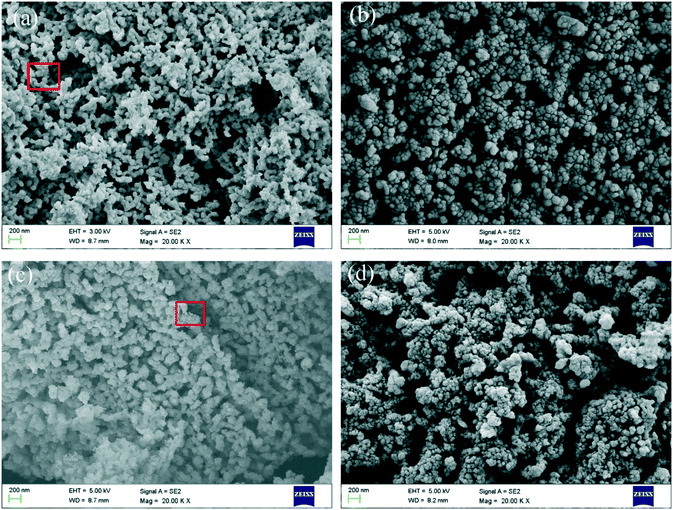 | ||
| Fig. 12 SEM images of C90M10 and carbide slag during THS cycles: (a) C90M10, (b) carbide slag, (c) C90M10 after 30 THS cycles (run 2), and (d) carbide slag after 30 THS cycles (run 2). | ||
SEM-EDX mapping of the marked regions in Fig. 12(a) and (c) are presented in Fig. 13(a) and (b), respectively. It is found that Ca, Mg and O elements are distributed on the surface of the original C90M10. According to the mass fractions of Ca and Mg in Fig. 13(a), the mass ratio of Ca/Mg in the marked region of C90M10 in Fig. 12(a) is approximately 11.1![[thin space (1/6-em)]](https://www.rsc.org/images/entities/char_2009.gif) :
:![[thin space (1/6-em)]](https://www.rsc.org/images/entities/char_2009.gif) 1. The mass ratio of Ca/Mg in the original C90M10 is 10.7
1. The mass ratio of Ca/Mg in the original C90M10 is 10.7![[thin space (1/6-em)]](https://www.rsc.org/images/entities/char_2009.gif) :
:![[thin space (1/6-em)]](https://www.rsc.org/images/entities/char_2009.gif) 1. Therefore, this indicates that CaO and MgO are evenly distributed on the surface of C90M10. After 30 THS cycles (run 2), Ca, Mg, C and O elements are found on the surface of C90M10, as shown in Fig. 13(b). The mass fractions of Ca, Mg and C are 46.48%, 3.85% and 0.65%, respectively. C element is derived from CaCO3 due to CO2 absorption by C90M10 from air in the hydration stage, which is confirmed by the of FT-IR analysis in Fig. 6. The formation of the CaCO3 product layer during the hydration stage decreases the heat storage capacity of C90M10. This adverse effect of using air as the heat transfer fluid on the heat storage capacity is subsequently overcome by the introduction of CaL cycles.
1. Therefore, this indicates that CaO and MgO are evenly distributed on the surface of C90M10. After 30 THS cycles (run 2), Ca, Mg, C and O elements are found on the surface of C90M10, as shown in Fig. 13(b). The mass fractions of Ca, Mg and C are 46.48%, 3.85% and 0.65%, respectively. C element is derived from CaCO3 due to CO2 absorption by C90M10 from air in the hydration stage, which is confirmed by the of FT-IR analysis in Fig. 6. The formation of the CaCO3 product layer during the hydration stage decreases the heat storage capacity of C90M10. This adverse effect of using air as the heat transfer fluid on the heat storage capacity is subsequently overcome by the introduction of CaL cycles.
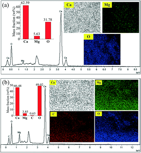 | ||
| Fig. 13 SEM-EDX mapping of C90M10 in Fig. 12: (a) marked region in Fig. 12(a); (b) marked region in Fig. 12(c). | ||
The pore volumes and pore size distributions of C90M10 and carbide slag after the different CaL and THS cycles are displayed in Fig. 14. As shown in Fig. 14(a), after the same THS and CaL cycles, the pore volumes of C90M10 are always higher than those of carbide slag. The pore volume of the original C90M10 is 21% higher than that of the original carbide slag. The pore volumes of the two materials both decrease with the number of THS cycles. It suggests that the small pore volume of the CaO-based material is not beneficial for the hydration reaction during the THS cycles. The two materials after 10 CaL and 30 THS cycles exhibit smaller pore volumes than those after 30 THS cycles, respectively. However, by introducing 1 CaL cycle, the pore volume of C90M10 after 10 CaL and 30 cycles increases by 40% due to the decomposition of the CaCO3 production layer, which contributes to the hydration reaction of C90M10. After 30 THS cycles, the volumes of pores in the range of 18–100 nm in diameter for the two materials both decrease, while those in the range of 2–18 nm in diameter increase, as illustrated in Fig. 14(b). Considering the change in the heat storage capacities of the two materials during the THS cycles, it is concluded that the pores in the range of 18–100 nm in diameter are more crucial for the hydration of CaO. It should be noted that these pores in 18–100 nm in diameter are also very important for CO2 absorption by CaO.54 Thus, the volume of pores in 18–100 nm in diameter show a marked decline due to CO2 absorption by CaO from air and severe aggregation of CaO grains during multiple THS cycles. After 10 CaL and 30 THS cycles, the volume of pores in the range of 18–100 nm in diameter for C90M10 is higher than that for carbide slag. This is probably the reason why C90M10 exhibits higher heat storage capacity than carbide slag after run 4. After the introduction of 1 CaL cycle, the volume of pores in 18–100 nm in diameter for C90M10 after 10 CaL and 30 THS cycles is enhanced by approximately 70.4%. This suggests that the decomposition of the CaCO3 product layer in C90M10 after 10 CaL and 30 THS cycles leads to a considerable increase in the volume of pores in 18–100 nm in diameter. Therefore, the heat storage capacity of C90M10 after run 5 is significantly higher than that after run 4. Therefore, the heat storage capacity of C90M10 using air as the heat transfer fluid is restored by the introduction of CaL cycles during multiple THS cycles.
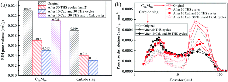 | ||
| Fig. 14 (a) BJH pore volumes and (b) pore size distributions of C90M10 and carbide slag after different CaL and THS cycles. | ||
4. Conclusion
The simultaneous CO2 capture and heat storage performances of the Ca/Mg-based composite prepared from carbide slag and dolomite were studied in a process coupling CaL and CaO/Ca(OH)2 THS using air as the heat transfer fluid of THS. The Ca/Mg-based composite exhibits higher heat storage capacity than carbide slag during 30 THS cycles. When the mass ratio of CaO/MgO is 90![[thin space (1/6-em)]](https://www.rsc.org/images/entities/char_2009.gif) :
:![[thin space (1/6-em)]](https://www.rsc.org/images/entities/char_2009.gif) 10, the composite achieves the highest heat storage capacity and cyclic stability. The X30 and D30 of C90M10 are 0.53 mol mol−1 and 0.90 GJ t−1, respectively, which are 29% and 26% higher than those of carbide slag. MgO derived from dolomite mitigates the aggregation of CaO in the composite in the coupling process. The composite possesses a fluffy and porous structure and exhibits a larger pore volume than carbide slag, resulting in high heat storage capacity in THS cycles. The composite shows higher cyclic CO2 capture capacity than carbide slag. The heat storage capacity of the composite experiencing CaL cycles is also promoted by the presence of MgO. The X30 and D30 of C90M10 experiencing 10 CaL cycles are 85% and 79% higher than those of carbide slag, respectively. The adverse effect of CO2 in air as the heat transfer fluid is overcome by the introduction of CaL cycles in the THS process, and the heat storage capacity of the composite is restored. By introducing 1 CaL cycle after 10th and 20th THS cycles, the X11 and X21 of C90M10 are improved by 31% and 57%, respectively. The cumulative CaCO3 layer formed during the THS process due to the presence of CO2 in air completely converts into CaO in the calcination stage of CaL cycles, so lots of pores in 18–100 nm in diameter are generated, which are important for the hydration of CaO. Moreover, the CO2 capture reactivity of the Ca/Mg-based composite is recovered by the introduction of THS cycles in the CaL process. Therefore, the composite fabricated from industrial waste and dolomite with simultaneous efficient CO2 capture and heat storage capacities seems promising in the process coupling CaL and THS.
10, the composite achieves the highest heat storage capacity and cyclic stability. The X30 and D30 of C90M10 are 0.53 mol mol−1 and 0.90 GJ t−1, respectively, which are 29% and 26% higher than those of carbide slag. MgO derived from dolomite mitigates the aggregation of CaO in the composite in the coupling process. The composite possesses a fluffy and porous structure and exhibits a larger pore volume than carbide slag, resulting in high heat storage capacity in THS cycles. The composite shows higher cyclic CO2 capture capacity than carbide slag. The heat storage capacity of the composite experiencing CaL cycles is also promoted by the presence of MgO. The X30 and D30 of C90M10 experiencing 10 CaL cycles are 85% and 79% higher than those of carbide slag, respectively. The adverse effect of CO2 in air as the heat transfer fluid is overcome by the introduction of CaL cycles in the THS process, and the heat storage capacity of the composite is restored. By introducing 1 CaL cycle after 10th and 20th THS cycles, the X11 and X21 of C90M10 are improved by 31% and 57%, respectively. The cumulative CaCO3 layer formed during the THS process due to the presence of CO2 in air completely converts into CaO in the calcination stage of CaL cycles, so lots of pores in 18–100 nm in diameter are generated, which are important for the hydration of CaO. Moreover, the CO2 capture reactivity of the Ca/Mg-based composite is recovered by the introduction of THS cycles in the CaL process. Therefore, the composite fabricated from industrial waste and dolomite with simultaneous efficient CO2 capture and heat storage capacities seems promising in the process coupling CaL and THS.
Conflicts of interest
There are no conflicts to declare.Acknowledgements
Financial support from the National Natural Science Foundation of China (51876105), the Fundamental Research Funds of Shandong University (2018JC039), and Major Scientific and Technological Innovation Projects of Key R&D Program of Shandong Province (2019JZZY020118) is gratefully appreciated.References
- W. Yuan, H. Wang, M. Han and Z. Yang, Jiejingmei Jishu, 2019, 25, 35–39 Search PubMed.
- P. Huang, B. Zhao, J. Wang, T. Gong, Y. Wang and D. Wang, Jiejingmei Jishu, 2020, 26(03), 60–67 Search PubMed.
- L. Ma, C. Qin, S. Pi and H. Cui, Chem. Eng. J., 2020, 379, 122385 CrossRef CAS.
- Z. Ma, S. Wu and Y. Li, Jiejingmei Jishu, 2019, 25, 1–8 CrossRef.
- Y. Yang, W. Liu, Y. Hu, J. Sun, X. Tong, Q. Chen and Q. Li, Chem. Eng. J., 2018, 353, 92–99 CrossRef CAS.
- A. Silaban and D. P. Harrison, Chem. Eng. Commun., 1995, 137, 177–190 CrossRef CAS.
- T. Shimizu, T. Hirama, H. Hosoda, K. Kitano, M. Inagaki and K. Tejima, Chem. Eng. Res. Des., 1999, 77, 62–68 CrossRef CAS.
- Z. Li, Chem. Eng. Sci., 2020, 227, 115902 CrossRef CAS.
- C. C. Dean, J. Blamey, N. H. Florin, M. J. Al-Jeboori and P. S. Fennell, Chem. Eng. Res. Des., 2011, 89, 836–855 CrossRef CAS.
- A. Lasheras, J. Ströhle, A. Galloy and B. Epple, Int. J. Greenhouse Gas Control, 2011, 5, 686–693 CrossRef CAS.
- S. Tian, F. Yan, Z. Zhang and J. Jiang, Sci. Adv., 2019, 5, eaav5077 CrossRef CAS.
- P. Sun, J. R. Grace, C. J. Lim and E. J. Anthony, Chem. Eng. Sci., 2008, 63, 47–56 CrossRef CAS.
- D. He, Z. Ou, C. Qin, T. Deng, J. Yin and G. Pu, Chem. Eng. J., 2020, 379, 122348 CrossRef CAS.
- J. Blamey, E. J. Anthony, J. Wang and P. S. Fennell, Prog. Energy Combust. Sci., 2010, 36, 260–279 CrossRef CAS.
- J. M. Valverde, P. E. Sanchez-Jimenez and L. A. Perez-Maqueda, J. Phys. Chem. C, 2015, 119, 1623–1641 CrossRef CAS.
- J. Chen, L. Duan, T. Shi, R. Bian, Y. Lu, F. Donat and E. J. Anthony, J. Mater. Chem. A, 2019, 7, 21096–21105 RSC.
- V. Manovic and E. J. Anthony, Environ. Sci. Technol., 2007, 41, 1420–1425 CrossRef CAS.
- J. Chen, T. Shi, L. Duan, Z. Sun and E. J. Anthony, Chem. Eng. J., 2020, 393, 124716 CrossRef CAS.
- J. M. Valverde, A. Perejon, S. Medina and L. A. Perez-Maqueda, Phys. Chem. Chem. Phys., 2015, 17, 30162–30176 RSC.
- B. Sarrion, J. M. Valverde, A. Perejon, L. Perez-Maqueda and P. E. Sanchez-Jimenez, Energy Technol., 2016, 4, 1013–1019 CrossRef CAS.
- S. Tian, J. Jiang, F. Yan, K. Li, X. Chen and V. Manovic, Green Chem., 2016, 18, 4022–4031 RSC.
- B. Azimi, M. Tahmasebpoor, P. E. Sanchez-Jimenez, A. Perejon and J. M. Valverde, Chem. Eng. J., 2019, 358, 679–690 CrossRef CAS.
- A. N. Antzara, A. Arregi, E. Heracleous and A. A. Lemonidou, Chem. Eng. J., 2018, 333, 697–711 CrossRef CAS.
- Y. Hu, W. Liu, W. Wang, J. Sun, X. Yang, H. Chen and M. Xu, Chem. Eng. J., 2016, 296, 412–419 CrossRef CAS.
- J. M. Valverde, M. Barea-Lopez, A. Perejon, P. E. Sanchez-Jimenez and L. A. Perez-Maqueda, Energy Fuels, 2017, 31, 4226–4236 CrossRef CAS.
- C. Yu and W. Chen, Powder Technol., 2013, 239, 492–498 CrossRef CAS.
- C. Luo, Y. Zheng, N. Ding, Q. Wu, G. Bian and C. Zheng, Ind. Eng. Chem. Res., 2010, 49(22), 11778–11784 CrossRef CAS.
- X. Liu, J. Shi, L. He, X. Ma and S. Xu, Chin. J. Chem. Eng., 2017, 25, 572–580 CrossRef CAS.
- J. Park and K. B. Yi, Int. J. Hydrogen Energy, 2012, 37, 95–102 CrossRef CAS.
- Y. Hu, W. Liu, Y. Yang, J. Sun, Z. Zhou and M. Xu, Chem. Eng. Technol., 2017, 40, 2322–2328 CrossRef CAS.
- M. A. Naeem, A. Armutlulu, A. Kierzkowska and C. R. Müller, Energy Procedia, 2017, 114, 158–166 CrossRef CAS.
- J. M. Valverde, P. E. Sanchez-Jimenez and L. A. Perez-Maqueda, Appl. Energy, 2015, 138, 202–215 CrossRef CAS.
- Y. A. Criado, M. Alonso and J. C. Abanades, Ind. Eng. Chem. Res., 2014, 53, 12594–12601 CrossRef CAS.
- L. Dai, X. Long, B. Lou and J. Wu, Appl. Therm. Eng., 2018, 133, 261–268 CrossRef CAS.
- M. Schmidt and M. Linder, Appl. Energy, 2017, 203, 594–607 CrossRef CAS.
- M. Linder, C. Roßkopf, M. Schmidt and A. Wörner, Energy Procedia, 2014, 49, 888–897 CrossRef CAS.
- Y. A. Criado, M. Alonso, J. C. Abanades and Z. Anxionnaz-Minvielle, Appl. Therm. Eng., 2014, 73, 1087–1094 CrossRef CAS.
- F. Schaube, I. Utz, A. Wörner and H. Müller-Steinhagen, Chem. Eng. Res. Des., 2013, 91, 865–873 CrossRef CAS.
- M. Schmidt, C. Szczukowski, C. Roßkopf, M. Linder and A. Wörner, Appl. Therm. Eng., 2014, 62, 553–559 CrossRef CAS.
- S. Lin, Y. Wang and Y. Suzuki, Energy Fuels, 2009, 23, 2855–2861 CrossRef CAS.
- Y. Yuan, Y. Li, L. Duan, H. Liu, J. Zhao and Z. Wang, Energy Convers. Manage., 2018, 174, 8–19 CrossRef CAS.
- F. Schaube, A. Kohzer, J. Schütz, A. Wörner and H. Müller-Steinhagen, Chem. Eng. Res. Des., 2013, 91, 856–864 CrossRef CAS.
- S. Funayama, H. Takasu, M. Zamengo, J. Kariya, S. T. Kim and Y. Kato, Energy Storage, 2019, 1, e53 CrossRef CAS.
- C. Roßkopf, M. Haas, A. Faik, M. Linder and A. Wörner, Energy Convers. Manage., 2014, 86, 93–98 CrossRef.
- K. G. Sakellariou, G. Karagiannakis, Y. A. Criado and A. G. Konstandopoulos, Sol. Energy, 2015, 122, 215–230 CrossRef CAS.
- A. C. Mejia, S. Afflerbach, M. Linder and M. Schmidt, Appl. Therm. Eng., 2020, 169, 114961 CrossRef.
- S. Afflerbach, M. Kappes, A. Gipperich, R. Trettin and W. Krumm, Sol. Energy, 2017, 148, 1–11 CrossRef CAS.
- S. E. B. Edwards and V. Materić, Sol. Energy, 2012, 86, 2494–2503 CrossRef CAS.
- J. Yan, C. Y. Zhao and Z. H. Pan, Energy, 2017, 124, 114–123 CrossRef CAS.
- C. Sun, X. Yan, Y. Li, J. Zhao, Z. Wang and T. Wang, Greenhouse Gases: Sci. Technol., 2020, 10(5), 1027–1038 CrossRef CAS.
- X. Yan, Y. Li, X. Ma, J. Zhao, Z. Wang and H. Liu, New J. Chem., 2019, 43, 5116–5125 RSC.
- C. Ortiz, R. Chacartegui, J. M. Valverde, A. Alovisio and J. A. Becerra, Energy Convers. Manage., 2017, 149, 815–829 CrossRef CAS.
- J. Yin, C. Zhang, C. Qin, W. Liu, H. An, G. Chen and B. Feng, Chem. Eng. J., 2012, 198-199, 38–44 CrossRef CAS.
- H. Chen, C. Zhao, Y. Li and X. Chen, Energy Fuels, 2010, 24, 5751–5756 CrossRef CAS.
| This journal is © The Royal Society of Chemistry 2021 |


